2009 NISSAN LATIO mirror
[x] Cancel search: mirrorPage 2985 of 4331
![NISSAN LATIO 2009 Service Repair Manual EM-38< ON-VEHICLE REPAIR >
[HR16DE]
FUEL INJECTOR AND FUEL TUBE
c. Align center to insert quick connector straightly into fuel tube. • Insert quick connector to fuel tube until the top spoo NISSAN LATIO 2009 Service Repair Manual EM-38< ON-VEHICLE REPAIR >
[HR16DE]
FUEL INJECTOR AND FUEL TUBE
c. Align center to insert quick connector straightly into fuel tube. • Insert quick connector to fuel tube until the top spoo](/manual-img/5/57359/w960_57359-2984.png)
EM-38< ON-VEHICLE REPAIR >
[HR16DE]
FUEL INJECTOR AND FUEL TUBE
c. Align center to insert quick connector straightly into fuel tube. • Insert quick connector to fuel tube until the top spool on fueltube is inserted completely and the 2nd level spool is posi-
tioned slightly below quick connector bottom end.
CAUTION:
• Hold “A” position shown when inserting fuel tube into
quick connector.
• Carefully align center to avoid inclined insertion to pre-
vent damage to O-ring inside quick connector.
• Insert until you hear a “click” sound and actually feel
the engagement.
• To avoid misidentification of engagement with a similar sound, be sure to pe rform the next step.
d. Before clamping fuel feed hose with hose clamp, pull quick connector hard by hand holding “A” position.
Make sure it is completely engaged (connected) so that it does not come out from fuel tube.
e. Install quick connector cap (1) to quick connector connection. • Install quick connector cap with the side arrow facing quick
connector side (fuel feed hose side).
CAUTION:
• Make sure that the quick connector and fuel tube are
securely engaged with the quick connector cap mount-
ing groove.
• Quick connector may not be connected correctly if quick connector cap cannot be installed easily. Remove
the quick connector cap, and then check the connection
of quick connector again.
f. Install fuel feed hose to hose clamp.
7. Installation of the remaining components is in the reverse order of removal.
Inspection INFOID:0000000004784288
INSPECTION AFTER INSTALLATION
Check on Fuel Leakage
1. Turn ignition switch “ON” (with the engine stopped). With fuel pressure applied to fuel piping, make sure
there are no fuel leaks at connection points.
NOTE:
Use mirrors for checking at points out of clear sight.
2. Start the engine. With engine speed increased, make su re again that there are no fuel leaks at connection
points.
CAUTION:
Never touch the engine immediately after it is stopped, as the engine becomes extremely hot. KBIA0272E
PBIC3664E
Page 3106 of 4331
EM
NP
O
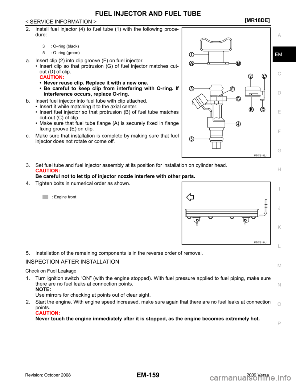
2. Install fuel injector (4) to fuel tube (1) with the following proce-
dure:
a. Insert clip (2) into clip groove (F) on fuel injector. • Insert clip so that protrusion (G) of fuel injector matches cut-
out (D) of clip.
CAUTION:
• Never reuse clip. Replace it with a new one.
• Be careful to keep clip from interfering with O-ring. If
interference occurs, replace O-ring.
b. Insert fuel injector into fuel tube with clip attached. • Insert it while matching it to the axial center.
• Insert fuel injector so that protrusion (B) of fuel tube matches
cut-out (C) of clip.
• Make sure that fuel tube flange (A) is securely fixed in flange
fixing groove (E) on clip.
c. Make sure that installation is complete by making sure that fuel injector does not rotate or come off.
3. Set fuel tube and fuel injector assembly at its position for installation on cylinder head. CAUTION:
Be careful not to let tip of injector nozzle interfere with other parts.
4. Tighten bolts in numerical order as shown.
5. Installation of the remaining components is in the reverse order of removal.
INSPECTION AFTER INSTALLATION
Check on Fuel Leakage 1. Turn ignition switch “ON” (with the engine stopped). With fuel pressure applied to fuel piping, make sure there are no fuel leaks at connection points.
NOTE:
Use mirrors for checking at points out of clear sight.
2. Start the engine. With engine speed increased, make su re again that there are no fuel leaks at connection
points.
CAUTION:
Never touch the engine immediately after it is stopped, as the engine becomes extremely hot.
3 : O–ring (black)
5 : O–ring (green)
Page 3304 of 4331
GW
N
O P
CONTENTS
GLASSES, WINDOW SYSTEM & MIRRORS
SERVICE INFORMATION .. ..........................3
PRECAUTIONS .............................................. .....3
Precaution for Supplemental Restraint System
(SRS) "AIR BAG" and "SEAT BELT PRE-TEN-
SIONER" ............................................................. ......
3
Precaution Necessary fo r Steering Wheel Rota-
tion After Battery Disconnect ............................... ......
3
Precaution for Procedure without Cowl Top Cover ......4
Handling for Adhesive and Primer ...................... ......4
PREPARATION .............................................. .....5
Commercial Service Tool .................................... ......5
SQUEAK AND RATTLE TROUBLE DIAG-
NOSES ........................ ........................................6
Work Flow ........................................................... ......6
Generic Squeak and Rattle Troubleshooting ...... ......8
Diagnostic Worksheet ......................................... ....10
WINDSHIELD GLASS .................................... ....12
Removal and Installation .........................................12
OPERA WINDOW GLASS ............................. ....14
Removal and Installation .........................................14
REAR WINDOW GLASS AND MOLDING ..... ....16
Removal and Installation .........................................16
POWER WINDOW SYST EM ..............................19
Component Parts and Harness Connector Loca-
tion ...................................................................... ....
19
System Description ............................................. ....19
CAN Communication System Description ........... ....23
Schematic ........................................................... ....24
Wiring Diagram - WINDOW- ............................... ....25
Main Power Window and Door Lock/Unlock
Switch Harness Connector Terminal Layout ....... ....
29
Terminal and Reference Value for Main Power
Window and Door Lock/Unlock Switch ............... ....
29
Terminal and Reference Value for BCM ............. ....30
Work Flow ........................................................... ....30 CONSULT-III Function (B
CM) .................................30
Power Window Auto Operat ion Initialization ............31
Trouble Diagnosis Symptom Chart ...................... ....31
BCM Power Supply and Ground Circuit Inspection ....32
Main Power Window and Door Lock/Unlock
Switch Power Supply and Ground Circuit Inspec-
tion ....................................................................... ....
32
Front Power Window Motor LH Circuit Inspection ....33
Front Power Window RH Circuit Inspection (Pow-
er Window and Door Lock/Unlock Switch RH Op-
eration) ................................................................ ....
34
Front Power Window Motor RH Circuit Inspection ....34
Encoder Circuit Inspection ................................... ....36
Door Switch Check .............................................. ....38
Rear Power Window LH Circuit Inspection (Rear
Power Window Switch LH Operation) ................. ....
39
Rear Power Window RH Circu it Inspection (Rear
Power Window Switch RH Operation) ................. ....
40
Rear Power Window Motor LH Circuit Inspection ....40
Rear Power Window Motor RH Circuit Inspection ....42
FRONT DOOR GLASS AND REGULATOR ..... 44
Removal and Installation ..................................... ....44
Disassembly and Assembly ................................. ....46
Inspection after Installati on ......................................46
REAR DOOR GLASS AND REGULATOR ....... 48
Removal and Installation ..................................... ....48
Disassembly and Assembly ................................. ....50
Inspection after Installati on ......................................50
REAR WINDOW DEFOGGER .......................... 51
Component Parts and Harness Connector Loca-
tion ....................................................................... ....
51
System Description .............................................. ....51
CAN Communication System Description ........... ....52
Wiring Diagram - DEF - ....................................... ....53
Terminal and Reference Value for BCM ..................55
Terminal and Reference Va lue for IPDM E/R ..........55
Work Flow ............................................................ ....55
Page 3354 of 4331
GW
N
O P
REAR WINDOW DEFOGGER
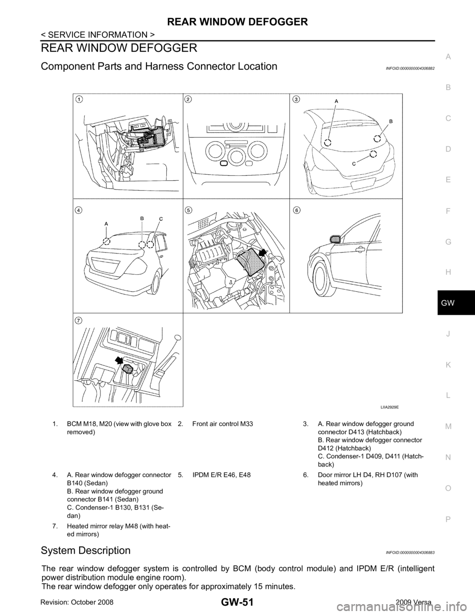
Component Parts and Har ness Connector Location INFOID:0000000004306882
System Description INFOID:0000000004306883
The rear window defogger system is controlled by BCM (body control module) and IPDM E/R (intelligent
power distribution module engine room).
The rear window defogger only operates for approximately 15 minutes. 1. BCM M18, M20 (view with glove box
removed) 2. Front air control M33 3. A. Rear window defogger ground
connector D413 (Hatchback)
B. Rear window defogger connector
D412 (Hatchback)
C. Condenser-1 D4 09, D411 (Hatch-
back)
4. A. Rear window defogger connector B140 (Sedan)
B. Rear window defogger ground
connector B141 (Sedan)
C. Condenser-1 B130, B131 (Se-
dan) 5. IPDM E/R E46, E48 6. Door mirror LH D4, RH D107 (with
heated mirrors)
7. Heated mirror relay M48 (with heat- ed mirrors)
Page 3359 of 4331
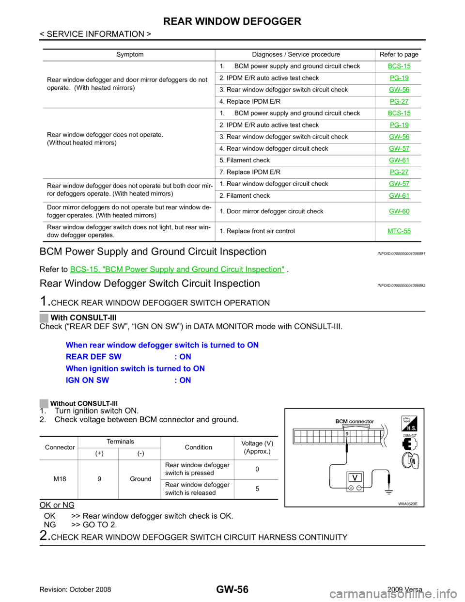
BCM Power Supply and Ground Circuit Inspection " .
Rear Window Defogger Swit ch Circuit Inspection INFOID:0000000004306892OK >> Rear window defogger switch check is OK.
NG >> GO TO 2. 2. IPDM E/R auto active test check
PG-19 3. Rear window defogger switch circuit check
GW-56 4. Replace IPDM E/R
PG-27Rear window defogger does not operate.
(Without heated mirrors) 1. BCM power supply and ground circuit check
BCS-15 2. IPDM E/R auto active test check
PG-19 3. Rear window defogger switch circuit check
GW-56 4. Rear window defogger circuit check
GW-57 5. Filament check
GW-61 7. Replace IPDM E/R
PG-27Rear window defogger does not operate but both door mir-
ror defoggers operate. (With heated mirrors) 1. Rear window defogger circuit check
GW-57 2. Filament check
GW-61Door mirror defoggers do not operate but rear window de-
fogger operates. (With heated mirrors) 1. Door mirror defogger circuit check
GW-60Rear window defogger switch does not light, but rear win-
dow defogger operates. 1. Replace front air control
MTC-55
Page 3363 of 4331
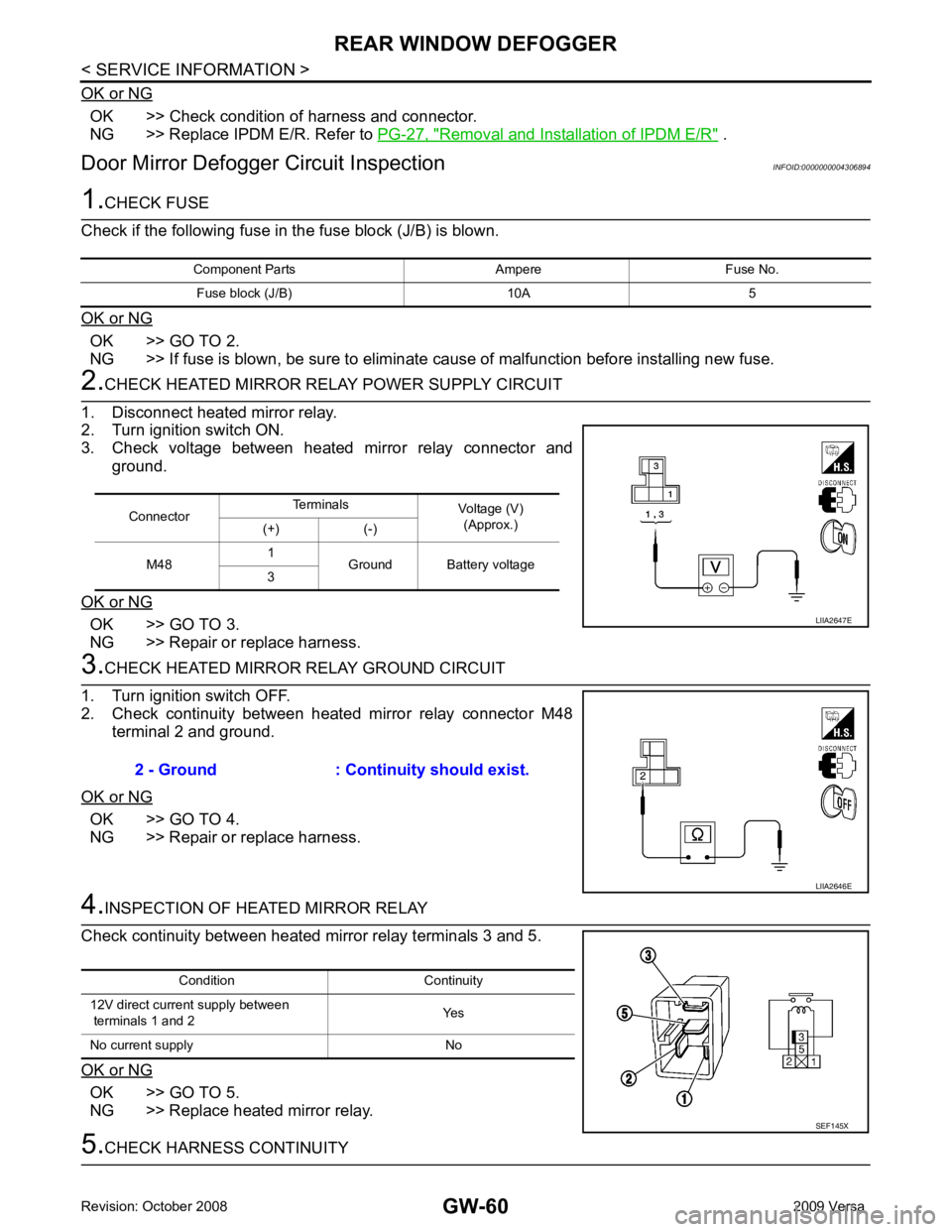
OK >> Check condition of harness and connector.
NG >> Replace IPDM E/R. Refer to PG-27, " Removal and Installation of IPDM E/R " .
Door Mirror Defogger Circuit Inspection INFOID:0000000004306894OK >> GO TO 2.
NG >> If fuse is blown, be sure to eliminate cause of malfunction before installing new fuse. OK >> GO TO 3.
NG >> Repair or replace harness. OK >> GO TO 4.
NG >> Repair or replace harness. OK >> GO TO 5.
NG >> Replace heated mirror relay. Connector
Terminals
Voltage (V)
(Approx.)
(+) (-)
M48 1
Ground Battery voltage
3
Page 3364 of 4331
GW
N
O P
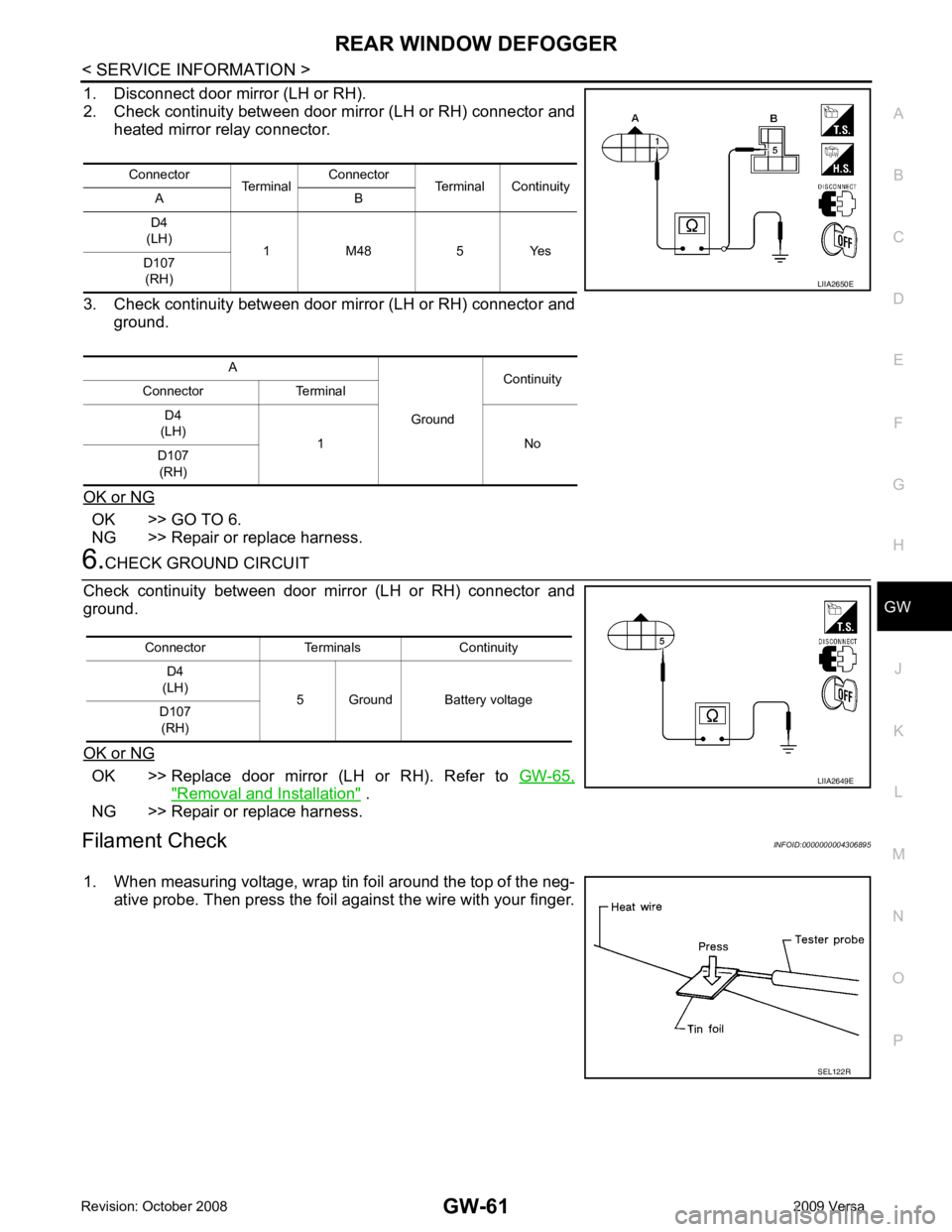
1. Disconnect door mirror (LH or RH).
2. Check continuity between door mirror (LH or RH) connector and heated mirror relay connector.
3. Check continuity between door mirror (LH or RH) connector and ground.
OK or NG OK >> GO TO 6.
NG >> Repair or replace harness. OK >> Replace door mirror (LH or RH). Refer to
GW-65," Removal and Installation " .
NG >> Repair or replace harness.
Filament Check INFOID:0000000004306895
1. When measuring voltage, wrap tin foil around the top of the neg- ative probe. Then press the foil against the wire with your finger.Connector
TerminalConnector
Terminal Continuity
A B
D4
(LH) 1 M48 5 Yes
D107
(RH)
A GroundContinuity
Connector Terminal
D4
(LH) 1 No
D107
(RH) SEL122R
Page 3368 of 4331
GW
N
O P
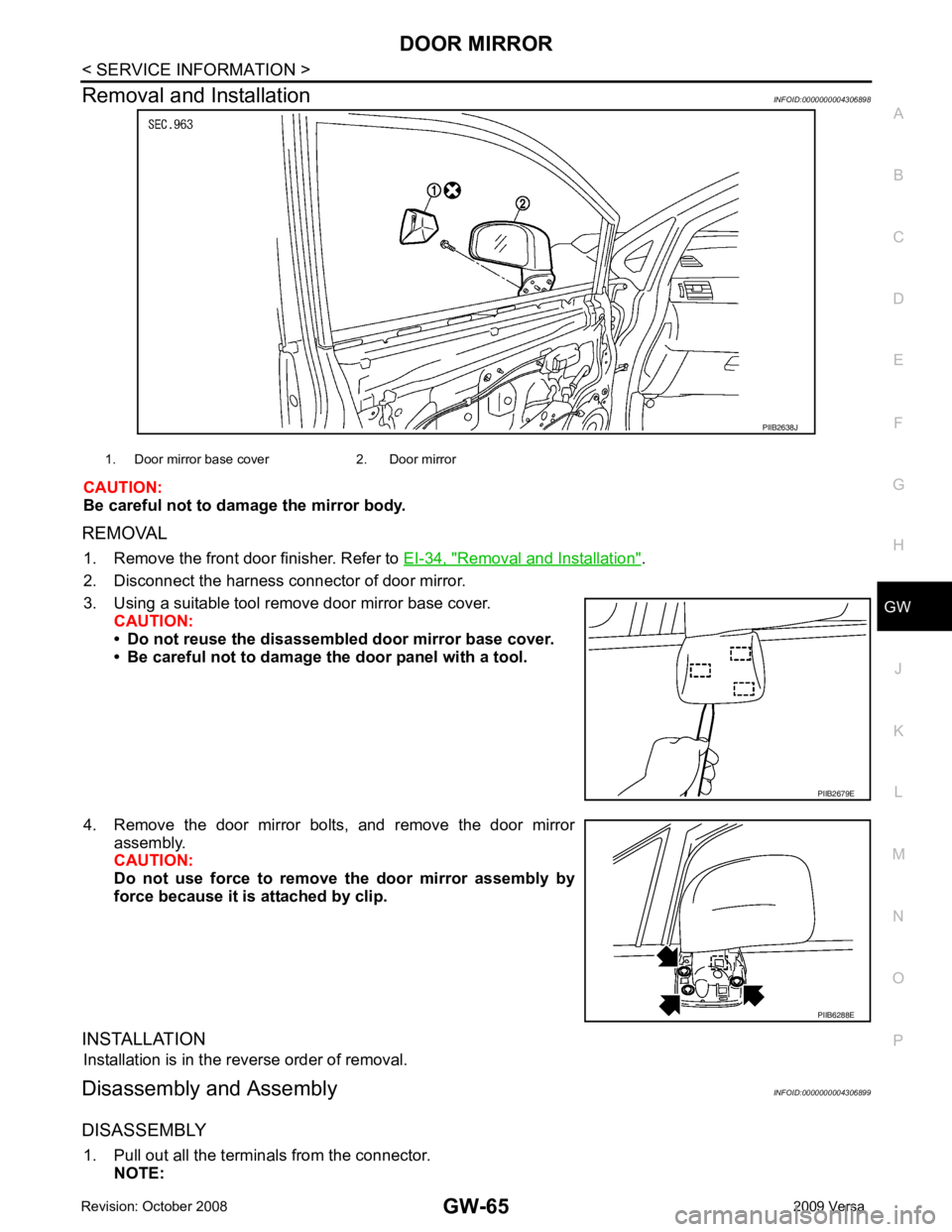
Removal and Installation
INFOID:0000000004306898
CAUTION:
Be careful not to damage the mirror body.
REMOVAL 1. Remove the front door finisher. Refer to EI-34, " Removal and Installation " .
2. Disconnect the harness connector of door mirror.
3. Using a suitable tool remove door mirror base cover. CAUTION:
• Do not reuse the disassembl ed door mirror base cover.
• Be careful not to damage the door panel with a tool.
4. Remove the door mirror bolts, and remove the door mirror assembly.
CAUTION:
Do not use force to remove the door mirror assembly by
force because it is attached by clip.
INSTALLATION Installation is in the reverse order of removal.
Disassembly and Assembly INFOID:0000000004306899
DISASSEMBLY 1. Pull out all the terminals from the connector. NOTE: PIIB6288E