2009 NISSAN LATIO relay
[x] Cancel search: relayPage 858 of 4331
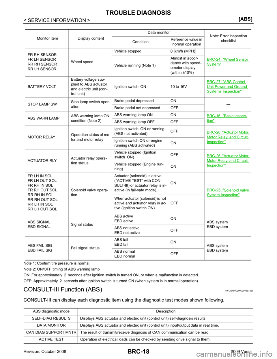
Wheel Sensor
System "
Vehicle running (Note 1)
Almost in accor-
dance with speed-
ometer display
(within ±10%)
BATTERY VOLT Battery voltage sup-
plied to ABS actuator
and electric unit (con-
trol unit) Ignition switch ON 10 to 16V
BRC-27, " ABS Control
Unit Power and Ground
Systems Inspection "
STOP LAMP SW
Stop lamp switch oper-
ation Brake pedal depressed ON
—
Brake pedal not depressed OFF
ABS WARN LAMP ABS warning lamp ON
condition (Note 2) ABS warning lamp ON ON
BRC-16, " Basic Inspec-
tion "
ABS warning lamp OFF OFF
MOTOR RELAY Operation status of mo-
tor and motor relay Ignition switch ON or running
(ABS not activated) OFF
BRC-26, " Actuator Motor,
Motor Relay, and Circuit
Inspection "Ignition switch ON or engine
running (ABS activated) ON
ACTUATOR RLY Actuator relay opera-
tion status Vehicle stopped (Ignition
switch ON) OFF
BRC-26, " Actuator Motor,
Motor Relay, and Circuit
Inspection "Vehicle stopped (Engine run-
ning) ON
FR LH IN SOL
FR LH OUT SOL
FR RH IN SOL
FR RH OUT SOL
RR RH IN SOL
RR RH OUT SOL
RR LH IN SOL
RR LH OUT SOL Solenoid valve opera-
tion Actuator (solenoid) is active
(“ACTIVE TEST” with CON-
SULT-III) or actuator relay is in-
active (in fail-safe mode). ON
BRC-25, " Solenoid Valve
System Inspection "
When actuator (solenoid) is not
active and actuator relay is ac-
tive (ignition switch ON). OFF
ABS SIGNAL
EBD SIGNAL Signal statusABS active
EBD active ON
ABS system
EBD system
ABS not active
EBD not active OFF
ABS FAIL SIG
EBD FAIL SIG Fail signal statusABS fail
EBD fail ON
ABS system
EBD system
ABS normal
EBD normal OFFABS diagnostic mo
de Description
SELF-DIAG RESULTS Displays ABS actuator and electric unit (control unit) self-diagnosis results.
DATA MONITOR Displays ABS actuator and electric unit (control unit) input/output data in real time.
CAN DIAG SUPPORT MNTR The result of transmit/receive diagnosis of CAN communication can be read. ACTIVE TEST Operation of electrical loads can be checked by sending drive signal to them.
Page 860 of 4331
![NISSAN LATIO 2009 Service Repair Manual Wheel Sensor
System " (Note 1)
RR LH SENSOR-1
[C1102] Circuit of rear LH wheel sensor is open.
FR RH SENSOR-1
[C1103] Circuit of front RH wheel sensor is open.
FR LH SENSOR-1
[C1104] Circuit of fron NISSAN LATIO 2009 Service Repair Manual Wheel Sensor
System " (Note 1)
RR LH SENSOR-1
[C1102] Circuit of rear LH wheel sensor is open.
FR RH SENSOR-1
[C1103] Circuit of front RH wheel sensor is open.
FR LH SENSOR-1
[C1104] Circuit of fron](/manual-img/5/57359/w960_57359-859.png)
Wheel Sensor
System " (Note 1)
RR LH SENSOR-1
[C1102] Circuit of rear LH wheel sensor is open.
FR RH SENSOR-1
[C1103] Circuit of front RH wheel sensor is open.
FR LH SENSOR-1
[C1104] Circuit of front LH wheel sensor is open.
RR RH SENSOR-2
[C1105] When the circuit in the rear RH wheel sensor is short-circuited or
when the sensor power voltage is outside the standard. When the
distance between the wheel sensor and sensor rotor is too large
and the sensor pulse cannot be recognized by the control unit.
RR LH SENSOR-2
[C1106] When the circuit in the rear LH wheel sensor is short-circuited or
when the sensor power voltage is outside the standard. When the
distance between the wheel sensor and sensor rotor is too large
and the sensor pulse cannot be recognized by the control unit.
FR RH SENSOR-2
[C1107] When the circuit in the front RH wheel sensor is short-circuited or
when the sensor power voltage is outside the standard. When the
distance between the wheel sensor and sensor rotor is too large
and the sensor pulse cannot be recognized by the control unit.
FR LH SENSOR-2
[C1108] When the circuit in the front LH wheel sensor is short-circuited or
when the sensor power voltage is outside the standard. When the
distance between the wheel sensor and sensor rotor is too large
and the sensor pulse cannot be recognized by the control unit.
ABS SENSOR
[ABNORMAL SIGNAL]
[C1115] Wheel sensor input is abnormal.
BATTERY VOLTAGE
[ABNORMAL]
[C1109] ABS actuator and electric unit (control unit) power voltage is too
low. BRC-27, " ABS Control
Unit Power and Ground
Systems Inspection "
CONTROLLER FAILURE
[C1110] Internal malfunction of ABS actuator
and electric unit (control unit)BRC-25, " ABS Control
Unit Inspection "
PUMP MOTOR
[C1111] During actuator motor operation with ON, when actuator motor
turns OFF or when control line for actuator motor relay is open. BRC-26, " Actuator Mo-
tor, Motor Relay, and Cir-
cuit Inspection "During actuator motor operation with OFF, when actuator motor
turns ON or when control line for relay is shorted to ground.
FR LH IN ABS SOL
[C1120] Circuit of front LH IN ABS solenoid
is open or shorted, or control
line is open or shorted to power supply or ground.
BRC-25, " Solenoid Valve
System Inspection "FR LH OUT ABS SOL
[C1121] Circuit of front LH OUT ABS solenoid is open or shorted, or control
line is open or shorted to power supply or ground.
FR RH IN ABS SOL
[C1122] Circuit of front RH IN ABS solenoid is open or shorted, or control
line is open or shorted to power supply or ground.
FR RH OUT ABS SOL
[C1123] Circuit of front RH OUT ABS solenoid is open or shorted, or con-
trol line is open or shorted to power supply or ground.
RR LH IN ABS SOL
[C1124] Circuit of rear LH IN ABS solenoid
is open or shorted, or control
line is open or shorted to power supply or ground.
RR LH OUT ABS SOL
[C1125] Circuit of rear LH OUT ABS solenoid
is open or shorted, or control
line is open or shorted to power supply or ground.
RR RH IN ABS SOL
[C1126] Circuit of rear RH IN ABS solenoid
is open or shorted, or control
line is open or shorted to power supply or ground.
RR RH OUT ABS SOL
[C1127] Circuit of rear RH OUT ABS solenoid is open or shorted, or control
line is open or shorted to power supply or ground.
Page 861 of 4331
BRC
N
O P
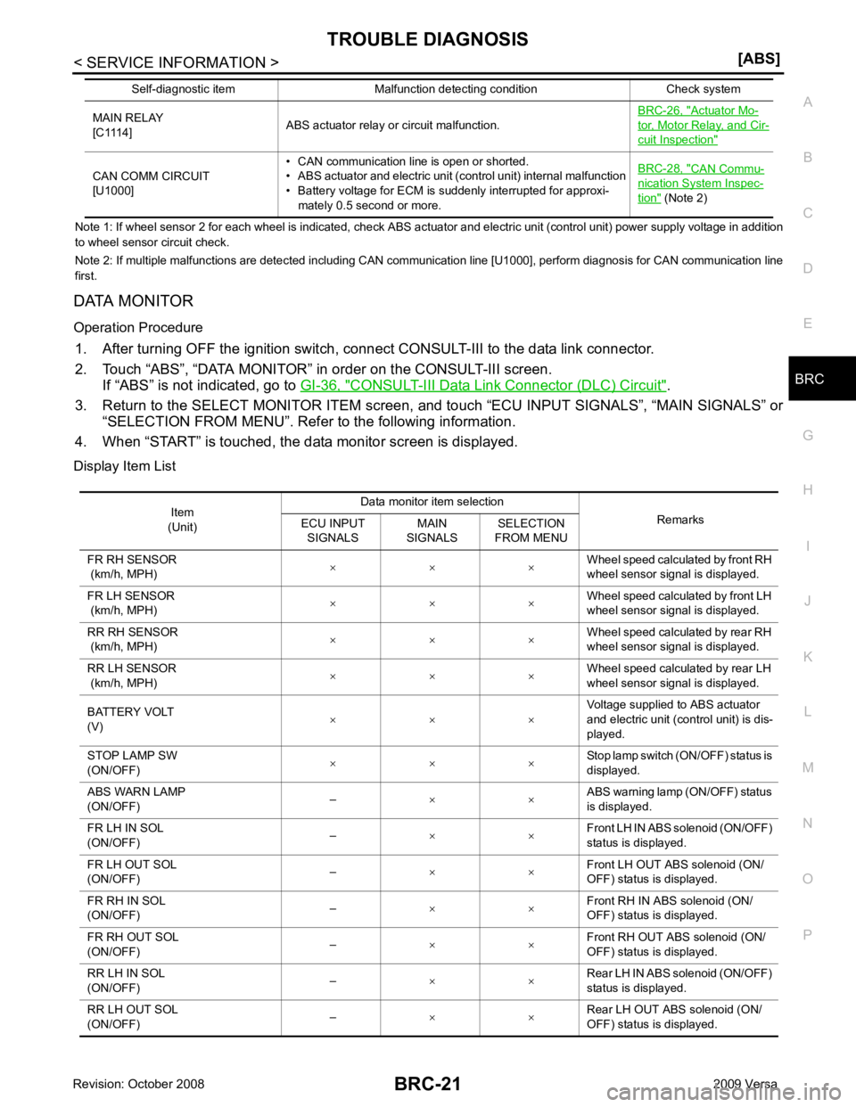
Note 1: If wheel sens
or 2 for each wheel is indicated, check ABS actuator and electric unit (control unit) power supply voltage in addition
to wheel sensor circuit check.
Note 2: If multiple malfunctions are detected including CAN communication line [U1000], perform diagnosis for CAN communication line
first.
DATA MONITOR
Operation Procedure 1. After turning OFF the ignition switch, c onnect CONSULT-III to the data link connector.
2. Touch “ABS”, “DATA MONITOR” in order on the CONSULT-III screen. If “ABS” is not indicated, go to GI-36, " CONSULT-III Data Link Connector (DLC) Circuit " .
3. Return to the SELECT MONITOR ITEM screen, and touch “ECU INPUT SIGNALS”, “MAIN SIGNALS” or
“SELECTION FROM MENU”. Refer to the following information.
4. When “START” is touched, the data monitor screen is displayed.
Display Item List MAIN RELAY
[C1114] ABS actuator relay or circuit malfunction. BRC-26, " Actuator Mo-
tor, Motor Relay, and Cir-
cuit Inspection "
CAN COMM CIRCUIT
[U1000] • CAN communication line is open or shorted.
• ABS actuator and electric unit (control unit) internal malfunction
• Battery voltage for ECM is suddenly interrupted for approxi-
mately 0.5 second or more. BRC-28, " CAN Commu-
nication System Inspec-
tion " (Note 2)
Self-diagnostic item Malfunction detecting condition Check system Item
(Unit) Data monitor item selection
Remarks
ECU INPUT
SIGNALS MAIN
SIGNALS SELECTION
FROM MENU
FR RH SENSOR
(km/h, MPH) × × × Wheel speed calculated by front RH
wheel sensor signal is displayed.
FR LH SENSOR
(km/h, MPH) × × ×
Wheel speed calculated by front LH
wheel sensor signal is displayed.
RR RH SENSOR
(km/h, MPH) × × × Wheel speed calculated by rear RH
wheel sensor signal is displayed.
RR LH SENSOR
(km/h, MPH) × × × Wheel speed calculated by rear LH
wheel sensor signal is displayed.
BATTERY VOLT
(V) × × × Voltage supplied to ABS actuator
and electric unit (control unit) is dis-
played.
STOP LAMP SW
(ON/OFF) × × × Stop lamp switch (ON/OFF) status is
displayed.
ABS WARN LAMP
(ON/OFF) –
× × ABS warning lamp (ON/OFF) status
is displayed.
FR LH IN SOL
(ON/OFF) –
× × Front LH IN ABS solenoid (ON/OFF)
status is displayed.
FR LH OUT SOL
(ON/OFF) –
× × Front LH OUT ABS solenoid (ON/
OFF) status is displayed.
FR RH IN SOL
(ON/OFF) –
× × Front RH IN ABS solenoid (ON/
OFF) status is displayed.
FR RH OUT SOL
(ON/OFF) –
× × Front RH OUT ABS solenoid (ON/
OFF) status is displayed.
RR LH IN SOL
(ON/OFF) –
× × Rear LH IN ABS solenoid (ON/OFF)
status is displayed.
RR LH OUT SOL
(ON/OFF) –
× × Rear LH OUT ABS solenoid (ON/
OFF) status is displayed.
Page 862 of 4331
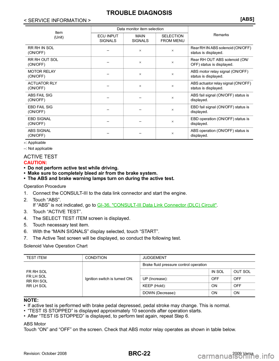
CONSULT-III Data Link Connector (DLC) Circuit " .
3. Touch “ACTIVE TEST”.
4. The SELECT TEST ITEM screen is displayed.
5. Touch necessary test item.
6. With the “MAIN SIGNALS” display selected, touch “START”.
7. The Active Test screen will be displayed, so conduct the following test.
Solenoid Valve Operation Chart
NOTE:
• If active test is performed with brake pedal depr essed, pedal stroke may change. This is normal.
• “TEST IS STOPPED” is displayed approximately 10 seconds after operation starts.
• After “TEST IS STOPPED” is displayed, to perform test again, repeat Step 6.
ABS Motor
Touch “ON” and “OFF” on the screen. Check that ABS motor relay operates as shown in table below.
RR RH IN SOL
(ON/OFF) –
× × Rear RH IN ABS solenoid (ON/OFF)
status is displayed.
RR RH OUT SOL
(ON/OFF) –
× × Rear RH OUT ABS solenoid (ON/
OFF) status is displayed.
MOTOR RELAY
(ON/OFF) –
× × ABS motor relay signal (ON/OFF)
status is displayed.
ACTUATOR RLY
(ON/OFF) –
× × ABS actuator relay signal (ON/OFF)
status is displayed.
ABS FAIL SIG
(ON/OFF) – –
×ABS fail signal (ON/OFF) status is
displayed.
EBD FAIL SIG
(ON/OFF) – –
×EBD fail signal (ON/OFF) status is
displayed.
EBD SIGNAL
(ON/OFF) – –
×EBD operation (ON/OFF) status is
displayed.
ABS SIGNAL
(ON/OFF) – –
×ABS operation (ON/OFF) status is
displayed.
Item
(Unit) Data monitor item selection
Remarks
ECU INPUT
SIGNALS MAIN
SIGNALS SELECTION
FROM MENU TEST ITEM CONDITION JUDGEMENT
FR RH SOL
FR LH SOL
RR RH SOL
RR LH SOL Ignition switch is turned ON.Brake fluid pressure control operation
IN SOL OUT SOL
UP (Increase): OFF OFF
KEEP (Hold): ON OFF
DOWN (Decrease): ON ON
Page 863 of 4331

BRC
N
O P
NOTE:
• If active test is performed with brake pedal depressed, pedal stroke may change. This is normal.
• “TEST IS STOPPED” is displayed approx imately 10 seconds after operation starts.
Operation ON OFF
ABS actuator relay ON ON
ABS motor relay ON OFF
Page 953 of 4331
CVT
N
O P
SERVICE INFORMATION
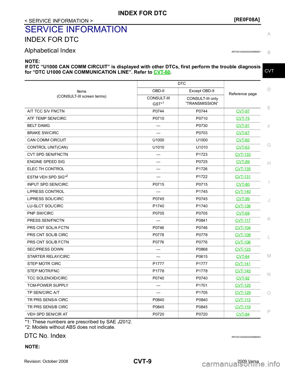
INDEX FOR DTC
Alphabetical Index INFOID:0000000004666851
NOTE:
If DTC “U1000 CAN COMM CIRCUIT” is displayed with other DTCs, first perform the trouble diagnosis
for “DTC U1000 CAN COMMUNICATION LINE”. Refer to CVT-60 .
*1: These numbers are prescribed by SAE J2012.
*2: Models without ABS does not indicate.
DTC No. Index INFOID:0000000004666852
NOTE: Items
(CONSULT-III screen terms) DTC
Reference page
OBD-II Except OBD-II
CONSULT-III GST* 1 CONSULT-III only
“TRANSMISSION”
A/T TCC S/V FNCTN P0744 P0744 CVT-97ATF TEMP SEN/CIRC P0710 P0710
CVT-75BELT DAMG — P0730
CVT-91BRAKE SW/CIRC — P0703
CVT-67CAN COMM CIRCU
IT U1000 U1000 CVT-60CONTROL UNIT(CAN) U1010 U1010
CVT-63CVT SPD SEN/FNCTN — P1723
CVT-133ENGINE SPEED SIG — P0725
CVT-89ELEC TH CONTROL — P1726
CVT-135ESTM VEH SPD SIG*
2
— P1722CVT-131INPUT SPD SEN/CIRC P0715 P0715
CVT-80L/PRESS CONTROL — P1745
CVT-140L/PRESS SOL/CIRC P0745 P0745
CVT-99LU-SLCT SOL/CIRC P1740 P1740
CVT-136PNP SW/CIRC P0705 P0705
CVT-69PRESS SEN/FNCTN — P0841
CVT-117PRS CNT SOL/A FCTN P0746 P0746
CVT-104PRS CNT SOL/B CIRC P0778 P0778
CVT-108PRS CNT SOL/B FCTN P0776 P0776
CVT-106SEC/PRESS DOWN — P0868
CVT-123STARTER RELAY/CIRC — P0615
CVT-64STEP MOTR CIRC P1777 P1777
CVT-141STEP MOTR/FNC P1778 P1778
CVT-145TCC SOLENOID/CIRC P0740 P0740
CVT-92TCM-POWER SUPPLY — P1701
CVT-125TP SEN/CIRC A/T — P1705
CVT-129TR PRS SENS/A CIRC P0840 P0840
CVT-113TR PRS SENS/B CIRC P0845 P0845
CVT-119VEH SPD SEN/CIR AT P0720 P0720
CVT-84
Page 954 of 4331

.
*1: These numbers are pr escribed by SAE J2012.
*2: Models without ABS does not indicate. DTC
Items
(CONSULT-III screen terms) Reference page
OBD-II Except OBD-II
CONSULT-III GST* 1 CONSULT-III only
“TRANSMISSION”
— P0615 STARTER RELAY/CIRC CVT-64— P0703 BRAKE SW/CIRC
CVT-67P0705 P0705 PNP SW/CIRC
CVT-69P0710 P0710 ATF TEMP SEN/CIRC
CVT-75P0715 P0715 INPUT SPD SEN/CIRC
CVT-80P0720 P0720 VEH SPD SEN/CIR AT
CVT-84— P0725 ENGINE SPEED SIG
CVT-89— P0730 BELT DAMG
CVT-91P0740 P0740 TCC SOLENOID/CIRC
CVT-92P0744 P0744 A/T TCC S/V FNCTN
CVT-97P0745 P0745 L/PRESS SOL/CIRC
CVT-99P0746 P0746 PRS CNT SOL/A FCTN
CVT-104P0776 P0776 PRS CNT SOL/B FCTN
CVT-106P0778 P0778 PRS CNT SOL/B CIRC
CVT-108P0840 P0840 TR PRS SENS/A CIRC
CVT-113— P0841 PRESS SEN/FNCTN
CVT-117P0845 P0845 TR PRS SENS/B CIRC
CVT-119— P0868 SEC/PRESS DOWN
CVT-123— P1701 TCM-POWER SUPPLY
CVT-125— P1705 TP SEN/CIRC A/T
CVT-129— P1722
ESTM VEH SPD SIG*2
CVT-131— P1723 CVT SPD SEN/FNCTN
CVT-133— P1726 ELEC TH CONTROL
CVT-135P1740 P1740 LU-SLCT SOL/CIRC
CVT-136— P1745 L/PRESS CONTROL
CVT-140P1777 P1777 STEP MOTR CIRC
CVT-141P1778 P1778 STEP MOTR/FNC
CVT-145U1000 U1000 CAN COMM CIRCUIT
CVT-60U1010 U1010 CONTROL UNIT(CAN)
CVT-63
Page 998 of 4331
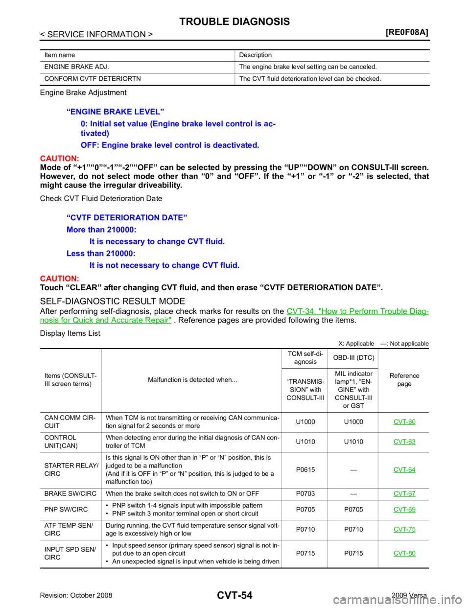
How to Perform Trouble Diag-
nosis for Quick and Accurate Repair " . Reference pages are provided following the items.
Display Items List X: Applicable —: Not applicable
Item name Description
ENGINE BRAKE ADJ. The engine brake level setting can be canceled.
CONFORM CVTF DETERIORTN The CVT fluid deterioration level can be checked. CONTROL
UNIT(CAN) When detecting error during the initial diagnosis of CAN con-
troller of TCM U1010 U1010
CVT-63STARTER RELAY/
CIRC Is this signal is ON other than in “P” or “N” position, this is
judged to be a malfunction
(And if it is OFF in “P” or “N” position, this is judged to be a
malfunction too) P0615 —
CVT-64BRAKE SW/CIRC When the brake switch does
not switch to ON or OFF P0703 — CVT-67PNP SW/CIRC
• PNP switch 1-4 signals input with impossible pattern
• PNP switch 3 monitor terminal open or short circuit P0705 P0705
CVT-69ATF TEMP SEN/
CIRC During running, the CVT fluid temperature sensor signal volt-
age is excessively high or low P0710 P0710
CVT-75INPUT SPD SEN/
CIRC • Input speed sensor (primary speed sensor) signal is not in-
put due to an open circuit
• An unexpected signal is input when vehicle is being driven P0715 P0715
CVT-80