2009 NISSAN LATIO relay
[x] Cancel search: relayPage 3679 of 4331
PARKING, LICENSE PL
ATE AND TAIL LAMPS
LT-73
< SERVICE INFORMATION >
C
D E
F
G H
I
J
L
M A
B LT
N
O P
PARKING, LICENSE PLATE AND TAIL LAMPS
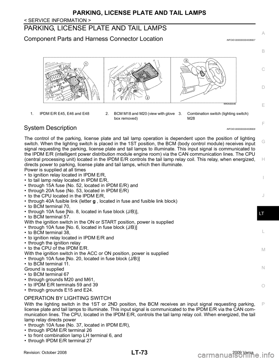
Component Parts and Har ness Connector Location INFOID:0000000004306607
System Description INFOID:0000000004306608
The control of the parking, license plate and tail lamp operation is dependent upon the position of lighting
switch. When the lighting switch is placed in the 1ST position, the BCM (body control module) receives input
signal requesting the parking, license plate and tail lamps to illuminate. This input signal is communicated to
the IPDM E/R (intelligent power distribution module engine room) via the CAN communication lines. The CPU
(central processing unit) located in the IPDM E/R contro ls the tail lamp relay coil. This relay, when energized,
directs power to parking, license plate and tail lamps, which then illuminate.
Power is supplied at all times
• to ignition relay located in IPDM E/R,
• to tail lamp relay located in IPDM E/R,
• through 15A fuse (No. 52, located in IPDM E/R) and
• through 20A fuse (No. 53, located in IPDM E/R)
• to the CPU located in the IPDM E/R,
• through 40A fusible link (letter g , located in fuse and fusible link block)
• to BCM terminal 70,
• through 10A fuse [No. 8, located in fuse block (J/B)],
• to BCM terminal 57.
With the ignition switch in the ON or START position, power is supplied
• through 10A fuse [No. 6, located in fuse block (J/B)]
• to BCM terminal 38,
• to ignition relay located in IPDM E/R and
• through the ignition relay
• to the CPU of the IPDM E/R.
With the ignition switch in the ACC or ON position, power is supplied
• through 10A fuse [No. 20, located in fuse block (J/B)]
• to BCM terminal 11.
Ground is supplied
• to BCM terminal 67
• through grounds M20 and M61,
• to IPDM E/R terminals 59 and 39
• through grounds E15 and E24.
OPERATION BY LIGHTING SWITCH With the lighting switch in the 1ST or 2ND positi on, the BCM receives an input signal requesting parking,
license plate and tail lamps to illuminate. This input si gnal is communicated to the IPDM E/R via the CAN com-
munication lines. The CPU, located in the IPDM E/R, c ontrols the tail lamp relay coil. When energized, the tail
lamp relay directs power
• through 10A fuse (No. 37, located in IPDM E/R),
• through IPDM E/R terminal 26
• to front combination lamp LH terminal 6, and
• through IPDM E/R terminal 27 1. IPDM E/R E45, E46 and E48 2. BCM M18 and M20 (view with glove
box removed)3. Combination switch (lighting switch)
M28 WKIA5554E
Page 3687 of 4331
LT
N
O P
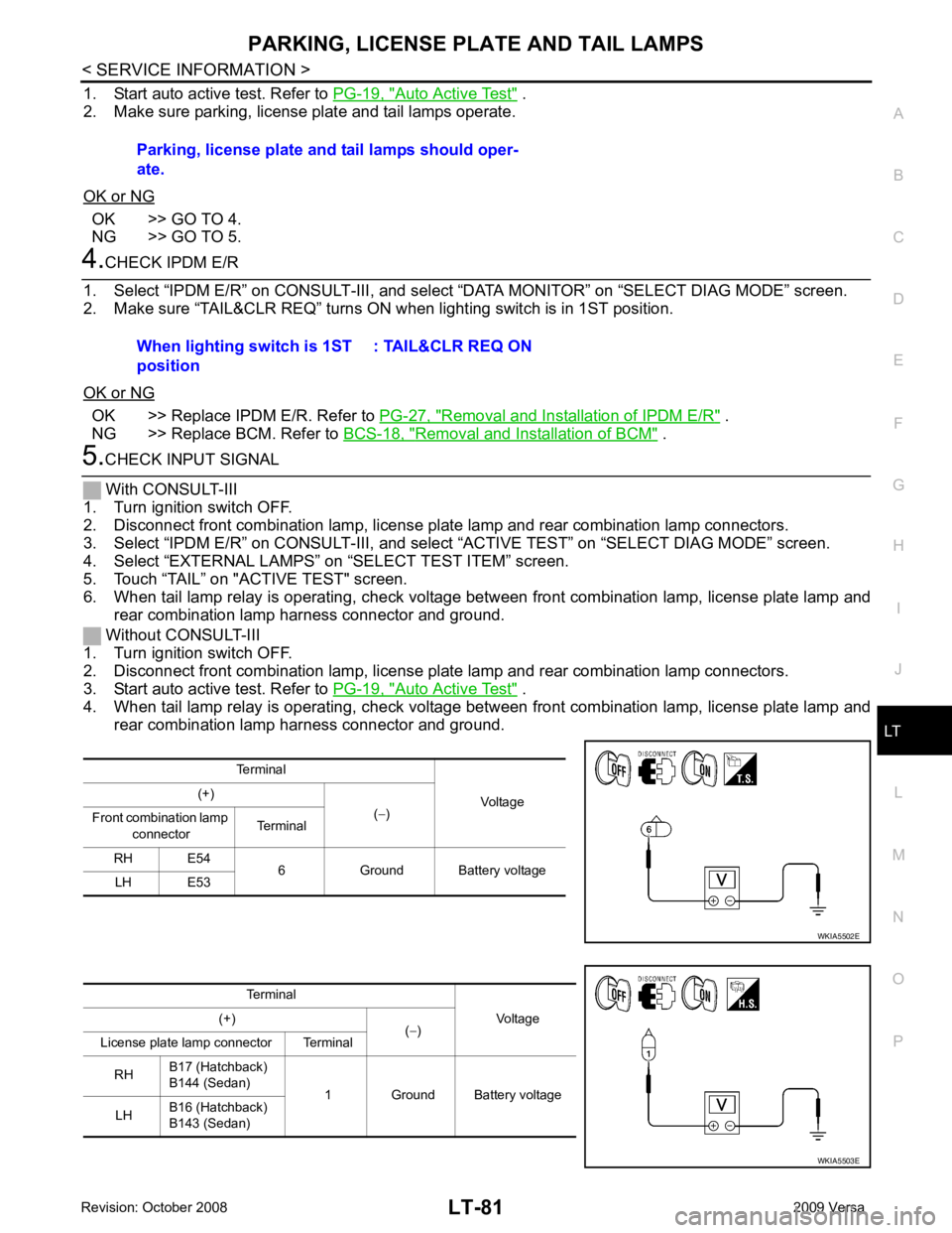
1. Start auto active test. Refer to
PG-19, " Auto Active Test " .
2. Make sure parking, license plate and tail lamps operate.
OK or NG OK >> GO TO 4.
NG >> GO TO 5. OK >> Replace IPDM E/R. Refer to
PG-27, " Removal and Installation of IPDM E/R " .
NG >> Replace BCM. Refer to BCS-18, " Removal and Installation of BCM " .
Auto Active Test " .
4. When tail lamp relay is operating, check voltage bet ween front combination lamp, license plate lamp and
rear combination lamp harness connector and ground. Parking, license plate and tail lamps should oper-
ate.
When lighting switch is 1ST
position : TAIL&CLR REQ ON
Terminal Voltage
(+)
(− )
Front combination lamp
connector Terminal
RH E54 6 Ground Battery voltage
LH E53
Page 3689 of 4331
LT
N
O P
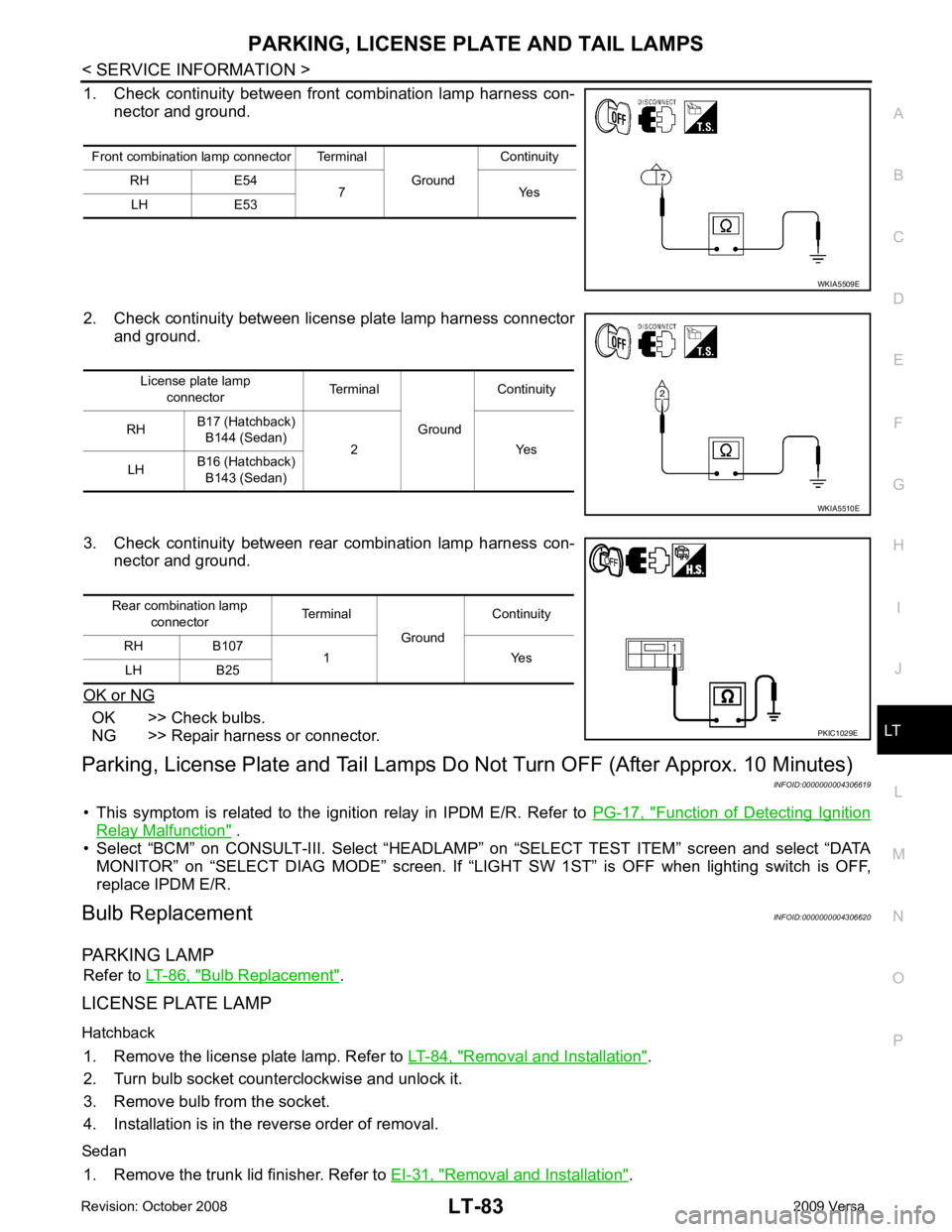
1. Check continuity between front
combination lamp harness con-
nector and ground.
2. Check continuity between license plate lamp harness connector and ground.
3. Check continuity between rear combination lamp harness con- nector and ground.
OK or NG OK >> Check bulbs.
NG >> Repair harness or connector.
Parking, License Plate and Tail Lamps Do Not Turn OFF (After Approx. 10 Minutes)
INFOID:0000000004306619
• This symptom is related to the ignition relay in IPDM E/R. Refer to PG-17, " Function of Detecting Ignition
Relay Malfunction " .
• Select “BCM” on CONSULT-III. Select “HEADLAM P” on “SELECT TEST ITEM” screen and select “DATA
MONITOR” on “SELECT DIAG MODE” sc reen. If “LIGHT SW 1ST” is OFF when lighting switch is OFF,
replace IPDM E/R.
Bulb Replacement INFOID:0000000004306620
PARKING LAMP Refer to LT-86, " Bulb Replacement " .
LICENSE PLATE LAMP
Hatchback 1. Remove the license plate lamp. Refer to LT-84, " Removal and Installation " .
2. Turn bulb socket counterclockwise and unlock it.
3. Remove bulb from the socket.
4. Installation is in the reverse order of removal.
Sedan 1. Remove the trunk lid finisher. Refer to EI-31, " Removal and Installation " .
Front combination lamp connector Terminal
GroundContinuity
RH E54 7 Yes
LH E53
Page 3713 of 4331

LT
N
O P
ILLUMINATION
System Description INFOID:0000000004306640
The control of the illumination lamps operation is dependent upon the position of the lighting switch. When the
lighting switch is placed in the 1ST or 2ND position, the BCM (body control module) receives input signal
requesting the illumination lamps to illuminate. This input signal is communicated to IPDM E/R (intelligent
power distribution module engine room) across CAN communication lines. CPU (central processing unit)
located in the IPDM E/R controls the tail lamp relay coil . This relay, when energized, directs power to the illu-
mination lamps, which then illuminate.
Power is supplied at all times
• to ignition relay, located in IPDM E/R,
• to tail lamp relay, located in IPDM E/R,
• through 15A fuse (No. 52, located in IPDM E/R) and
• through 20A fuse (No. 53, located in IPDM E/R)
• to CPU located in IPDM E/R,
• through 40A fusible link (letter g, located in fuse and fusible link box)
• to BCM terminal 70, and
• through 10A fuse [No. 8, located in fuse block (J/B)]
• to BCM terminal 57.
With the ignition switch in the ON or START position, power is supplied
• to ignition relay, located in IPDM E/R, and
• through 10A fuse [No. 6, located in fuse block (J/B)]
• to BCM terminal 38.
With the ignition switch in the ACC or ON position, power is supplied
• through 10A fuse [No. 20, located in fuse block (J/B)]
• to BCM terminal 11.
Ground is supplied
• to BCM terminal 67
• through grounds M57 and M61, and
• to IPDM E/R terminals 39 and 59
• through grounds E15 and E24.
ILLUMINATION OPERATION BY LIGHTING SWITCH With the lighting switch in the 1ST or 2ND positi on, BCM receives input signal requesting the illumination
lamps to illuminate. This input signal is communicat ed to IPDM E/R across CAN communication lines. CPU
located in the IPDM E/R controls the tail lamp relay coil, which, when energized, directs power
• through 10A fuse (No. 37, located in IPDM E/R)
• through IPDM E/R terminal 29
• to microphone terminal 3 (with Bluetooth)
• to illumination control switch terminal 1
• to glove box lamp terminal 1 (with glovebox lamp)
• to audio unit terminal 9
• to front air control terminal 5
• to A/T device terminal 3 (with 4-speed A/T)
• to CVT device terminal 3 (with CVT)
• to hazard switch terminal 3
• to combination meter terminal 12
• to door mirror remote control switch terminal 16
• to combination switch (spiral cable) terminal 26 (with steering wheel audio control switches)
• to steering wheel audio control switches through combinat ion switch (spiral cable) terminal 18 (with steering
wheel audio control switches).
Ground is supplied
• to microphone terminal 2 (with Bluetooth)
• to glove box lamp terminal 2 (with glove box lamp), and
• to illumination control switch terminal 3
• through grounds M57 and M61.
The illumination control switch controls illuminat ion intensity by varying the ground to the following
• through illumination control switch terminal 2
• to audio unit terminal 8
• to front air control terminal 6
Page 3900 of 4331
MTC
N
O P
REFRIGERATION SYSTEM
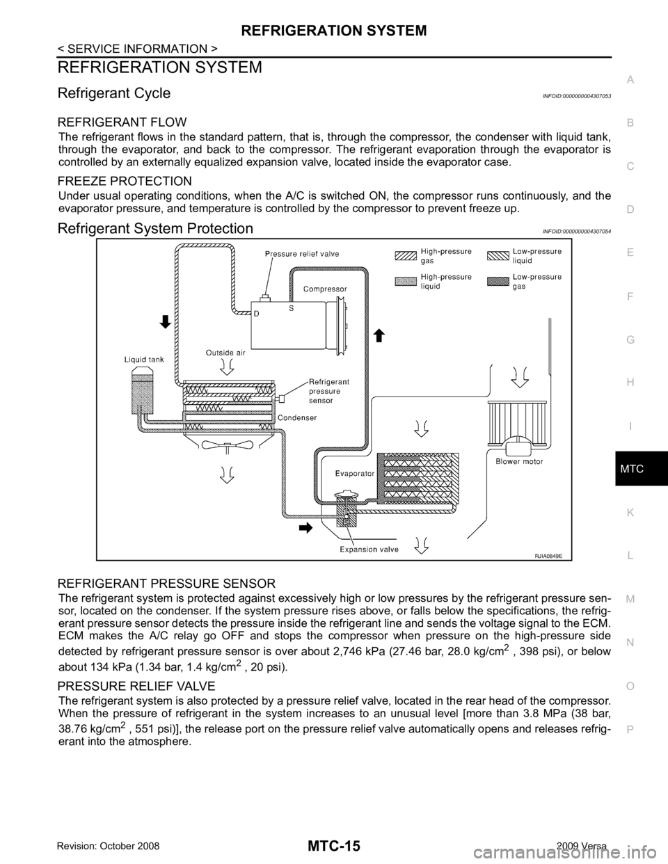
Refrigerant Cycle INFOID:0000000004307053
REFRIGERANT FLOW The refrigerant flows in the standard pattern, that is , through the compressor, the condenser with liquid tank,
through the evaporator, and back to the compressor. T he refrigerant evaporation through the evaporator is
controlled by an externally equalized expansion valve, located inside the evaporator case.
FREEZE PROTECTION Under usual operating conditions, when the A/C is s witched ON, the compressor runs continuously, and the
evaporator pressure, and temperature is controlled by the compressor to prevent freeze up.
Refrigerant System Protection INFOID:0000000004307054
REFRIGERANT PRESSURE SENSOR The refrigerant system is protected against excessively hi gh or low pressures by the refrigerant pressure sen-
sor, located on the condenser. If the system pressure rise s above, or falls below the specifications, the refrig-
erant pressure sensor detects the pressure inside t he refrigerant line and sends the voltage signal to the ECM.
ECM makes the A/C relay go OFF and stops the compressor when pressure on the high-pressure side
detected by refrigerant pressure sensor is over about 2,746 kPa (27.46 bar, 28.0 kg/cm 2
, 398 psi), or below
about 134 kPa (1.34 bar, 1.4 kg/cm 2
, 20 psi).
PRESSURE RELIEF VALVE The refrigerant system is also protected by a pressure relief valve, located in the rear head of the compressor.
When the pressure of refrigerant in the system in creases to an unusual level [more than 3.8 MPa (38 bar,
38.76 kg/cm 2
, 551 psi)], the release port on the pressure relief valve automatically opens and releases refrig-
erant into the atmosphere.
Page 3920 of 4331
![NISSAN LATIO 2009 Service Repair Manual MTC
N
O P
NG >> Check power supply circuit and 15A fuses [Nos. 15 and 17, located in the fuse block (J/B)].
Refer to PG-3, " Schematic " .
• If fuses are OK, reinstall fuses and GO T NISSAN LATIO 2009 Service Repair Manual MTC
N
O P
NG >> Check power supply circuit and 15A fuses [Nos. 15 and 17, located in the fuse block (J/B)].
Refer to PG-3, " Schematic " .
• If fuses are OK, reinstall fuses and GO T](/manual-img/5/57359/w960_57359-3919.png)
MTC
N
O P
NG >> Check power supply circuit and 15A fuses [Nos. 15 and 17, located in the fuse block (J/B)].
Refer to PG-3, " Schematic " .
• If fuses are OK, reinstall fuses and GO TO 3.
• If fuses are NG, replace fuse and check harness for short circuit. Repair or replace if necessary. OK >> GO TO 4.
NG >> Repair harness or connector. OK >> GO TO 5.
NG >> Repair harness or connector. OK >> Replace blower motor relay.
NG >> Repair harness or connector. OK >> GO TO 7.
NG >> Replace front blower motor. Refer to MTC-62, " Removal
and Installation " .
Page 3984 of 4331

PG
N
O P
CONTENTS
POWER SUPPLY, GROUND & CIRCUIT ELEMENTS
SERVICE INFORMATION .. ..........................2
PRECAUTIONS .............................................. .....2
Precaution for Supplemental Restraint System
(SRS) "AIR BAG" and "SEAT BELT PRE-TEN-
SIONER" ............................................................. ......
2
POWER SUPPLY ROUTING CIRCUIT .......... .....3
Schematic ........................................................... ......3
Wiring Diagram - POWER - ................................ ......5
Fuse .................................................................... ....15
Fusible Link ......................................................... ....15
Circuit Breaker (Built Into BCM) .......................... ....15
Circuit Breaker .................................................... ....15
IPDM E/R (INTELLIGENT POWER DISTRI-
BUTION MODULE ENGINE ROOM) ............. ....16
System Description ............................................. ....16
CAN Communication System Description ........... ....17
Function of Detecting Igni tion Relay Malfunction ....17
CONSULT-III Function (IPDM E/R) ..................... ....17
Auto Active Test .................................................. ....19
IPDM E/R Terminal Arrangement - Type A ......... ....22
IPDM E/R Terminal Arrangement - Type B ......... ....23
Terminal and Reference Value for IPDM E/R ..... ....24
IPDM E/R Power/Ground Circuit Inspection ....... ....26
Inspection with CONSULT- III (Self-Diagnosis) .......27
Removal and Installation of IPDM E/R ....................27 GROUND CIRCUI
T ........................................... 29
Ground Distribution .............................................. ....29
HARNESS ................... ...................................... 38
Harness Layout ................................................... ....38
Wiring Diagram Codes (Cell Codes) ................... ....57
ELECTRICAL UNITS LOCATION .................... 60
Electrical Units Location ...................................... ....60
HARNESS CONNECTOR ................................. 64
Description ........................................................... ....64
ELECTRICAL UNITS ........................................ 67
Terminal Arrangement ......................................... ....67
STANDARDIZED RELAY ................................. 68
Description ........................................................... ....68
SUPER MULTIPLE JUNCTION (SMJ) ............. 70
Terminal Arrangement ......................................... ....70
FUSE BLOCK-JUNCTION BOX (J/B) .............. 72
Terminal Arrangement ......................................... ....72
FUSE AND FUSIBLE LINK BOX ...................... 73
Terminal Arrangement ......................................... ....73
Page 4000 of 4331
PG
N
O P
IPDM E/R STATUS CONTROL
In order to save power, IPDM E/R switches status by itself based on each operating condition.
1. CAN communication status • CAN communication is normally performed with other control units.
• Individual unit control by IPDM E/R is normally performed.
• When sleep request signal is received from BCM, mode is switched to sleep waiting status.
2. Sleep waiting status • Process to stop CAN communication is activated.
• All systems controlled by IPDM E/R are stopped. When 1 second has elapsed after CAN communica-
tion with other control units is st opped, mode switches to sleep status.
3. Sleep status • IPDM E/R operates in low current-consumption mode.
• CAN communication is stopped.
• When a change in CAN communication signal is detec ted, mode switches to CAN communication sta-
tus.
• When a change in ignition switch signal is detect ed, mode switches to CAN communication status.
CAN Communication System Description INFOID:0000000004306656
Refer to LAN-8, " System Diagram " .
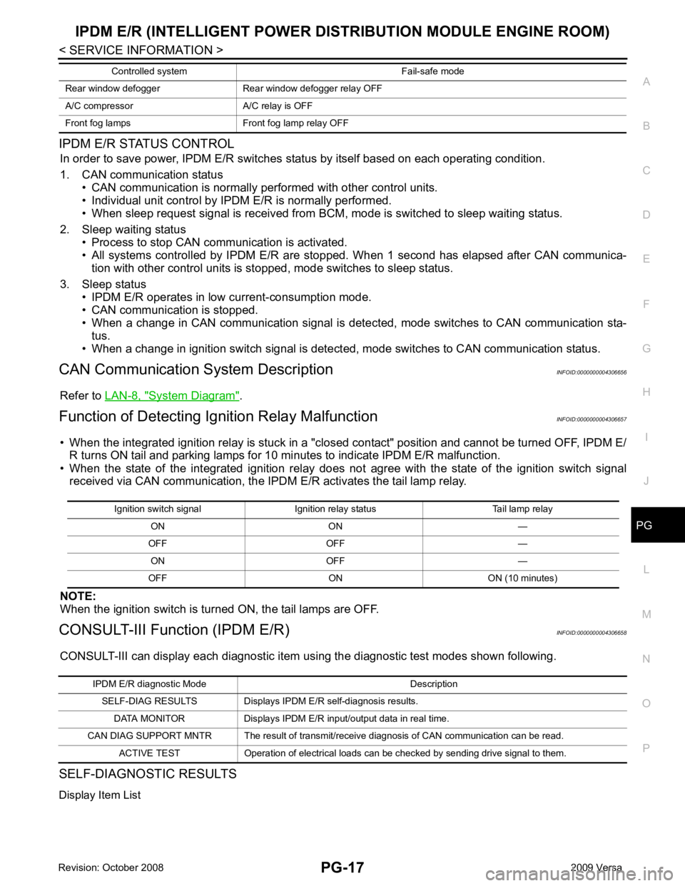
Function of Detecting Ig nition Relay Malfunction INFOID:0000000004306657
• When the integrated ignition relay is stuck in a "clo sed contact" position and cannot be turned OFF, IPDM E/
R turns ON tail and parking lamps for 10 mi nutes to indicate IPDM E/R malfunction.
• When the state of the integrated ignition relay does not agree with the state of the ignition switch signal
received via CAN communication, the IPDM E/R activates the tail lamp relay.
NOTE:
When the ignition switch is turned ON, the tail lamps are OFF.
CONSULT-III Function (IPDM E/R) INFOID:0000000004306658
CONSULT-III can display each diagnostic item using the diagnostic test modes shown following.
SELF-DIAGNOSTIC RESULTS
Display Item List Rear window defogger Rear window defogger relay OFF
A/C compressor A/C relay is OFF
Front fog lamps Front fog lamp relay OFF Controlled system Fail-safe mode Ignition switch signal Ignition relay status Tail lamp relay
ON ON —
OFF OFF — ON OFF —
OFF ON ON (10 minutes) IPDM E/R diagnostic Mode Description
SELF-DIAG RESULTS Displays IPDM E/R self-diagnosis results.
DATA MONITOR Displays IPDM E/R input/output data in real time.
CAN DIAG SUPPORT MNTR The result of transmit/receive diagnosis of CAN communication can be read. ACTIVE TEST Operation of electrical loads can be checked by sending drive signal to them.