2008 NISSAN TEANA maintenance
[x] Cancel search: maintenancePage 1896 of 5121

CAMSHAFT VALVE CLEARANCE
EM-21
< ON-VEHICLE MAINTENANCE >
C
D
E
F
G
H
I
J
K
L
MA
EM
N
P O
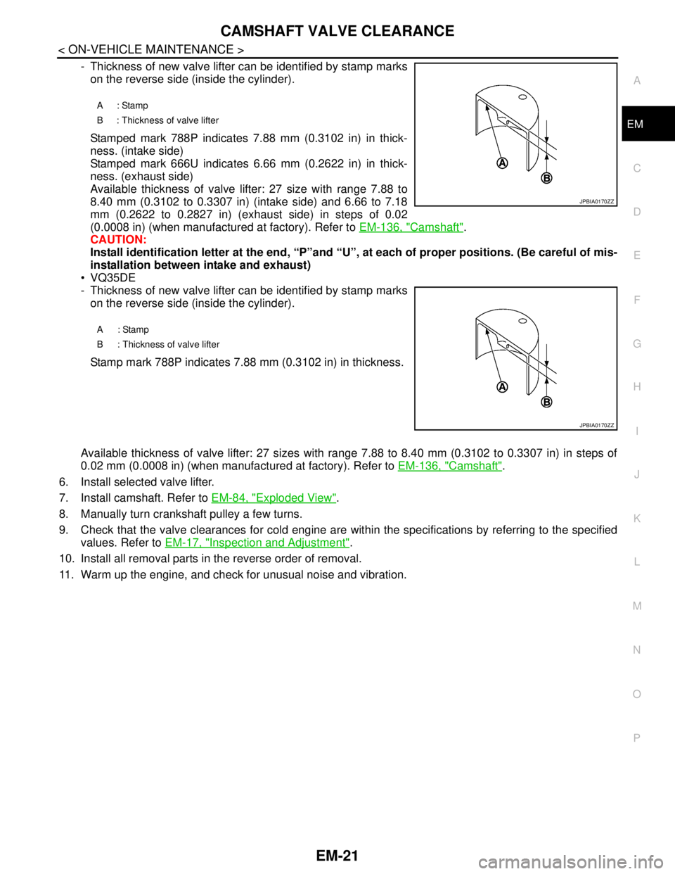
- Thickness of new valve lifter can be identified by stamp marks
on the reverse side (inside the cylinder).
Stamped mark 788P indicates 7.88 mm (0.3102 in) in thick-
ness. (intake side)
Stamped mark 666U indicates 6.66 mm (0.2622 in) in thick-
ness. (exhaust side)
Available thickness of valve lifter: 27 size with range 7.88 to
8.40 mm (0.3102 to 0.3307 in) (intake side) and 6.66 to 7.18
mm (0.2622 to 0.2827 in) (exhaust side) in steps of 0.02
(0.0008 in) (when manufactured at factory). Refer to EM-136, "
Camshaft".
CAUTION:
Install identification letter at the end, “P”and “U”, at each of proper positions. (Be careful of mis-
installation between intake and exhaust)
VQ35DE
- Thickness of new valve lifter can be identified by stamp marks
on the reverse side (inside the cylinder).
Stamp mark 788P indicates 7.88 mm (0.3102 in) in thickness.
Available thickness of valve lifter: 27 sizes with range 7.88 to 8.40 mm (0.3102 to 0.3307 in) in steps of
0.02 mm (0.0008 in) (when manufactured at factory). Refer to EM-136, "
Camshaft".
6. Install selected valve lifter.
7. Install camshaft. Refer to EM-84, "
Exploded View".
8. Manually turn crankshaft pulley a few turns.
9. Check that the valve clearances for cold engine are within the specifications by referring to the specified
values. Refer to EM-17, "
Inspection and Adjustment".
10. Install all removal parts in the reverse order of removal.
11. Warm up the engine, and check for unusual noise and vibration.
A: Stamp
B : Thickness of valve lifter
A: Stamp
B : Thickness of valve lifter
JPBIA0170ZZ
JPBIA0170ZZ
Page 1897 of 5121

EM-22
< ON-VEHICLE MAINTENANCE >
COMPRESSION PRESSURE
COMPRESSION PRESSURE
InspectionINFOID:0000000003802245
1. Warm up engine thoroughly. Then, stop it.
2. Release fuel pressure. Refer to EC-411, "
Inspection".
3. Disconnect fuel pump fuse to avoid fuel injection during measurement. Refer to EC-20,
"ComponentPartsLocation".
4. Remove engine cover. Refer to EM-24, "
Exploded View".
5. Remove ignition coil and spark plug from each cylinder. Refer to EM-49, "
Exploded View".
6. Connect engine tachometer (not required in use of CONSULT-III).
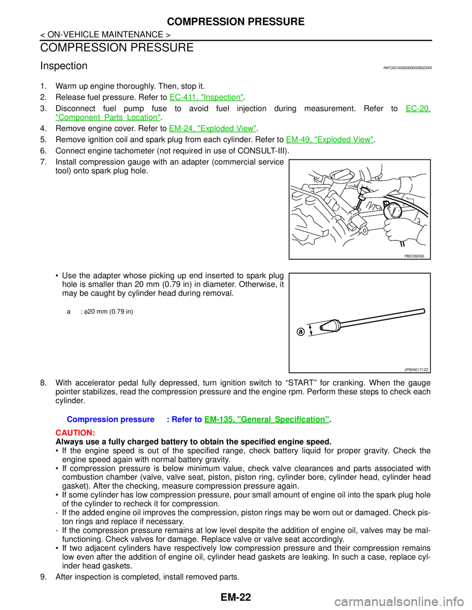
7. Install compression gauge with an adapter (commercial service
tool) onto spark plug hole.
Use the adapter whose picking up end inserted to spark plug
hole is smaller than 20 mm (0.79 in) in diameter. Otherwise, it
may be caught by cylinder head during removal.
8. With accelerator pedal fully depressed, turn ignition switch to “START” for cranking. When the gauge
pointer stabilizes, read the compression pressure and the engine rpm. Perform these steps to check each
cylinder.
CAUTION:
Always use a fully charged battery to obtain the specified engine speed.
If the engine speed is out of the specified range, check battery liquid for proper gravity. Check the
engine speed again with normal battery gravity.
If compression pressure is below minimum value, check valve clearances and parts associated with
combustion chamber (valve, valve seat, piston, piston ring, cylinder bore, cylinder head, cylinder head
gasket). After the checking, measure compression pressure again.
If some cylinder has low compression pressure, pour small amount of engine oil into the spark plug hole
of the cylinder to recheck it for compression.
- If the added engine oil improves the compression, piston rings may be worn out or damaged. Check pis-
ton rings and replace if necessary.
- If the compression pressure remains at low level despite the addition of engine oil, valves may be mal-
functioning. Check valves for damage. Replace valve or valve seat accordingly.
If two adjacent cylinders have respectively low compression pressure and their compression remains
low even after the addition of engine oil, cylinder head gaskets are leaking. In such a case, replace cyl-
inder head gaskets.
9. After inspection is completed, install removed parts.
PBIC0900E
a: φ20 mm (0.79 in)
JPBIA0171ZZ
Compression pressure : Refer to EM-135, "GeneralSpecification".
Page 1898 of 5121

COMPRESSION PRESSURE
EM-23
< ON-VEHICLE MAINTENANCE >
C
D
E
F
G
H
I
J
K
L
MA
EM
N
P O
10. Start the engine, and check that the engine runs smoothly.
11. Perform trouble diagnosis. If DTC appears, erase it. Refer to EC-124, "
Description".
Page 2024 of 5121

EX-1
ENGINE
C
DE
F
G H
I
J
K L
M
SECTION EX
A
EX
N
O P
CONTENTS
EXHAUST SYSTEM
PRECAUTION ................ ...............................2
PRECAUTIONS .............................................. .....2
Removal and Installation ..................................... ......2
PREPARATION ............................................3
PREPARATION .............................................. .....3
Commercial Service Tool .................................... ......3
ON-VEHICLE MAINTENANCE .....................4
EXHAUST SYSTEM ...........................................4
Inspection ............................................................ .....4
ON-VEHICLE REPAIR ..................................5
EXHAUST SYSTEM ...........................................5
Exploded View ..................................................... .....5
Removal and Installation ..........................................5
Inspection .................................................................6
Page 2027 of 5121

EX-4
< ON-VEHICLE MAINTENANCE >
EXHAUST SYSTEM
ON-VEHICLE MAINTENANCE
EXHAUST SYSTEM
InspectionINFOID:0000000003793260
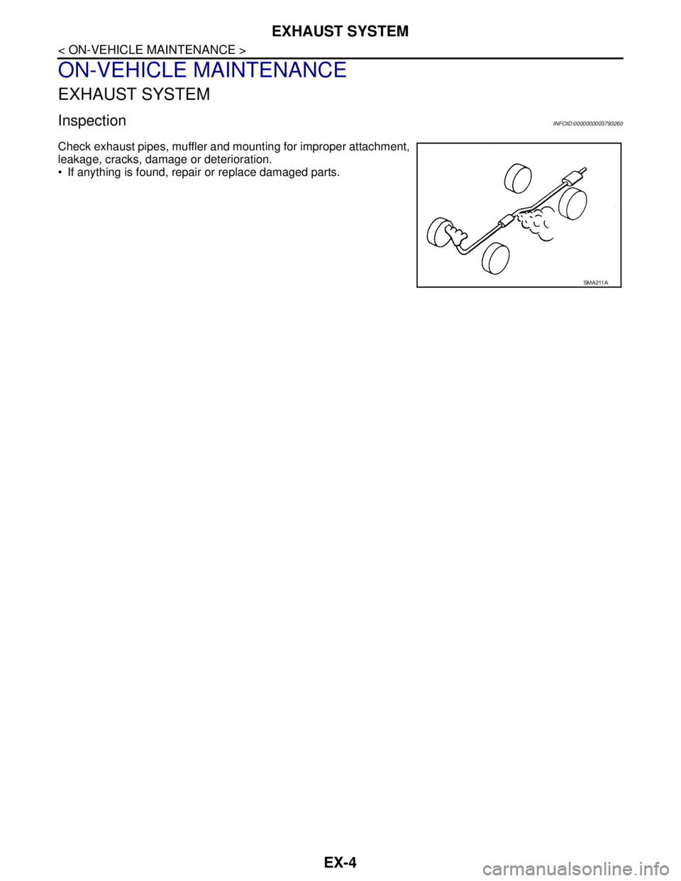
Check exhaust pipes, muffler and mounting for improper attachment,
leakage, cracks, damage or deterioration.
• If anything is found, repair or replace damaged parts.
SMA211A
Page 2032 of 5121

EXL-3
C
D
E
F
G
H
I
J
K
MA
B
EXL
N
O
P
TAIL LAMP CIRCUIT .........................................74
Component Function Check ....................................74
Diagnosis Procedure ...............................................74
LICENSE PLATE LAMP CIRCUIT .....................76
Component Function Check ....................................76
Diagnosis Procedure ...............................................76
REAR FOG LAMP CIRCUIT ..............................77
Component Function Check ....................................77
Diagnosis Procedure ...............................................77
HEADLAMP SYSTEM ........................................79
Wiring Diagram - HEADLAMP - ..............................79
AUTO LIGHT SYSTEM ......................................83
Wiring Diagram - AUTO LIGHT SYSTEM - .............83
FRONT FOG LAMP SYSTEM ............................87
Wiring Diagram - FRONT FOG LAMP - ..................87
TURN SIGNAL AND HAZARD WARNING
LAMP SYSTEM ..................................................
90
Wiring Diagram - TURN AND HAZARD WARN-
ING LAMPS - ..........................................................
90
PARKING, LICENSE PLATE AND TAIL
LAMPS SYSTEM ................................................
95
Wiring Diagram - PARKING, LICENSE PLATE
AND TAIL LAMPS - .................................................
95
STOP LAMP .......................................................99
Wiring Diagram - STOP LAMP - .............................99
BACK-UP LAMP ..............................................102
Wiring Diagram - BACK-UP LAMP - .....................102
REAR FOG LAMP SYSTEM ............................105
Wiring Diagram - REAR FOG LAMP - ..................105
ECU DIAGNOSIS .......................................108
BCM (BODY CONTROL MODULE) .................108
Reference Value ...................................................108
Wiring Diagram - BCM - ........................................131
Fail-safe ................................................................137
DTC Inspection Priority Chart .............................139
DTC Index ............................................................140
IPDM E/R (INTELLIGENT POWER DISTRI-
BUTION MODULE ENGINE ROOM) ...............
142
Reference Value ...................................................142
Wiring Diagram - IPDM E/R - ................................150
Fail-safe ................................................................153
DTC Index ............................................................155
AUTO LEVELIZER CONTROL UNIT ...............156
Reference Value ...................................................156
Wiring Diagram — HEADLAMP AIMING CON-
TROL SYSTEM — ................................................
158
Fail-safe ................................................................161
DTC Inspection Priority Chart ...............................162
DTC Index .............................................................163
SYMPTOM DIAGNOSIS ............................164
EXTERIOR LIGHTING SYSTEM SYMPTOMS .164
Symptom Table .....................................................164
NORMAL OPERATING CONDITION .............167
Description .............................................................167
BOTH SIDE HEADLAMPS (HI) ARE NOT
TURNED ON ...................................................
168
Description .............................................................168
Diagnosis Procedure .............................................168
BOTH SIDE HEADLAMPS (LO) ARE NOT
TURNED ON ...................................................
169
Description .............................................................169
Diagnosis Procedure .............................................169
PARKING, LICENSE PLATE AND TAIL
LAMPS ARE NOT TURNED ON .....................
170
Description .............................................................170
Diagnosis Procedure .............................................170
BOTH SIDE FRONT FOG LAMPS ARE NOT
TURNED ON ...................................................
171
Description .............................................................171
Diagnosis Procedure .............................................171
PRECAUTION ............................................172
PRECAUTIONS ...............................................172
Precaution for Supplemental Restraint System
(SRS) "AIR BAG" and "SEAT BELT PRE-TEN-
SIONER" ...............................................................
172
Precautions For Xenon Headlamp Service ...........172
ON-VEHICLE MAINTENANCE ..................173
HEADLAMP AIMING ADJUSTMENT .............173
Description .............................................................173
Aiming Adjustment Procedure (Low Beam) ...........174
Aiming Adjustment Procedure (High Beam) ..........175
FRONT FOG LAMP AIMING ADJUSTMENT .178
Description .............................................................178
Aiming Adjustment Procedure ...............................178
ON-VEHICLE REPAIR ...............................180
FRONT COMBINATION LAMP ......................180
Exploded View .......................................................180
Removal and Installation .......................................181
Replacement .........................................................181
Disassembly and Assembly ...................................182
FRONT FOG LAMP ........................................183
Exploded View .......................................................183
Removal and Installation .......................................183
Replacement .........................................................183
Page 2035 of 5121

EXL-6
BOTH SIDE FRONT FOG LAMPS ARE NOT
TURNED ON ....................................................
334
Description .............................................................334
Diagnosis Procedure .............................................334
PRECAUTION ............................................335
PRECAUTIONS ...............................................335
Precaution for Supplemental Restraint System
(SRS) "AIR BAG" and "SEAT BELT PRE-TEN-
SIONER" ................................................................
335
ON-VEHICLE MAINTENANCE ..................336
HEADLAMP AIMING ADJUSTMENT .............336
Description .............................................................336
Aiming Adjustment Procedure (Low Beam) ...........337
Aiming Adjustment Procedure (High Beam) ..........338
FRONT FOG LAMP AIMING ADJUSTMENT .341
Description .............................................................341
Aiming Adjustment Procedure ...............................341
ON-VEHICLE REPAIR ...............................343
FRONT COMBINATION LAMP .......................343
Exploded View .......................................................343
Removal and Installation .......................................343
Replacement .........................................................344
Disassembly and Assembly ...................................344
FRONT FOG LAMP .........................................346
Exploded View .......................................................346
Removal and Installation .......................................346
Replacement .........................................................346
OPTICAL SENSOR .........................................348
Exploded View .......................................................348
Removal and Installation .......................................348
LIGHTING & TURN SIGNAL SWITCH ............349
Exploded View ......................................................349
Removal and Installation .......................................349
HEADLAMP AIMING SWITCH .........................350
Exploded View ......................................................350
Removal and Installation .......................................350
HAZARD SWITCH ............................................351
Exploded View ......................................................351
Removal and Installation .......................................351
SIDE TURN SIGNAL LAMP .............................352
Exploded View ......................................................352
Removal and Installation .......................................352
REAR COMBINATION LAMP ..........................354
Exploded View ......................................................354
Removal and Installation .......................................354
Replacement .........................................................355
HIGH-MOUNTED STOP LAMP ........................356
Exploded View ......................................................356
Removal and Installation .......................................356
REAR FOG LAMP ............................................357
Exploded View ......................................................357
Removal and Installation .......................................357
Replacement .........................................................357
LICENSE PLATE LAMP ...................................358
Exploded View ......................................................358
Removal and Installation .......................................358
Replacement .........................................................358
SERVICE DATA AND SPECIFICATIONS
(SDS) .........................................................
360
SERVICE DATA AND SPECIFICATIONS
(SDS) ................................................................
360
Bulb Specifications ................................................360
Page 2201 of 5121
![NISSAN TEANA 2008 Service Manual EXL-172
< PRECAUTION >[XENON TYPE]
PRECAUTIONS
PRECAUTION
PRECAUTIONS
Precaution for Supplemental Restraint System (SRS) "AIR BAG" and "SEAT BELT
PRE-TENSIONER"
INFOID:0000000003813382
The Supplement NISSAN TEANA 2008 Service Manual EXL-172
< PRECAUTION >[XENON TYPE]
PRECAUTIONS
PRECAUTION
PRECAUTIONS
Precaution for Supplemental Restraint System (SRS) "AIR BAG" and "SEAT BELT
PRE-TENSIONER"
INFOID:0000000003813382
The Supplement](/manual-img/5/57391/w960_57391-2200.png)
EXL-172
< PRECAUTION >[XENON TYPE]
PRECAUTIONS
PRECAUTION
PRECAUTIONS
Precaution for Supplemental Restraint System (SRS) "AIR BAG" and "SEAT BELT
PRE-TENSIONER"
INFOID:0000000003813382
The Supplemental Restraint System such as “AIR BAG” and “SEAT BELT PRE-TENSIONER”, used along
with a front seat belt, helps to reduce the risk or severity of injury to the driver and front passenger for certain
types of collision. This system includes seat belt switch inputs and dual stage front air bag modules. The SRS
system uses the seat belt switches to determine the front air bag deployment, and may only deploy one front
air bag, depending on the severity of a collision and whether the front occupants are belted or unbelted.
Information necessary to service the system safely is included in the “SRS AIRBAG” and “SEAT BELT” of this
Service Manual.
WARNING:
To avoid rendering the SRS inoperative, which could increase the risk of personal injury or death in
the event of a collision which would result in air bag inflation, all maintenance must be performed by
an authorized NISSAN/INFINITI dealer.
Improper maintenance, including incorrect removal and installation of the SRS, can lead to personal
injury caused by unintentional activation of the system. For removal of Spiral Cable and Air Bag
Module, see the “SRS AIRBAG”.
Do not use electrical test equipment on any circuit related to the SRS unless instructed to in this
Service Manual. SRS wiring harnesses can be identified by yellow and/or orange harnesses or har-
ness connectors.
Precautions For Xenon Headlamp ServiceINFOID:0000000003773614
WARNING:
Comply with the following warnings to prevent any serious accident.
Disconnect the battery cable (negative terminal) or the power supply fuse before installing, remov-
ing, or touching the xenon headlamp (bulb included). The xenon headlamp contains high-voltage
generated parts.
Never work with wet hands.
Check the xenon headlamp ON-OFF status after assembling it to the vehicle. Never turn the xenon
headlamp ON in other conditions. Connect the power supply to the vehicle-side connector.
(Turning it ON outside the lamp case may cause fire or visual impairments.)
Never touch the bulb glass immediately after turning it OFF. It is extremely hot.
CAUTION:
Comply with the following cautions to prevent any error and malfunction.
Install the xenon bulb securely. (Insufficient bulb socket installation may melt the bulb, the connec-
tor, the housing, etc. by high-voltage leakage or corona discharge.)
Never perform HID circuit inspection with a tester.
Never touch the xenon bulb glass with hands. Never put oil and grease on it.
Dispose of the used xenon bulb after packing it in thick vinyl without breaking it.
Never wipe out dirt and contamination with organic solvent (thinner, gasoline, etc.).