Page 4882 of 5121
![NISSAN TEANA 2008 Service Manual COMPRESSOR
VTL-71
< PRECAUTION >[WITH 7 INCH DISPLAY]
C
D
E
F
G
H
J
K
L
MA
B
VTL
N
O
P
COMPRESSOR
General PrecautionsINFOID:0000000003894453
CAUTION:
Plug all openings to prevent moisture and foreig NISSAN TEANA 2008 Service Manual COMPRESSOR
VTL-71
< PRECAUTION >[WITH 7 INCH DISPLAY]
C
D
E
F
G
H
J
K
L
MA
B
VTL
N
O
P
COMPRESSOR
General PrecautionsINFOID:0000000003894453
CAUTION:
Plug all openings to prevent moisture and foreig](/manual-img/5/57391/w960_57391-4881.png)
COMPRESSOR
VTL-71
< PRECAUTION >[WITH 7 INCH DISPLAY]
C
D
E
F
G
H
J
K
L
MA
B
VTL
N
O
P
COMPRESSOR
General PrecautionsINFOID:0000000003894453
CAUTION:
Plug all openings to prevent moisture and foreign matter from entering.
Store it in the same way at it is when mounted on the car when the compressor is removed.
Follow “Maintenance of Lubricant Quantity in Compressor” exactly when replacing or repairing
compressor. Refer to HA-28, "
Maintenance of Lubricant Quantity".
Keep friction surfaces between clutch and pulley clean. Wipe it off by using a clean waste cloth
moistened with thinner if the surface is contaminated with lubricant.
Turn the compressor shaft by hand more than five turns in both directions after compressor service
operation. This distributes equally lubricant inside the compressor. Let the engine idle and operate
the compressor for one hour after the compressor is installed.
Apply voltage to the new one and check for normal operation after replacing the compressor magnet
clutch.
Page 4888 of 5121
AIR CONDITIONER FILTER
VTL-77
< ON-VEHICLE MAINTENANCE >[WITH 7 INCH DISPLAY]
C
D
E
F
G
H
J
K
L
MA
B
VTL
N
O
P
ON-VEHICLE MAINTENANCE
AIR CONDITIONER FILTER
Exploded ViewINFOID:0000000003894471
Removal and InstallationINFOID:0000000003894472
REMOVAL
1. Remove filter cover (1), and then remove air conditioner filter
(2).
INSTALLATION
Installation is basically the reverse order of removal.
CAUTION:
If the filter is deformed/damaged when removing, replace it with a new one. Deformed/damaged filter
may deteriorate the duct collecting performance.
When installing, handle the filter with extreme care to avoid deforming/damaging.
ReplacementINFOID:0000000003894473
Replace air conditioner filter.
Refer to MA-6, "
Periodic Maintenance".
Affix a caution label inside the glove box when replacing filter.
1. Heater & cooling unit assembly 2. Air conditioner filter 3. Filter cover
JPIIA0895ZZ
JPIIA0896ZZ
Page 5007 of 5121

WCS
PRECAUTIONS
WCS-77
< PRECAUTION >
C
D
E
F
G
H
I
J
K
L
MB A
O
P
PRECAUTION
PRECAUTIONS
Precaution for Supplemental Restraint System (SRS) "AIR BAG" and "SEAT BELT
PRE-TENSIONER"
INFOID:0000000003940982
The Supplemental Restraint System such as “AIR BAG” and “SEAT BELT PRE-TENSIONER”, used along
with a front seat belt, helps to reduce the risk or severity of injury to the driver and front passenger for certain
types of collision. Information necessary to service the system safely is included in the “SRS AIRBAG” and
“SEAT BELT” of this Service Manual.
WARNING:
• To avoid rendering the SRS inoperative, which could increase the risk of personal injury or death in
the event of a collision which would result in air bag inflation, all maintenance must be performed by
an authorized NISSAN/INFINITI dealer.
Improper maintenance, including incorrect removal and installation of the SRS, can lead to personal
injury caused by unintentional activation of the system. For removal of Spiral Cable and Air Bag
Module, see the “SRS AIRBAG”.
Never use electrical test equipment on any circuit related to the SRS unless instructed to in this Ser-
vice Manual. SRS wiring harnesses can be identified by yellow and/or orange harnesses or harness
connectors.
Page 5009 of 5121

WT-2
< ON-VEHICLE MAINTENANCE >
ROAD WHEEL
ON-VEHICLE MAINTENANCE
ROAD WHEEL
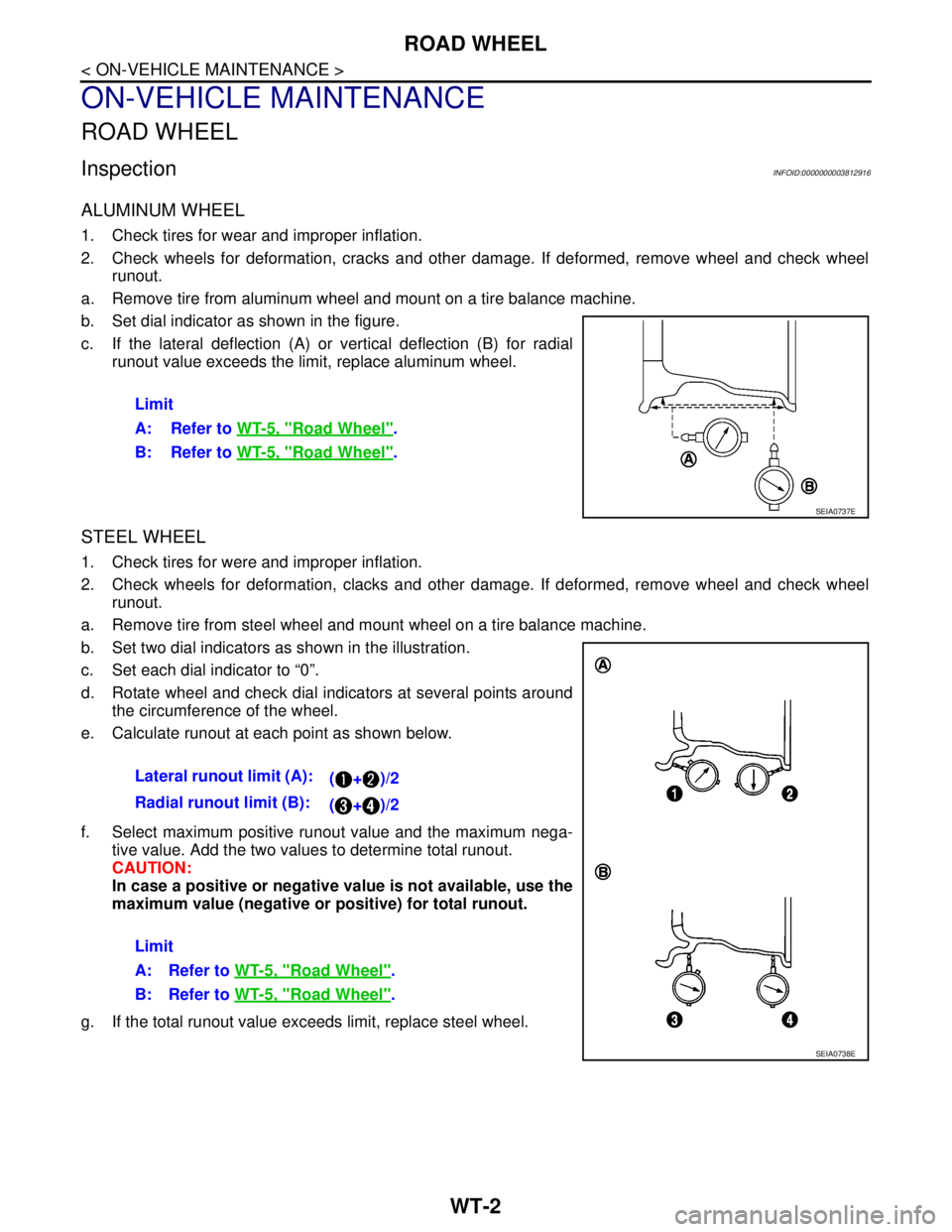
InspectionINFOID:0000000003812916
ALUMINUM WHEEL
1. Check tires for wear and improper inflation.
2. Check wheels for deformation, cracks and other damage. If deformed, remove wheel and check wheel
runout.
a. Remove tire from aluminum wheel and mount on a tire balance machine.
b. Set dial indicator as shown in the figure.
c. If the lateral deflection (A) or vertical deflection (B) for radial
runout value exceeds the limit, replace aluminum wheel.
STEEL WHEEL
1. Check tires for were and improper inflation.
2. Check wheels for deformation, clacks and other damage. If deformed, remove wheel and check wheel
runout.
a. Remove tire from steel wheel and mount wheel on a tire balance machine.
b. Set two dial indicators as shown in the illustration.
c. Set each dial indicator to “0”.
d. Rotate wheel and check dial indicators at several points around
the circumference of the wheel.
e. Calculate runout at each point as shown below.
f. Select maximum positive runout value and the maximum nega-
tive value. Add the two values to determine total runout.
CAUTION:
In case a positive or negative value is not available, use the
maximum value (negative or positive) for total runout.
g. If the total runout value exceeds limit, replace steel wheel.Limit
A: Refer to WT-5, "
Road Wheel".
B: Refer to WT-5, "
Road Wheel".
SEIA0737E
Lateral runout limit (A):
(+)/2
Radial runout limit (B):
(+)/2
Limit
A: Refer to WT-5, "
Road Wheel".
B: Refer to WT-5, "
Road Wheel".
SEIA0738E
Page 5011 of 5121

WT-4
< ON-VEHICLE REPAIR >
ROAD WHEEL TIRE ASSEMBLY
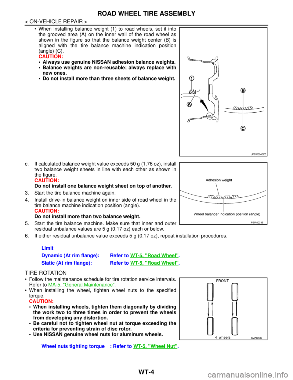
When installing balance weight (1) to road wheels, set it into
the grooved area (A) on the inner wall of the road wheel as
shown in the figure so that the balance weight center (B) is
aligned with the tire balance machine indication position
(angle) (C).
CAUTION:
Always use genuine NISSAN adhesion balance weights.
Balance weights are non-reusable; always replace with
new ones.
Do not install more than three sheets of balance weight.
c. If calculated balance weight value exceeds 50 g (1.76 oz), install
two balance weight sheets in line with each other as shown in
the figure.
CAUTION:
Do not install one balance weight sheet on top of another.
3. Start the tire balance machine again.
4. Install drive-in balance weight on inner side of road wheel in the
tire balance machine indication position (angle).
CAUTION:
Do not install more than two balance weight.
5. Start the tire balance machine. Make sure that inner and outer
residual unbalance values are 5 g (0.17 oz) each or below.
6. If either residual unbalance value exceeds 5 g (0.17 oz), repeat installation procedures.
TIRE ROTATION
Follow the maintenance schedule for tire rotation service intervals.
Refer to MA-5, "
General Maintenance".
When installing the wheel, tighten wheel nuts to the specified
torque.
CAUTION:
When installing wheels, tighten them diagonally by dividing
the work two to three times in order to prevent the wheels
from developing any distortion.
Be careful not to tighten wheel nut at torque exceeding the
criteria for preventing strain of disc rotor.
Use NISSAN genuine wheel nuts for aluminum wheels.
JPEIC0040ZZ
Limit
Dynamic (At rim flange): Refer to WT-5, "
Road Wheel".
Static (At rim flange): Refer to WT-5, "
Road Wheel".
PEIA0033E
Wheel nuts tighting torque : Refer to WT-5, "Wheel Nut".
SMA829C
Page 5108 of 5121

WW-96
< PRECAUTION >
PRECAUTIONS
PRECAUTION
PRECAUTIONS
Precaution for Supplemental Restraint System (SRS) "AIR BAG" and "SEAT BELT
PRE-TENSIONER"
INFOID:0000000003761618
The Supplemental Restraint System such as “AIR BAG” and “SEAT BELT PRE-TENSIONER”, used along
with a front seat belt, helps to reduce the risk or severity of injury to the driver and front passenger for certain
types of collision. This system includes seat belt switch inputs and dual stage front air bag modules. The SRS
system uses the seat belt switches to determine the front air bag deployment, and may only deploy one front
air bag, depending on the severity of a collision and whether the front occupants are belted or unbelted.
Information necessary to service the system safely is included in the “SRS AIRBAG” and “SEAT BELT” of this
Service Manual.
WARNING:
To avoid rendering the SRS inoperative, which could increase the risk of personal injury or death in
the event of a collision which would result in air bag inflation, all maintenance must be performed by
an authorized NISSAN/INFINITI dealer.
Improper maintenance, including incorrect removal and installation of the SRS, can lead to personal
injury caused by unintentional activation of the system. For removal of Spiral Cable and Air Bag
Module, see the “SRS AIRBAG”.
Never use electrical test equipment on any circuit related to the SRS unless instructed to in this Ser-
vice Manual. SRS wiring harnesses can be identified by yellow and/or orange harnesses or harness
connectors.
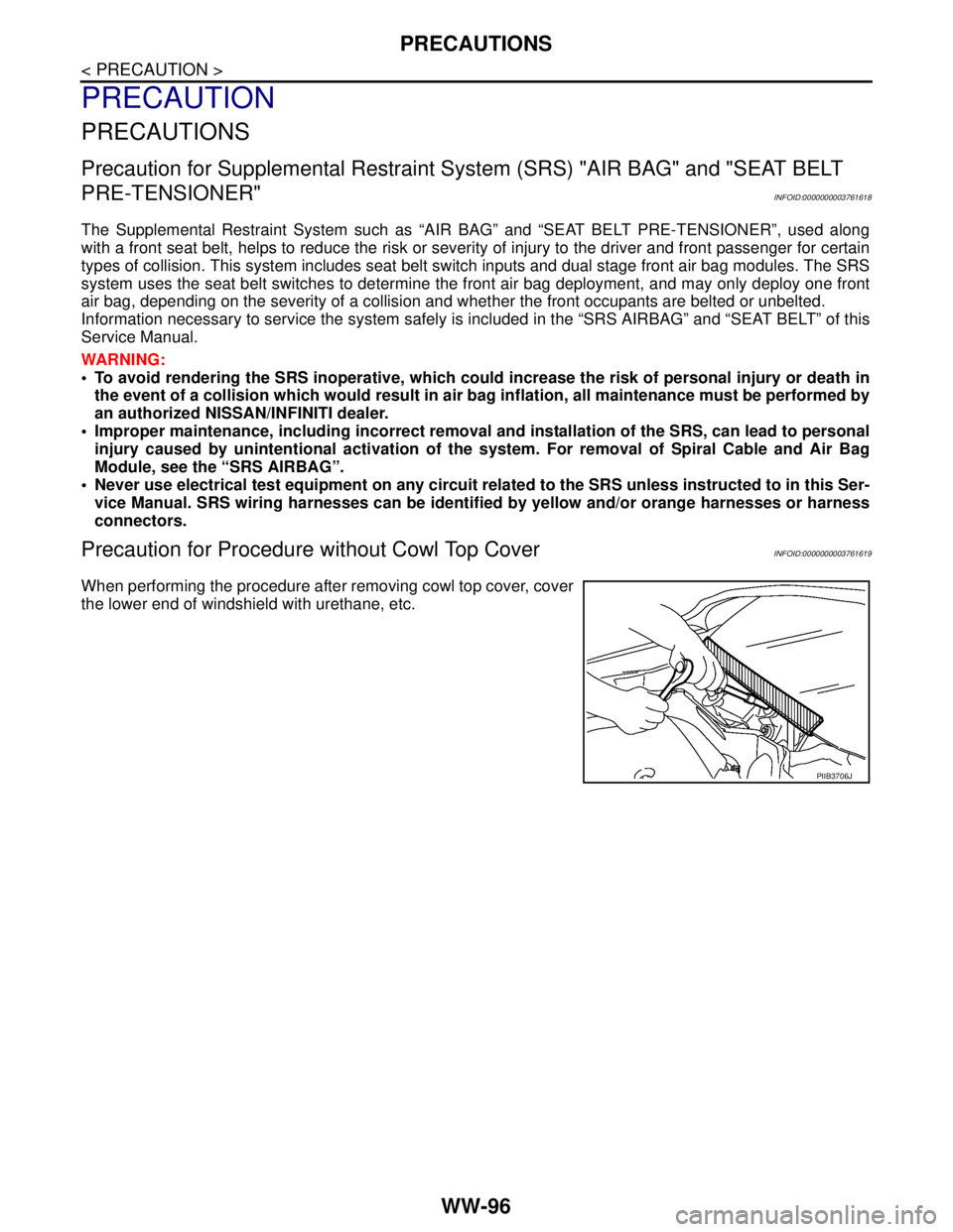
Precaution for Procedure without Cowl Top CoverINFOID:0000000003761619
When performing the procedure after removing cowl top cover, cover
the lower end of windshield with urethane, etc.
PIIB3706J