2008 NISSAN TEANA alternator belt
[x] Cancel search: alternator beltPage 1099 of 5121
CHG
CHG-1
ELECTRICAL & POWER CONTROL
C
DE
F
G H
I
J
K L
B
SECTION CHG
A
O P
N
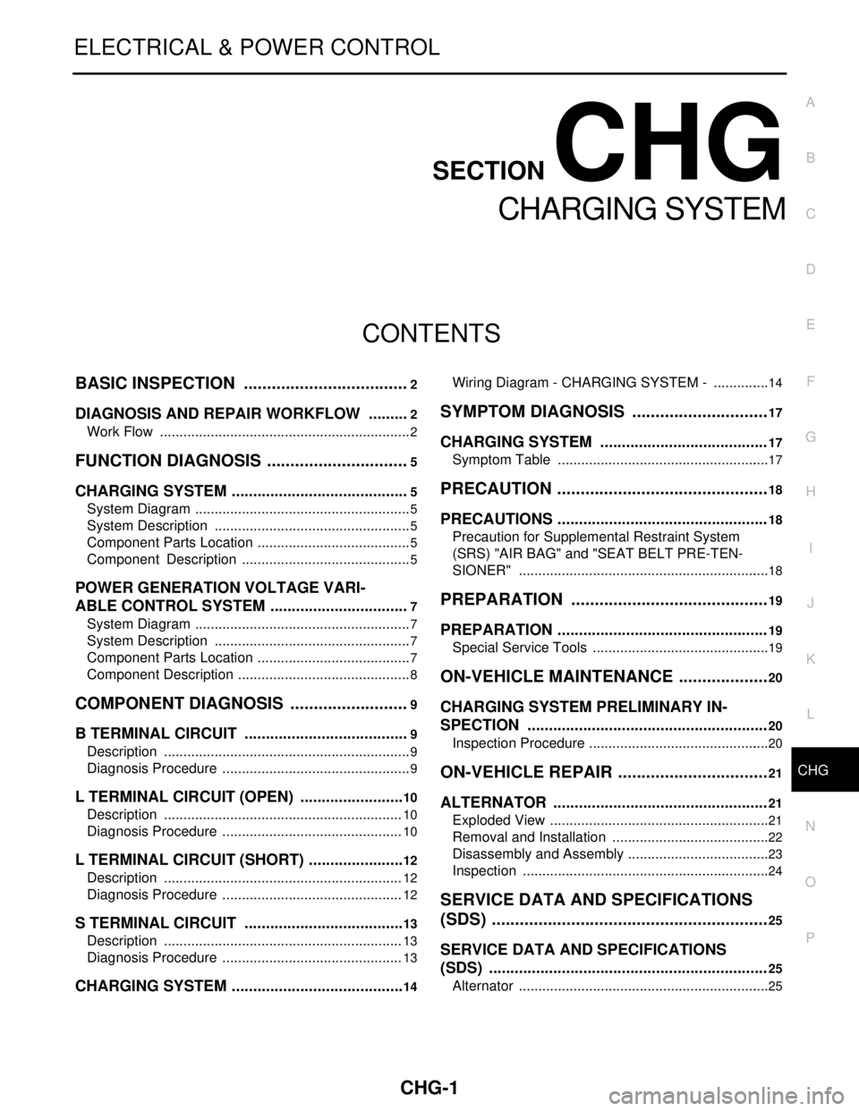
CONTENTS
CHARGING SYSTEM
BASIC INSPECTION .......
.............................2
DIAGNOSIS AND REPAIR WORKFLOW ..... .....2
Work Flow ........................................................... ......2
FUNCTION DIAGNOSIS ...............................5
CHARGING SYSTEM ..................................... .....5
System Diagram .................................................. ......5
System Description ...................................................5
Component Parts Location ........................................5
Component Description ............................................5
POWER GENERATION VOLTAGE VARI-
ABLE CONTROL SYSTEM ............................ .....
7
System Diagram .................................................. ......7
System Description ...................................................7
Component Parts Location ........................................7
Component Description .............................................8
COMPONENT DIAGNOSIS ..........................9
B TERMINAL CIRCUIT .................................. .....9
Description .......................................................... ......9
Diagnosis Procedure .................................................9
L TERMINAL CIRCUIT (OPEN) .........................10
Description .......................................................... ....10
Diagnosis Procedure ...............................................10
L TERMINAL CIRCUIT (SHORT) .......................12
Description .......................................................... ....12
Diagnosis Procedure ...............................................12
S TERMINAL CIRCUIT ......................................13
Description .......................................................... ....13
Diagnosis Procedure ...............................................13
CHARGING SYSTEM ..................................... ....14
Wiring Diagram - CHARGING SYSTEM - ........... ....14
SYMPTOM DIAGNOSIS ..............................17
CHARGING SYSTEM .......................................17
Symptom Table ................................................... ....17
PRECAUTION ..............................................18
PRECAUTIONS .................................................18
Precaution for Supplemental Restraint System
(SRS) "AIR BAG" and "SEAT BELT PRE-TEN-
SIONER" ............................................................. ....
18
PREPARATION ...........................................19
PREPARATION .................................................19
Special Service Tools .......................................... ....19
ON-VEHICLE MAINTENANCE ....................20
CHARGING SYSTEM PRELIMINARY IN-
SPECTION ....... ................................ .................
20
Inspection Procedure ........................................... ....20
ON-VEHICLE REPAIR .................................21
ALTERNATOR . ................................ .................21
Exploded View ..................................................... ....21
Removal and Installation .........................................22
Disassembly and Assembly .....................................23
Inspection ................................................................24
SERVICE DATA AND SPECIFICATIONS
(SDS) ............... .............................................
25
SERVICE DATA AND SPECIFICATIONS
(SDS) .................................................................
25
Alternator ............................................................. ....25
Page 1118 of 5121
CHG-20
< ON-VEHICLE MAINTENANCE >
CHARGING SYSTEM PRELIMINARY INSPECTION
ON-VEHICLE MAINTENANCE
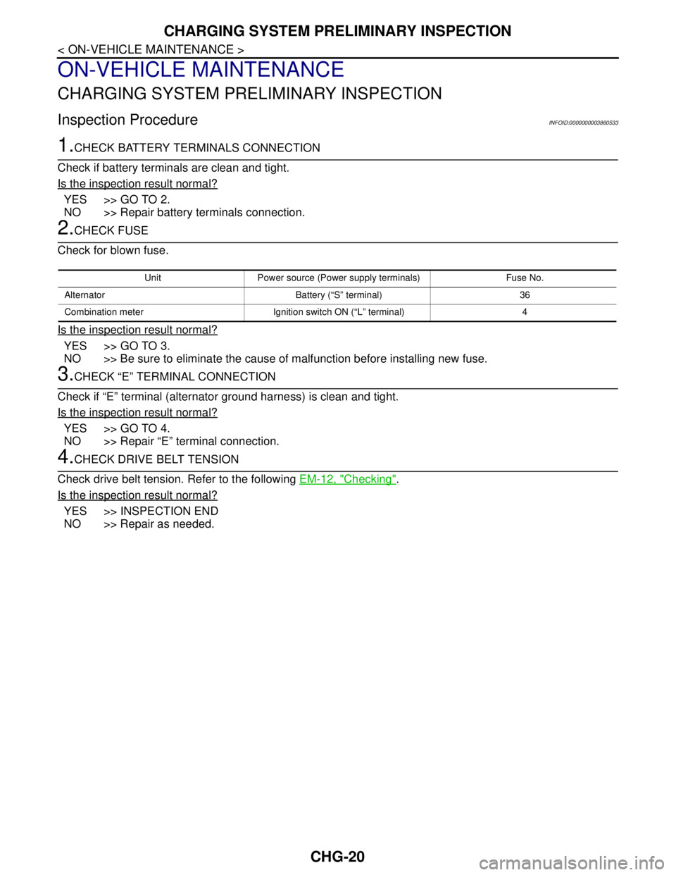
CHARGING SYSTEM PRELIMINARY INSPECTION
Inspection ProcedureINFOID:0000000003860533
1.CHECK BATTERY TERMINALS CONNECTION
Check if battery terminals are clean and tight.
Is the inspection result normal?
YES >> GO TO 2.
NO >> Repair battery terminals connection.
2.CHECK FUSE
Check for blown fuse.
Is the inspection result normal?
YES >> GO TO 3.
NO >> Be sure to eliminate the cause of malfunction before installing new fuse.
3.CHECK “E” TERMINAL CONNECTION
Check if “E” terminal (alternator ground harness) is clean and tight.
Is the inspection result normal?
YES >> GO TO 4.
NO >> Repair “E” terminal connection.
4.CHECK DRIVE BELT TENSION
Check drive belt tension. Refer to the following EM-12, "
Checking".
Is the inspection result normal?
YES >> INSPECTION END
NO >> Repair as needed.
Unit Power source (Power supply terminals) Fuse No.
Alternator Battery (“S” terminal) 36
Combination meter Ignition switch ON (“L” terminal) 4
Page 1120 of 5121
CHG-22
< ON-VEHICLE REPAIR >
ALTERNATOR
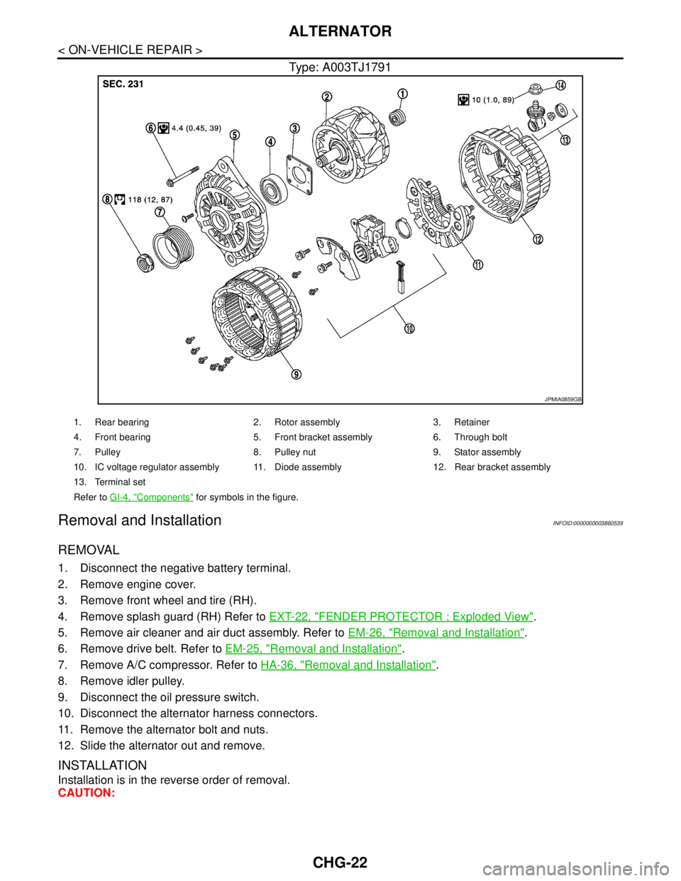
Type: A003TJ1791
Removal and InstallationINFOID:0000000003860539
REMOVAL
1. Disconnect the negative battery terminal.
2. Remove engine cover.
3. Remove front wheel and tire (RH).
4. Remove splash guard (RH) Refer to EXT-22, "
FENDER PROTECTOR : Exploded View".
5. Remove air cleaner and air duct assembly. Refer to EM-26, "
Removal and Installation".
6. Remove drive belt. Refer to EM-25, "
Removal and Installation".
7. Remove A/C compressor. Refer to HA-36, "
Removal and Installation".
8. Remove idler pulley.
9. Disconnect the oil pressure switch.
10. Disconnect the alternator harness connectors.
11. Remove the alternator bolt and nuts.
12. Slide the alternator out and remove.
INSTALLATION
Installation is in the reverse order of removal.
CAUTION:
JPMIA0859GB
1. Rear bearing 2. Rotor assembly 3. Retainer
4. Front bearing 5. Front bracket assembly 6. Through bolt
7. Pulley 8. Pulley nut 9. Stator assembly
10. IC voltage regulator assembly 11. Diode assembly 12. Rear bracket assembly
13. Terminal set
Refer to GI-4, "
Components" for symbols in the figure.
Page 1121 of 5121
CHG
ALTERNATOR
CHG-23
< ON-VEHICLE REPAIR >
C
D
E
F
G
H
I
J
K
L B A
O
P N
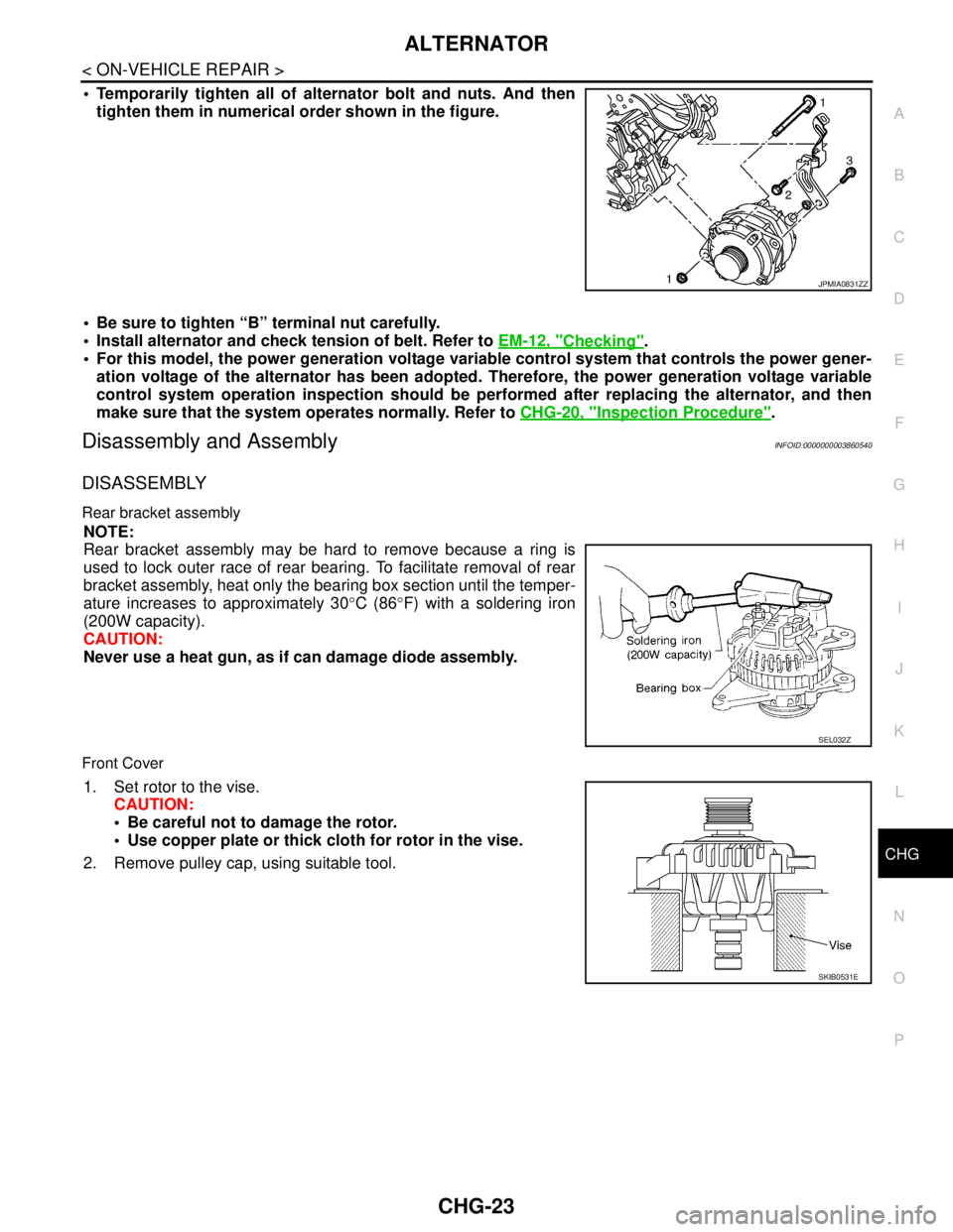
Temporarily tighten all of alternator bolt and nuts. And then
tighten them in numerical order shown in the figure.
Be sure to tighten “B” terminal nut carefully.
Install alternator and check tension of belt. Refer to EM-12, "
Checking".
For this model, the power generation voltage variable control system that controls the power gener-
ation voltage of the alternator has been adopted. Therefore, the power generation voltage variable
control system operation inspection should be performed after replacing the alternator, and then
make sure that the system operates normally. Refer to CHG-20, "
Inspection Procedure".
Disassembly and AssemblyINFOID:0000000003860540
DISASSEMBLY
Rear bracket assembly
NOTE:
Rear bracket assembly may be hard to remove because a ring is
used to lock outer race of rear bearing. To facilitate removal of rear
bracket assembly, heat only the bearing box section until the temper-
ature increases to approximately 30°C (86°F) with a soldering iron
(200W capacity).
CAUTION:
Never use a heat gun, as if can damage diode assembly.
Front Cover
1. Set rotor to the vise.
CAUTION:
Be careful not to damage the rotor.
Use copper plate or thick cloth for rotor in the vise.
2. Remove pulley cap, using suitable tool.
JPMIA0831ZZ
SEL032Z
SKIB0531E
Page 1590 of 5121
![NISSAN TEANA 2008 Service Manual TROUBLE DIAGNOSIS - SPECIFICATION VALUE
EC-129
< COMPONENT DIAGNOSIS >[VQ25DE, VQ35DE]
C
D
E
F
G
H
I
J
K
L
MA
EC
N
P O
2. Disconnect ECM harness connector. Check pin terminal and connector for damage, NISSAN TEANA 2008 Service Manual TROUBLE DIAGNOSIS - SPECIFICATION VALUE
EC-129
< COMPONENT DIAGNOSIS >[VQ25DE, VQ35DE]
C
D
E
F
G
H
I
J
K
L
MA
EC
N
P O
2. Disconnect ECM harness connector. Check pin terminal and connector for damage,](/manual-img/5/57391/w960_57391-1589.png)
TROUBLE DIAGNOSIS - SPECIFICATION VALUE
EC-129
< COMPONENT DIAGNOSIS >[VQ25DE, VQ35DE]
C
D
E
F
G
H
I
J
K
L
MA
EC
N
P O
2. Disconnect ECM harness connector. Check pin terminal and connector for damage, and then reconnect it.
>> GO TO 16.
16.CHECK “A/F ALPHA-B1”, “A/F ALPHA-B2”
1. Start engine.
2. Select “A/F ALPHA-B1”, “A/F ALPHA-B2” in “SPEC” of “DATA MONITOR” mode, and check that the each
indication is within the SP value.
Is the measurement value within the SP value?
YES >> INSPECTION END
NO >> Detect malfunctioning part according to EC-400, "
Symptom Table".
17.CHECK “B/FUEL SCHDL”
Select “B/FUEL SCHDL” in “SPEC” of “DATA MONITOR” mode, and check that the indication is within the SP
value.
Is the measurement value within the SP value?
YES >> INSPECTION END
NO-1 >> More than the SP value: GO TO 18.
NO-2 >> Less than the SP value: GO TO 25.
18.DETECT MALFUNCTIONING PART
1. Check for the cause of large engine friction. Refer to the following.
- Engine oil level is too high
- Engine oil viscosity
- Belt tension of power steering, alternator, A/C compressor, etc. is excessive
- Noise from engine
- Noise from transmission, etc.
2. Check for the cause of insufficient combustion. Refer to the following.
- Valve clearance malfunction
- Intake valve timing control function malfunction
- Camshaft sprocket installation malfunction, etc.
>> Repair or replace malfunctioning part, and then GO TO 30.
19.CHECK INTAKE SYSTEM
Check for the cause of uneven air flow through mass air flow sensor. Refer to the following.
Crushed air ducts
Malfunctioning seal of air cleaner element
Uneven dirt of air cleaner element
Improper specification of intake air system
Is the inspection result normal?
YES >> GO TO 21.
NO >> Repair or replace malfunctioning part, and then GO TO 20.
20.CHECK “A/F ALPHA-B1”, “A/F ALPHA-B2”, AND “B/FUEL SCHDL”
Select “A/F ALPHA-B1”, “A/F ALPHA-B2”, and “B/FUEL SCHDL” in “SPEC” of “DATA MONITOR” mode, and
check that each indication is within the SP value.
Is the measurement value within the SP value?
YES >> INSPECTION END
NO >> “B/FUEL SCHDL” is more, “A/F ALPHA-B1”, “A/F ALPHA-B2” are less than the SP value: GO TO
21.
21.DISCONNECT AND RECONNECT MASS AIR FLOW SENSOR HARNESS CONNECTOR
1. Stop the engine.
2. Disconnect mass air flow sensor harness connector. Check pin terminal and connector for damage and
then reconnect it again.
>> GO TO 22.
Page 1887 of 5121
EM-12
< ON-VEHICLE MAINTENANCE >
DRIVE BELT
ON-VEHICLE MAINTENANCE
DRIVE BELT
Exploded ViewINFOID:0000000003802236
CheckingINFOID:0000000003802237
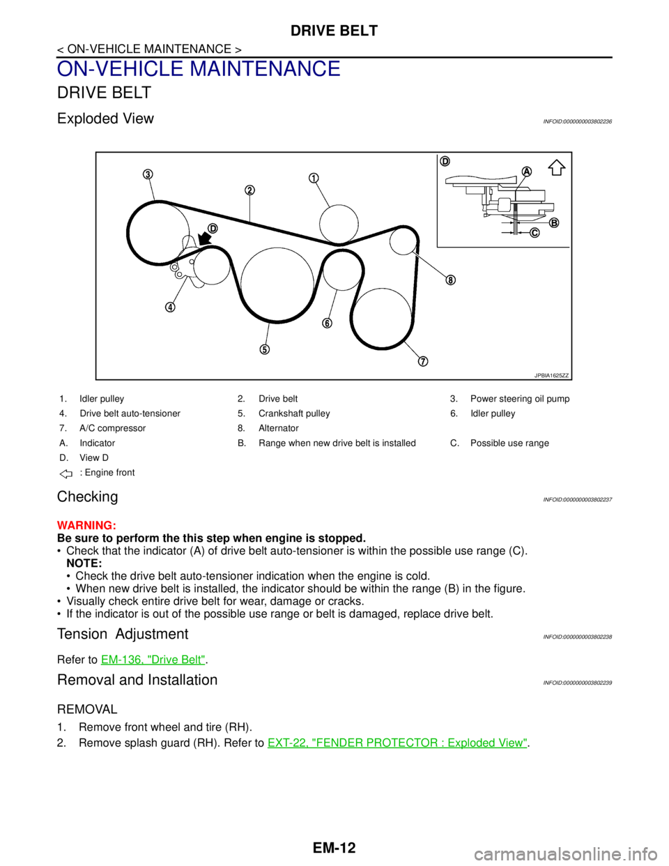
WARNING:
Be sure to perform the this step when engine is stopped.
Check that the indicator (A) of drive belt auto-tensioner is within the possible use range (C).
NOTE:
Check the drive belt auto-tensioner indication when the engine is cold.
When new drive belt is installed, the indicator should be within the range (B) in the figure.
Visually check entire drive belt for wear, damage or cracks.
If the indicator is out of the possible use range or belt is damaged, replace drive belt.
Tension AdjustmentINFOID:0000000003802238
Refer to EM-136, "Drive Belt".
Removal and InstallationINFOID:0000000003802239
REMOVAL
1. Remove front wheel and tire (RH).
2. Remove splash guard (RH). Refer to EXT-22, "
FENDER PROTECTOR : Exploded View".
JPBIA1625ZZ
1. Idler pulley 2. Drive belt 3. Power steering oil pump
4. Drive belt auto-tensioner 5. Crankshaft pulley 6. Idler pulley
7. A/C compressor 8. Alternator
A. Indicator B. Range when new drive belt is installed C. Possible use range
D. View D
: Engine front
Page 3201 of 5121
ENGINE MAINTENANCE
MA-13
< ON-VEHICLE MAINTENANCE >
C
D
E
F
G
H
I
J
K
L
MB
MAN
OA
ENGINE MAINTENANCE
DRIVE BELT
DRIVE BELT : Exploded ViewINFOID:0000000003862446
DRIVE BELT : CheckingINFOID:0000000003862447
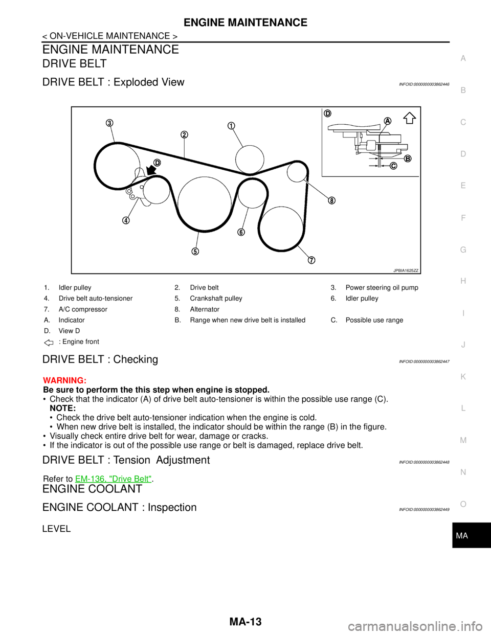
WARNING:
Be sure to perform the this step when engine is stopped.
Check that the indicator (A) of drive belt auto-tensioner is within the possible use range (C).
NOTE:
Check the drive belt auto-tensioner indication when the engine is cold.
When new drive belt is installed, the indicator should be within the range (B) in the figure.
Visually check entire drive belt for wear, damage or cracks.
If the indicator is out of the possible use range or belt is damaged, replace drive belt.
DRIVE BELT : Tension AdjustmentINFOID:0000000003862448
Refer to EM-136, "Drive Belt".
ENGINE COOLANT
ENGINE COOLANT : InspectionINFOID:0000000003862449
LEVEL
JPBIA1625ZZ
1. Idler pulley 2. Drive belt 3. Power steering oil pump
4. Drive belt auto-tensioner 5. Crankshaft pulley 6. Idler pulley
7. A/C compressor 8. Alternator
A. Indicator B. Range when new drive belt is installed C. Possible use range
D. View D
: Engine front