2008 NISSAN TEANA differential
[x] Cancel search: differentialPage 899 of 5121

NOISE, VIBRATION AND HARSHNESS (NVH) TROUBLESHOOTING
BR-3
< SYMPTOM DIAGNOSIS >
C
D
E
G
H
I
J
K
L
MA
B
BR
N
O
P
SYMPTOM DIAGNOSIS
NOISE, VIBRATION AND HARSHNESS (NVH) TROUBLESHOOTING
NVH Troubleshooting ChartINFOID:0000000003811166
Use the chart below to find the cause of the symptom. If necessary, repair or replace these parts.
×: ApplicableReference page
BR-13
, BR-15
BR-13
, BR-15
BR-34
, BR-40
BR-13
, BR-15
BR-13
, BR-15
BR-13
, BR-15
BR-13
, BR-15
BR-13
, BR-15
BR-13
, BR-15
BR-13
, BR-15
NVH in DLN section
NHV in DLN section
NVH in FAX, RAX, FSU and RSU section
NVH in WT section
NVH in WT section
NVH in FAX section
NVH in ST section
Possible cause and
SUSPECTED PARTS
Pads - damaged
Pads - uneven wear
Shims damaged
Rotor imbalance
Rotor damage
Rotor runout
Rotor deformation
Rotor deflection
Rotor rust
Rotor thickness variation
PROPELLER SHAFT
DIFFERENTIAL
AXLE AND SUSPENSION
TIRE
ROAD WHEEL
DRIVE SHAFT
STEERING
Symptom BRAKENoise××× ×× ×××
××
Shake×××××
××
Shimmy, Judder××××××× ××× ×
Page 2010 of 5121
SERVICE DATA AND SPECIFICATIONS (SDS)
EM-135
< SERVICE DATA AND SPECIFICATIONS (SDS)
C
D
E
F
G
H
I
J
K
L
MA
EM
N
P O
SERVICE DATA AND SPECIFICATIONS (SDS)
SERVICE DATA AND SPECIFICATIONS (SDS)
General SpecificationINFOID:0000000003802300
GENERAL SPECIFICATIONS
EngineVQ25DE VQ35DE
Cylinder arrangementV- 6
Displacement cm
3 (cu in)2,495 (152.24) 3,498 (213.45)
Bore and stroke mm (in)85.0 x 73.3
(3.346 x 2.886)95.5 x 81.4
(3.760 x 3.205)
Valve arrangementDOHC
Firing order1-2-3-4-5-6
Number of piston ringsCompression 2
Oil 1
Number of main bearings4
Compression ratio9.8 10.3
Compression pressure
kPa (bar, kg/cm
2, psi)/300 rpmStandard 1,275 (12.8, 13.0, 185)
Minimum 981 (9.8, 10.0, 142)
Differential limit between cylinders 98 (1.0, 1.0, 14)
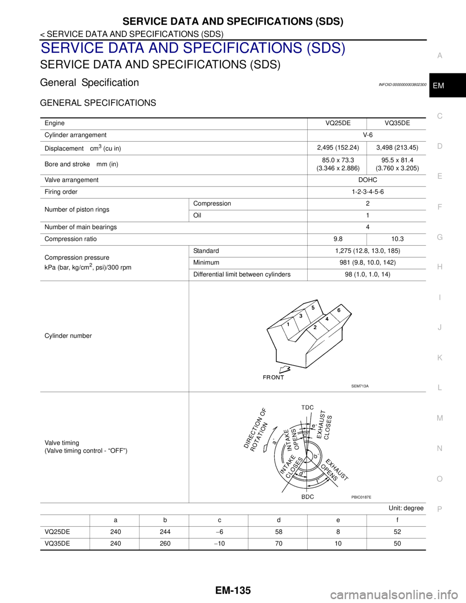
Cylinder number
Valve timing
(Valve timing control - “OFF”)
Unit: degree
ab c d e f
VQ25DE 240 244−658852
VQ35DE 240 260−10 70 10 50
SEM713A
PBIC0187E
Page 2446 of 5121
FAX-18
< ON-VEHICLE REPAIR >
FRONT DRIVE SHAFT
LEFT SIDE
LEFT SIDE : Removal and InstallationINFOID:0000000003811084
REMOVAL
1. Remove tires.
2. Remove wheel sensor and sensor harness. Refer to BRC-57, "
FRONT WHEEL SENSOR : Exploded
View" (without VDC), BRC-151, "FRONT WHEEL SENSOR : Exploded View" (with VDC).
3. Remove lock plate of brake hose from strut assembly. Refer to BR-19, "
FRONT : Exploded View".
4. Remove caliper assembly. Hang caliper assembly not to interfere with work. Refer to BR-34, "
BRAKE
CALIPER ASSEMBLY : Exploded View".
5. Remove disc rotor. Refer to BR-35, "
BRAKE CALIPER ASSEMBLY : Removal and Installation".
6. Remove cotter pin, and then loosen wheel hub lock nut. Refer to FA X - 8 , "
Exploded View".
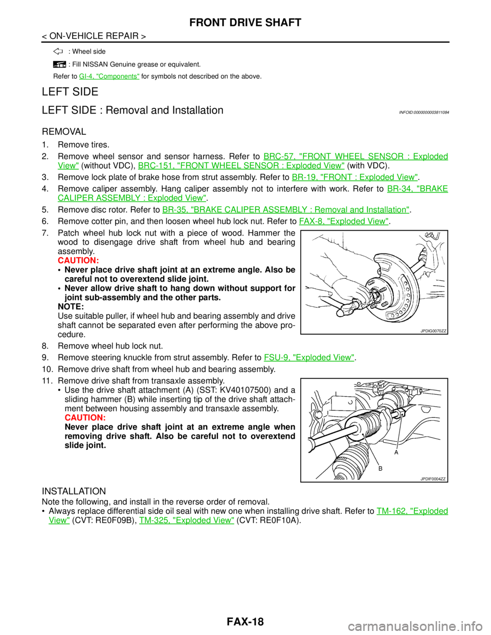
7. Patch wheel hub lock nut with a piece of wood. Hammer the
wood to disengage drive shaft from wheel hub and bearing
assembly.
CAUTION:
Never place drive shaft joint at an extreme angle. Also be
careful not to overextend slide joint.
Never allow drive shaft to hang down without support for
joint sub-assembly and the other parts.
NOTE:
Use suitable puller, if wheel hub and bearing assembly and drive
shaft cannot be separated even after performing the above pro-
cedure.
8. Remove wheel hub lock nut.
9. Remove steering knuckle from strut assembly. Refer to FSU-9, "
Exploded View".
10. Remove drive shaft from wheel hub and bearing assembly.
11. Remove drive shaft from transaxle assembly.
Use the drive shaft attachment (A) (SST: KV40107500) and a
sliding hammer (B) while inserting tip of the drive shaft attach-
ment between housing assembly and transaxle assembly.
CAUTION:
Never place drive shaft joint at an extreme angle when
removing drive shaft. Also be careful not to overextend
slide joint.
INSTALLATION
Note the following, and install in the reverse order of removal.
Always replace differential side oil seal with new one when installing drive shaft. Refer to TM-162, "
Exploded
View" (CVT: RE0F09B), TM-325, "Exploded View" (CVT: RE0F10A).
: Wheel side
: Fill NISSAN Genuine grease or equivalent.
Refer to GI-4, "
Components" for symbols not described on the above.
JPDIG0070ZZ
JPDIF0004ZZ
Page 2448 of 5121
FAX-20
< ON-VEHICLE REPAIR >
FRONT DRIVE SHAFT
Always replace differential side oil seal with new one when installing drive shaft. Refer to TM-162, "Exploded
View" (CVT: RE0F09B), TM-325, "Exploded View" (CVT: RE0F10A).
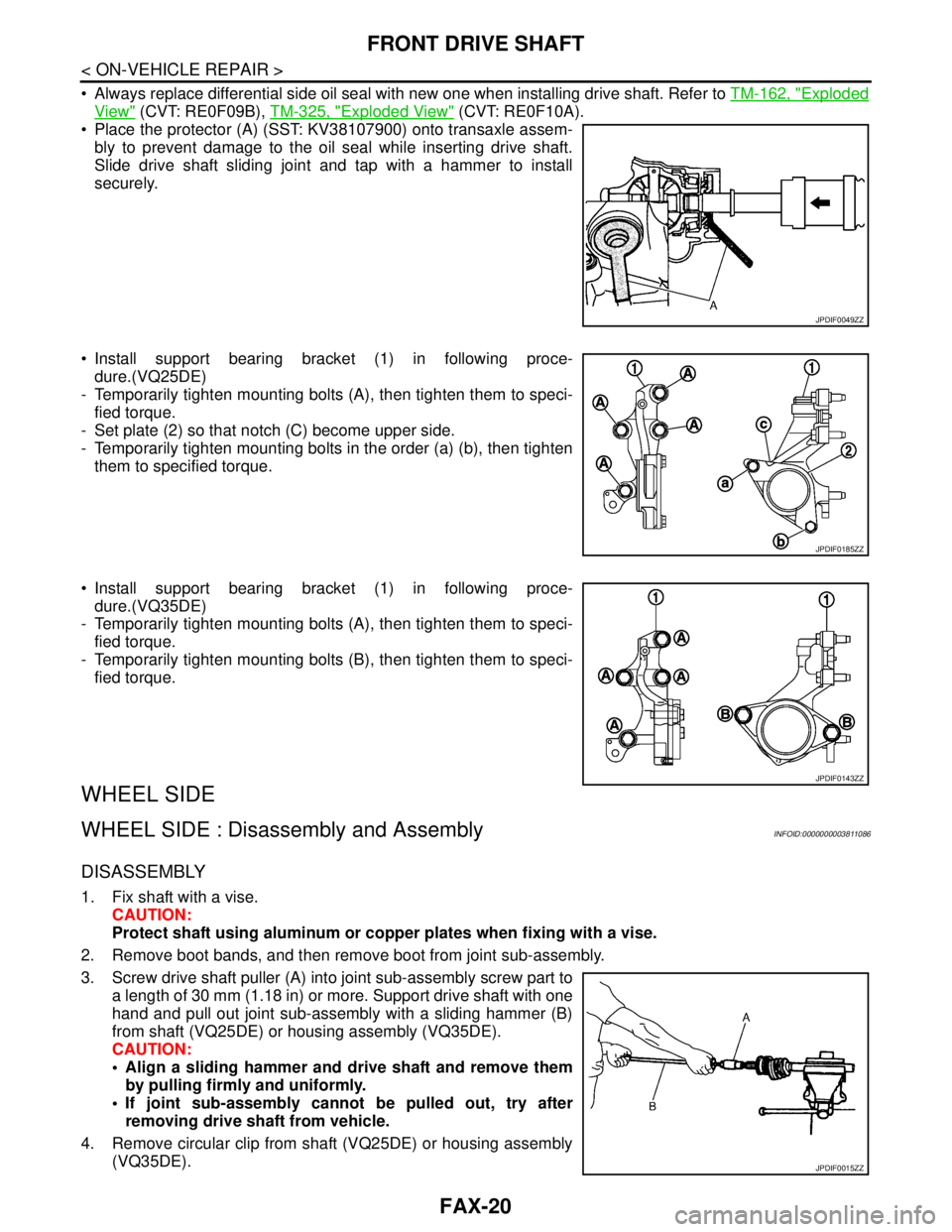
Place the protector (A) (SST: KV38107900) onto transaxle assem-
bly to prevent damage to the oil seal while inserting drive shaft.
Slide drive shaft sliding joint and tap with a hammer to install
securely.
Install support bearing bracket (1) in following proce-
dure.(VQ25DE)
- Temporarily tighten mounting bolts (A), then tighten them to speci-
fied torque.
- Set plate (2) so that notch (C) become upper side.
- Temporarily tighten mounting bolts in the order (a) (b), then tighten
them to specified torque.
Install support bearing bracket (1) in following proce-
dure.(VQ35DE)
- Temporarily tighten mounting bolts (A), then tighten them to speci-
fied torque.
- Temporarily tighten mounting bolts (B), then tighten them to speci-
fied torque.
WHEEL SIDE
WHEEL SIDE : Disassembly and AssemblyINFOID:0000000003811086
DISASSEMBLY
1. Fix shaft with a vise.
CAUTION:
Protect shaft using aluminum or copper plates when fixing with a vise.
2. Remove boot bands, and then remove boot from joint sub-assembly.
3. Screw drive shaft puller (A) into joint sub-assembly screw part to
a length of 30 mm (1.18 in) or more. Support drive shaft with one
hand and pull out joint sub-assembly with a sliding hammer (B)
from shaft (VQ25DE) or housing assembly (VQ35DE).
CAUTION:
Align a sliding hammer and drive shaft and remove them
by pulling firmly and uniformly.
If joint sub-assembly cannot be pulled out, try after
removing drive shaft from vehicle.
4. Remove circular clip from shaft (VQ25DE) or housing assembly
(VQ35DE).
JPDIF0049ZZ
JPDIF0185ZZ
JPDIF0143ZZ
JPDIF0015ZZ
Page 2511 of 5121

GI-18
< HOW TO USE THIS MANUAL >
TERMINOLOGY
Exhaust gas recirculation control-BPT
valveEGRC-BPT valve BPT valve
Exhaust gas recirculation control-solenoid
valveEGRC-solenoid valve EGR control solenoid valve
Exhaust gas recirculation temperature sen-
sor
EGRT sensor Exhaust gas temperature sensor
EGR temperature sensor
Flash electrically erasable programmable
read only memoryFEEPROM ***
Flash erasable programmable read only
memoryFEPROM ***
Flexible fuel sensor FFS ***
Flexible fuel system FF system ***
Fuel pressure regulator *** Pressure regulator
Fuel pressure regulator control solenoid
valve*** PRVR control solenoid valve
Fuel trim FT ***
Heated Oxygen sensor HO2S Exhaust gas sensor
Idle air control system IAC system Idle speed control
Idle air control valve-air regulator IACV-air regulator Air regulator
Idle air control valve-auxiliary air control
valveIACV-AAC valve Auxiliary air control (AAC) valve
Idle air control valve-FICD solenoid valve IACV-FICD solenoid valve FICD solenoid valve
Idle air control valve-idle up control sole-
noid valveIACV-idle up control solenoid valve Idle up control solenoid valve
Idle speed control-FI pot ISC-FI pot FI pot
Idle speed control system ISC system ***
Ignition control IC ***
Ignition control module ICM ***
Indirect fuel injection system IFI system ***
Intake air IA Air
Intake air temperature sensor IAT sensor Air temperature sensor
Knock *** Detonation
Knock sensor KS Detonation sensor
Malfunction indicator lamp MIL Check engine light
Manifold absolute pressure MAP ***
Manifold absolute pressure sensor MAPS ***
Manifold differential pressure MDP ***
Manifold differential pressure sensor MDPS ***
Manifold surface temperature MST ***
Manifold surface temperature sensor MSTS ***
Manifold vacuum zone MVZ ***
Manifold vacuum zone sensor MVZS ***
Mass air flow sensor MAFS Air flow meter
Mixture control solenoid valve MC solenoid valve Air-fuel ratio control solenoid valve
Multiport fuel injection system MFI system Fuel injection controlNEW TERMNEW ACRONYM /
ABBREVIATIONOLD TERM
Page 4392 of 5121
ST-2
< SYMPTOM DIAGNOSIS >
NOISE, VIBRATION AND HARSHNESS (NVH) TROUBLESHOOTING
SYMPTOM DIAGNOSIS
NOISE, VIBRATION AND HARSHNESS (NVH) TROUBLESHOOTING
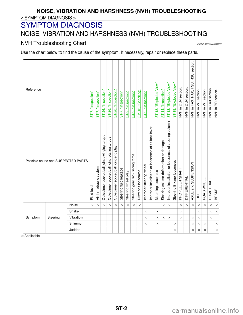
NVH Troubleshooting ChartINFOID:0000000003806305
Use the chart below to find the cause of the symptom. If necessary, repair or replace these parts.
×: ApplicableReference
ST-7, "
Inspection
"
ST-7, "
Inspection
"
ST-26, "
Inspection
"
ST-26, "
Inspection
"
ST-26, "
Inspection
"
ST-7, "
Inspection
"
ST-9, "
Inspection
"
ST-9, "
Inspection
"
EM-12, "
Checking
"
ST-9, "
Inspection
"—
ST-18, "
Exploded View
"
ST-14, "
Inspection
"
ST-13, "
Exploded View
"
ST-18, "
Exploded View
"
NVH in DLN section.
NVH in DLN section.
NVH in FAX, RAX, FSU, RSU section.
NVH in WT section.
NVH in WT section.
NVH in FAX section.
NVH in BR section.
Possible cause and SUSPECTED PARTS
Fluid level
Air in hydraulic system
Outer/inner socket ball joint swinging torque
Outer/inner socket ball joint rotating torque
Outer/inner socket ball joint end play
Steering fluid leakage
Steering wheel play
Steering gear rack sliding force
Drive belt looseness
Improper steering wheel
Improper installation or looseness of tilt lock lever
Mounting looseness
Steering column deformation or damage
Improper installation or looseness of steering column
Steering linkage looseness
PROPELLER SHAFT
DIFFERENTIAL
AXLE and SUSPENSION
TIRE
ROAD WHEEL
DRIVE SHAFT
BRAKE
Symptom SteeringNoise××××××××× ×× ×××××××
Shake× × × ×××××
Vibration××××××××
Shimmy×× × ××××
Judder××××××
Page 4477 of 5121

TM-4
ROAD TEST .....................................................148
Description .............................................................148
Check before Engine Is Started .............................148
Check at Idle ..........................................................149
Cruise Test ............................................................150
CVT POSITION ................................................152
Inspection and Adjustment ....................................152
ON-VEHICLE REPAIR ...............................153
TRANSMISSION CONTROL MODULE ..........153
Exploded View .......................................................153
Removal and Installation .......................................153
Adjustment .............................................................154
CONTROL DEVICE .........................................155
Exploded View .......................................................155
Removal and Installation .......................................155
Inspection and Adjustment ....................................156
CONTROL CABLE ..........................................157
Exploded View .......................................................157
Removal and Installation .......................................157
Inspection and Adjustment ....................................158
OIL PAN ...........................................................159
Exploded View .......................................................159
Removal and Installation .......................................159
Inspection ..............................................................160
SECONDARY SPEED SENSOR .....................161
Exploded View .......................................................161
Removal and Installation .......................................161
Inspection ..............................................................161
DIFFERENTIAL SIDE OIL SEAL ....................162
Exploded View .......................................................162
Removal and Installation .......................................162
Inspection ..............................................................163
AIR BREATHER HOSE ...................................164
Exploded View .......................................................164
Removal and Installation .......................................164
FLUID COOLER SYSTEM ...............................165
Exploded View .......................................................165
Removal and Installation .......................................165
Inspection ..............................................................167
REMOVAL AND INSTALLATION ..............168
TRANSAXLE ASSEMBLY ..............................168
Exploded View .......................................................168
Removal and Installation .......................................168
Inspection ..............................................................170
DISASSEMBLY AND ASSEMBLY ............172
TORQUE CONVERTER ..................................172
Exploded View .......................................................172
Disassembly ..........................................................172
Assembly ..............................................................172
Inspection ..............................................................173
SERVICE DATA AND SPECIFICATIONS
(SDS) .........................................................
174
SERVICE DATA AND SPECIFICATIONS
(SDS) ................................................................
174
General Specification ............................................174
Vehicle Speed When Shifting Gears .....................174
Stall Speed ............................................................174
Line Pressure ........................................................174
Solenoid Valves ....................................................175
CVT Fluid Temperature Sensor ............................175
Primary Speed Sensor ..........................................175
Secondary Speed Sensor .....................................175
Step Motor ............................................................175
Torque Converter ..................................................175
CVT: RE0F10A
BASIC INSPECTION .................................
176
DIAGNOSIS AND REPAIR WORK FLOW .......176
Work Flow .............................................................176
Diagnostic Work Sheet .........................................177
INSPECTION AND ADJUSTMENT ..................179
ADDITIONAL SERVICE WHEN REPLACING
CONTROL UNIT ......................................................
179
ADDITIONAL SERVICE WHEN REPLACING
CONTROL UNIT : Service After Replacing TCM
and Transaxle Assembly .......................................
179
FUNCTION DIAGNOSIS ...........................181
CVT SYSTEM ...................................................181
System Diagram ...................................................181
Component Parts Location ...................................182
MECHANICAL SYSTEM ..................................183
Cross-Sectional View ............................................183
System Diagram ...................................................184
System Description ...............................................184
Component Parts Location ...................................185
Component Description ........................................186
HYDRAULIC CONTROL SYSTEM ..................187
System Diagram ...................................................187
System Description ...............................................187
Component Parts Location ...................................188
Component Description ........................................189
CONTROL SYSTEM .........................................190
System Diagram ...................................................190
System Description ...............................................190
Component Parts Location ...................................192
Component Description ........................................193
LOCK-UP AND SELECT CONTROL SYSTEM
..
194
Page 4480 of 5121
TM-7
C
E
F
G
H
I
J
K
L
MA
B
TM
N
O
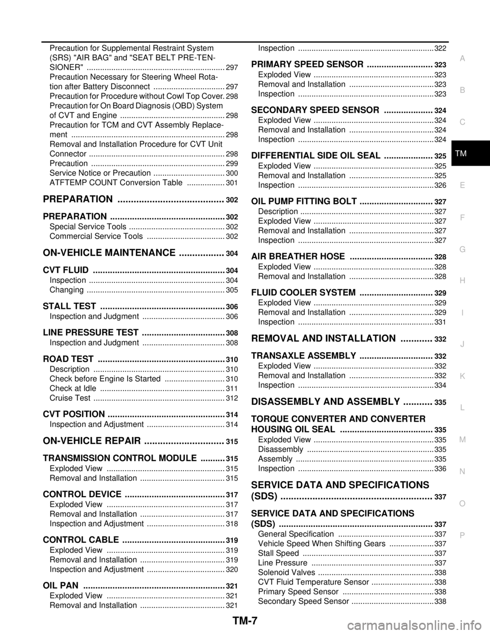
P Precaution for Supplemental Restraint System
(SRS) "AIR BAG" and "SEAT BELT PRE-TEN-
SIONER" ...............................................................
297
Precaution Necessary for Steering Wheel Rota-
tion after Battery Disconnect .................................
297
Precaution for Procedure without Cowl Top Cover ..298
Precaution for On Board Diagnosis (OBD) System
of CVT and Engine ................................................
298
Precaution for TCM and CVT Assembly Replace-
ment ......................................................................
298
Removal and Installation Procedure for CVT Unit
Connector ..............................................................
298
Precaution .............................................................299
Service Notice or Precaution .................................300
ATFTEMP COUNT Conversion Table ..................301
PREPARATION .........................................302
PREPARATION ................................................302
Special Service Tools ............................................302
Commercial Service Tools ....................................302
ON-VEHICLE MAINTENANCE ..................304
CVT FLUID .......................................................304
Inspection ..............................................................304
Changing ...............................................................305
STALL TEST ....................................................306
Inspection and Judgment ......................................306
LINE PRESSURE TEST ...................................308
Inspection and Judgment ......................................308
ROAD TEST .....................................................310
Description ............................................................310
Check before Engine Is Started ............................310
Check at Idle .........................................................311
Cruise Test ............................................................312
CVT POSITION .................................................314
Inspection and Adjustment ....................................314
ON-VEHICLE REPAIR ...............................315
TRANSMISSION CONTROL MODULE ...........315
Exploded View ......................................................315
Removal and Installation .......................................315
CONTROL DEVICE ..........................................317
Exploded View ......................................................317
Removal and Installation .......................................317
Inspection and Adjustment ....................................318
CONTROL CABLE ...........................................319
Exploded View ......................................................319
Removal and Installation .......................................319
Inspection and Adjustment ....................................320
OIL PAN ...........................................................321
Exploded View ......................................................321
Removal and Installation .......................................321
Inspection ..............................................................322
PRIMARY SPEED SENSOR ...........................323
Exploded View .......................................................323
Removal and Installation .......................................323
Inspection ..............................................................323
SECONDARY SPEED SENSOR ....................324
Exploded View .......................................................324
Removal and Installation .......................................324
Inspection ..............................................................324
DIFFERENTIAL SIDE OIL SEAL ....................325
Exploded View .......................................................325
Removal and Installation .......................................325
Inspection ..............................................................326
OIL PUMP FITTING BOLT ..............................327
Description .............................................................327
Exploded View .......................................................327
Removal and Installation .......................................327
Inspection ..............................................................327
AIR BREATHER HOSE ..................................328
Exploded View .......................................................328
Removal and Installation .......................................328
FLUID COOLER SYSTEM ..............................329
Exploded View .......................................................329
Removal and Installation .......................................329
Inspection ..............................................................331
REMOVAL AND INSTALLATION .............332
TRANSAXLE ASSEMBLY ..............................332
Exploded View .......................................................332
Removal and Installation .......................................332
Inspection ..............................................................334
DISASSEMBLY AND ASSEMBLY ............335
TORQUE CONVERTER AND CONVERTER
HOUSING OIL SEAL ......................................
335
Exploded View .......................................................335
Disassembly ..........................................................335
Assembly ...............................................................335
Inspection ..............................................................336
SERVICE DATA AND SPECIFICATIONS
(SDS) ..........................................................
337
SERVICE DATA AND SPECIFICATIONS
(SDS) ...............................................................
337
General Specification ............................................337
Vehicle Speed When Shifting Gears .....................337
Stall Speed ............................................................337
Line Pressure ........................................................337
Solenoid Valves .....................................................338
CVT Fluid Temperature Sensor .............................338
Primary Speed Sensor ..........................................338
Secondary Speed Sensor ......................................338