2008 NISSAN TEANA oil reset
[x] Cancel search: oil resetPage 1580 of 5121
![NISSAN TEANA 2008 Service Manual ON BOARD DIAGNOSTIC (OBD) SYSTEM
EC-119
< FUNCTION DIAGNOSIS >[VQ25DE, VQ35DE]
C
D
E
F
G
H
I
J
K
L
MA
EC
N
P O
HO2S2 HTR (B1)
ON/OFF Indicates [ON/OFF] condition of heated oxygen
sensor 2 heater det NISSAN TEANA 2008 Service Manual ON BOARD DIAGNOSTIC (OBD) SYSTEM
EC-119
< FUNCTION DIAGNOSIS >[VQ25DE, VQ35DE]
C
D
E
F
G
H
I
J
K
L
MA
EC
N
P O
HO2S2 HTR (B1)
ON/OFF Indicates [ON/OFF] condition of heated oxygen
sensor 2 heater det](/manual-img/5/57391/w960_57391-1579.png)
ON BOARD DIAGNOSTIC (OBD) SYSTEM
EC-119
< FUNCTION DIAGNOSIS >[VQ25DE, VQ35DE]
C
D
E
F
G
H
I
J
K
L
MA
EC
N
P O
HO2S2 HTR (B1)
ON/OFF Indicates [ON/OFF] condition of heated oxygen
sensor 2 heater determined by ECM according to
the input signals. HO2S2 HTR (B2)
I/P PULLY SPD rpm Indicates the engine speed computed from the
turbine revolution sensor signal.
VEHICLE SPEED km/h or mph The vehicle speed computed from the vehicle
speed signal sent from TCM is displayed.
IDL A/V LEARN YET/CMPLT Displays the condition of idle air volume learning
YET: Idle Air Volume Learning has not been per-
formed yet.
CMPLT: Idle Air Volume Learning has already
been performed successfully.
ENG OIL TEMP°C or °F The engine oil temperature (determined by the
signal voltage of the engine oil temperature sen-
sor) is displayed.
TRVL AFTER MIL km or mile Distance traveled while MI is activated.
A/F S1 HTR(B1)
% Air fuel ratio (A/F) sensor 1 heater control value
computed by ECM according to the input signals.
The current flow to the heater becomes larger as
the value increases. A/F S1 HTR(B2)
AC PRESS SEN V The signal voltage from the refrigerant pressure
sensor is displayed.
VHCL SPEED SE km/h or mph The vehicle speed computed from the vehicle
speed signal sent from combination meter is dis-
played.
SET VHCL SPD km/h or mph The preset vehicle speed is displayed.
MAIN SW ON/OFF Indicates [ON/OFF] condition from MAIN switch
signal.
CANCEL SW ON/OFF Indicates [ON/OFF] condition from CANCEL
switch signal.
RESUME/ACC SW ON/OFF Indicates [ON/OFF] condition from RESUME/AC-
CELERATE switch signal.
SET SW ON/OFF Indicates [ON/OFF] condition from SET/COAST
switch signal.
BRAKE SW1 ON/OFF Indicates [ON/OFF] condition from ASCD brake
switch signal or ASCD clutch switch.
BRAKE SW2 ON/OFF Indicates [ON/OFF] condition of stop lamp switch
signal.
VHCL SPD CUT NON/CUT Indicates the vehicle cruise condition.
NON: Vehicle speed is maintained at the ASCD
set speed.
CUT: Vehicle speed decreased to excessively
low compared with the ASCD set speed, and
ASCD operation is cut off.
LO SPEED CUT NON/CUT Indicates the vehicle cruise condition.
NON: Vehicle speed is maintained at the ASCD
set speed.
CUT: Vehicle speed decreased to excessively
low, and ASCD operation is cut off.
AT O D M O N I TO R O N / O F F Indicates [ON/OFF] condition of CVT O/D ac-
cording to the input signal from the TCM.
AT OD CANCEL ON/OFF Indicates [ON/OFF] condition of CVT O/D cancel
request signal.
CRUISE LAMP ON/OFF Indicates [ON/OFF] condition of CRUISE lamp
determined by the ECM according to the input
signals. Monitored item Unit Description Remarks
Page 1821 of 5121
![NISSAN TEANA 2008 Service Manual EC-360
< ECU DIAGNOSIS >[VQ25DE, VQ35DE]
ECM
IDL A/V LEARN Engine: RunningIdle air volume learning has not been per-
formed yet.YET
Idle air volume learning has already been
performed successfully. NISSAN TEANA 2008 Service Manual EC-360
< ECU DIAGNOSIS >[VQ25DE, VQ35DE]
ECM
IDL A/V LEARN Engine: RunningIdle air volume learning has not been per-
formed yet.YET
Idle air volume learning has already been
performed successfully.](/manual-img/5/57391/w960_57391-1820.png)
EC-360
< ECU DIAGNOSIS >[VQ25DE, VQ35DE]
ECM
IDL A/V LEARN Engine: RunningIdle air volume learning has not been per-
formed yet.YET
Idle air volume learning has already been
performed successfully.CMPLT
ENG OIL TEMP Engine: After warming up More than 70°C (158°F)
TRVL AFTER MIL Ignition switch: ONVehicle has traveled after MI has illumi-
nated.0 - 65,535 km
(0 - 40,723 miles)
A/F S1 HTR (B1) Engine: After warming up, idle the engine
(More than 140 seconds after starting engine)4 - 100%
A/F S1 HTR (B2) Engine: After warming up, idle the engine
(More than 140 seconds after starting engine)4 - 100%
AC PRESS SEN Engine: Idle
Both A/C switch and blower fan switch: ON (Compressor operates)1.0 - 4.0 V
VHCL SPEED SE Turn drive wheels and compare CONSULT-III value with the speedometer in-
dication.Almost the same speed as
the speedometer indication
SET VHCL SPD Engine: Running ASCD: OperatingThe preset vehicle speed is
displayed
MAIN SW Ignition switch: ONMAIN switch: Pressed ON
MAIN switch: Released OFF
CANCEL SW Ignition switch: ONCANCEL switch: Pressed ON
CANCEL switch: Released OFF
RESUME/ACC SW Ignition switch: ONRESUME/ACCELERATE switch:
PressedON
RESUME/ACCELERATE switch: Re-
leasedOFF
SET SW Ignition switch: ONSET/COAST switch: Pressed ON
SET/COAST switch: Released OFF
BRAKE SW1
(ASCD brake switch) Ignition switch: ONBrake pedal: Fully released ON
Brake pedal: Slightly depressed OFF
BRAKE SW2
(Stop lamp switch) Ignition switch: ONBrake pedal: Fully released OFF
Brake pedal: Slightly depressed ON
VHCL SPD CUT Ignition switch: ON NON
LO SPEED CUT Ignition switch: ON NON
AT OD MONITOR Ignition switch: ON OFF
AT OD CANCEL Ignition switch: ON OFF
CRUISE LAMP Ignition switch: ONMAIN switch: Pressed at the 1st time →
at the 2nd timeON → OFF
SET LAMP MAIN switch: ON
When vehicle speed is between
40 km/h (25 MPH) and 144 km/h
(89 MPH)ASCD: Operating ON
ASCD: Not operating OFF
ALT DUTY Engine: Idle 0 - 80%
A/F ADJ-B1 Engine: Running−0.330 - 0.330
A/F ADJ-B2 Engine: Running−0.330 - 0.330
BAT CUR SEN Engine speed: Idle
Battery: Fully charged*
2
Selector lever: P or N
Air conditioner switch: OFF
No loadApprox. 2,600 - 3,500 mV Monitor Item Condition Values/Status
Page 3261 of 5121
MWI
METER SYSTEM
MWI-7
< FUNCTION DIAGNOSIS >
C
D
E
F
G
H
I
J
K
L
MB A
O
P
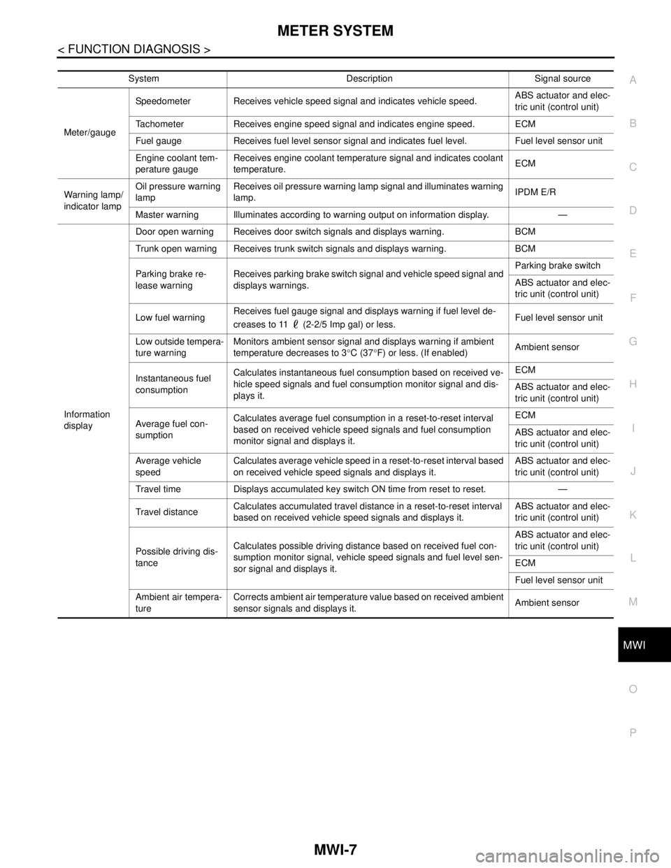
System Description Signal source
Meter/gaugeSpeedometer Receives vehicle speed signal and indicates vehicle speed.ABS actuator and elec-
tric unit (control unit)
Tachometer Receives engine speed signal and indicates engine speed. ECM
Fuel gauge Receives fuel level sensor signal and indicates fuel level. Fuel level sensor unit
Engine coolant tem-
perature gaugeReceives engine coolant temperature signal and indicates coolant
temperature.ECM
Warning lamp/
indicator lampOil pressure warning
lampReceives oil pressure warning lamp signal and illuminates warning
lamp.IPDM E/R
Master warning Illuminates according to warning output on information display. —
Information
displayDoor open warning Receives door switch signals and displays warning. BCM
Trunk open warning Receives trunk switch signals and displays warning. BCM
Parking brake re-
lease warningReceives parking brake switch signal and vehicle speed signal and
displays warnings.Parking brake switch
ABS actuator and elec-
tric unit (control unit)
Low fuel warningReceives fuel gauge signal and displays warning if fuel level de-
creases to 11 (2-2/5 Imp gal) or less.Fuel level sensor unit
Low outside tempera-
ture warningMonitors ambient sensor signal and displays warning if ambient
temperature decreases to 3°C (37°F) or less. (If enabled)Ambient sensor
Instantaneous fuel
consumptionCalculates instantaneous fuel consumption based on received ve-
hicle speed signals and fuel consumption monitor signal and dis-
plays it.ECM
ABS actuator and elec-
tric unit (control unit)
Average fuel con-
sumptionCalculates average fuel consumption in a reset-to-reset interval
based on received vehicle speed signals and fuel consumption
monitor signal and displays it.ECM
ABS actuator and elec-
tric unit (control unit)
Average vehicle
speedCalculates average vehicle speed in a reset-to-reset interval based
on received vehicle speed signals and displays it.ABS actuator and elec-
tric unit (control unit)
Travel time Displays accumulated key switch ON time from reset to reset. —
Travel distanceCalculates accumulated travel distance in a reset-to-reset interval
based on received vehicle speed signals and displays it.ABS actuator and elec-
tric unit (control unit)
Possible driving dis-
tanceCalculates possible driving distance based on received fuel con-
sumption monitor signal, vehicle speed signals and fuel level sen-
sor signal and displays it.ABS actuator and elec-
tric unit (control unit)
ECM
Fuel level sensor unit
Ambient air tempera-
tureCorrects ambient air temperature value based on received ambient
sensor signals and displays it.Ambient sensor
Page 3321 of 5121
MWI
COMBINATION METER
MWI-67
< ECU DIAGNOSIS >
C
D
E
F
G
H
I
J
K
L
MB A
O
P
DTC IndexINFOID:0000000003792591
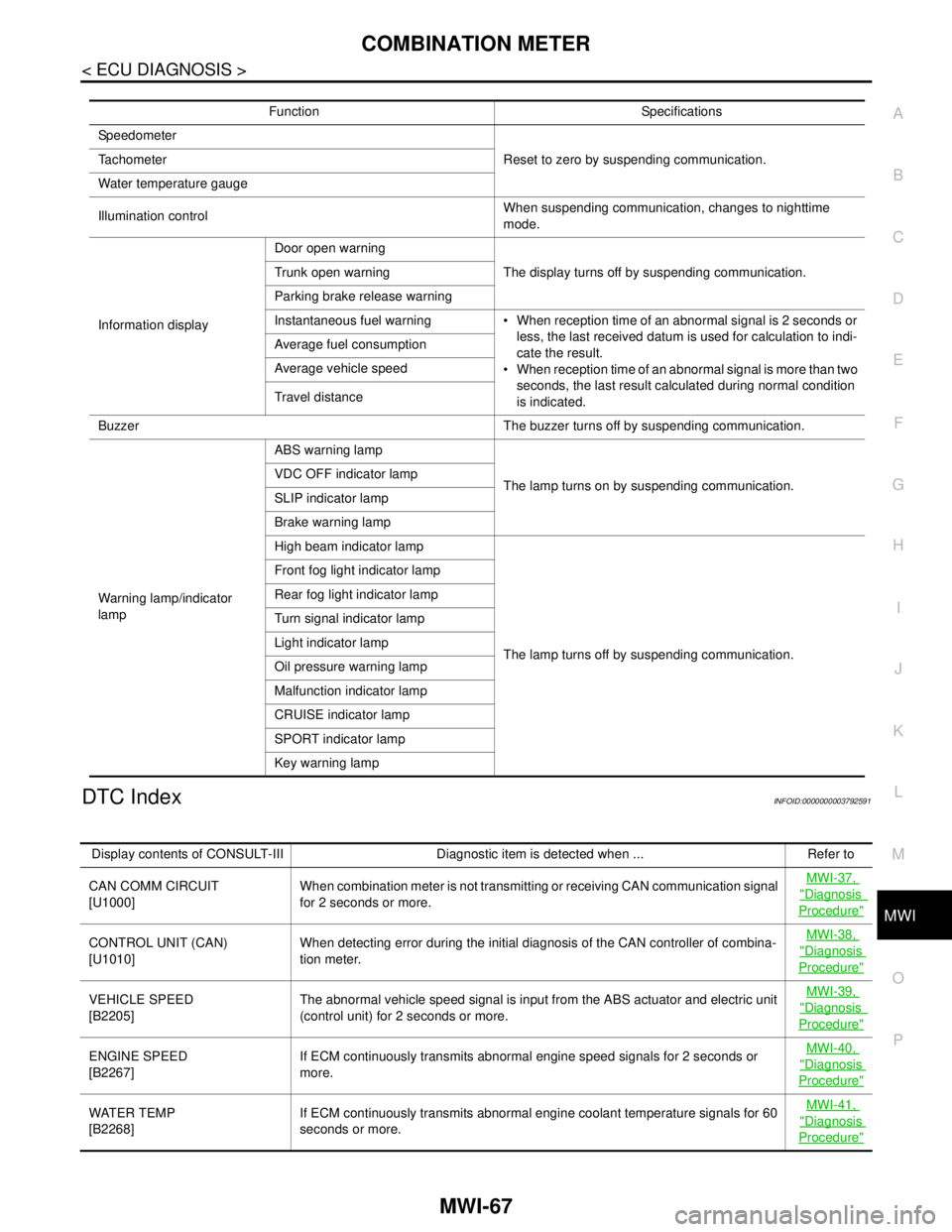
Function Specifications
Speedometer
Reset to zero by suspending communication. Tachometer
Water temperature gauge
Illumination controlWhen suspending communication, changes to nighttime
mode.
Information displayDoor open warning
The display turns off by suspending communication. Trunk open warning
Parking brake release warning
Instantaneous fuel warning When reception time of an abnormal signal is 2 seconds or
less, the last received datum is used for calculation to indi-
cate the result.
When reception time of an abnormal signal is more than two
seconds, the last result calculated during normal condition
is indicated. Average fuel consumption
Average vehicle speed
Travel distance
Buzzer The buzzer turns off by suspending communication.
Warning lamp/indicator
lampABS warning lamp
The lamp turns on by suspending communication. VDC OFF indicator lamp
SLIP indicator lamp
Brake warning lamp
High beam indicator lamp
The lamp turns off by suspending communication. Front fog light indicator lamp
Rear fog light indicator lamp
Turn signal indicator lamp
Light indicator lamp
Oil pressure warning lamp
Malfunction indicator lamp
CRUISE indicator lamp
SPORT indicator lamp
Key warning lamp
Display contents of CONSULT-III Diagnostic item is detected when ... Refer to
CAN COMM CIRCUIT
[U1000]When combination meter is not transmitting or receiving CAN communication signal
for 2 seconds or more.MWI-37,
"Diagnosis
Procedure"
CONTROL UNIT (CAN)
[U1010]When detecting error during the initial diagnosis of the CAN controller of combina-
tion meter.MWI-38, "Diagnosis
Procedure"
VEHICLE SPEED
[B2205]The abnormal vehicle speed signal is input from the ABS actuator and electric unit
(control unit) for 2 seconds or more.MWI-39, "Diagnosis
Procedure"
ENGINE SPEED
[B2267]If ECM continuously transmits abnormal engine speed signals for 2 seconds or
more.MWI-40, "Diagnosis
Procedure"
WATER TEMP
[B2268]If ECM continuously transmits abnormal engine coolant temperature signals for 60
seconds or more.MWI-41, "Diagnosis
Procedure"
Page 4224 of 5121
SR-10
< ON-VEHICLE REPAIR >
SPIRAL CABLE
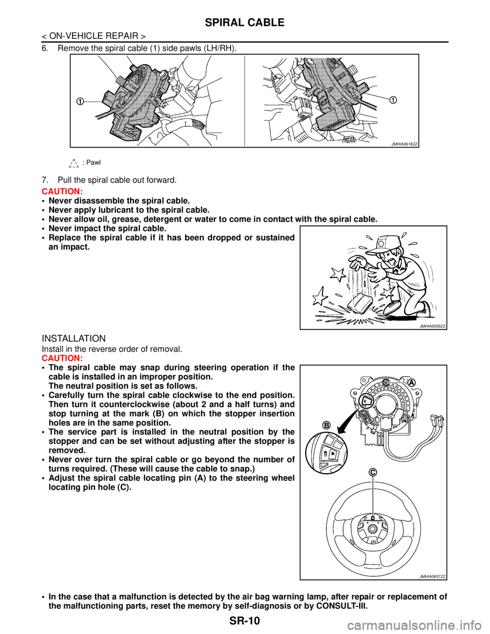
6. Remove the spiral cable (1) side pawls (LH/RH).
7. Pull the spiral cable out forward.
CAUTION:
Never disassemble the spiral cable.
Never apply lubricant to the spiral cable.
Never allow oil, grease, detergent or water to come in contact with the spiral cable.
Never impact the spiral cable.
Replace the spiral cable if it has been dropped or sustained
an impact.
INSTALLATION
Install in the reverse order of removal.
CAUTION:
The spiral cable may snap during steering operation if the
cable is installed in an improper position.
The neutral position is set as follows.
Carefully turn the spiral cable clockwise to the end position.
Then turn it counterclockwise (about 2 and a half turns) and
stop turning at the mark (B) on which the stopper insertion
holes are in the same position.
The service part is installed in the neutral position by the
stopper and can be set without adjusting after the stopper is
removed.
Never over turn the spiral cable or go beyond the number of
turns required. (These will cause the cable to snap.)
Adjust the spiral cable locating pin (A) to the steering wheel
locating pin hole (C).
In the case that a malfunction is detected by the air bag warning lamp, after repair or replacement of
the malfunctioning parts, reset the memory by self-diagnosis or by CONSULT-III.
: Pawl
JMHIA0618ZZ
JMHIA0009ZZ
JMHIA0657ZZ
Page 4227 of 5121
FRONT PASSENGER AIR BAG MODULE
SR-13
< ON-VEHICLE REPAIR >
C
D
E
F
G
I
J
K
L
MA
B
SR
N
O
P
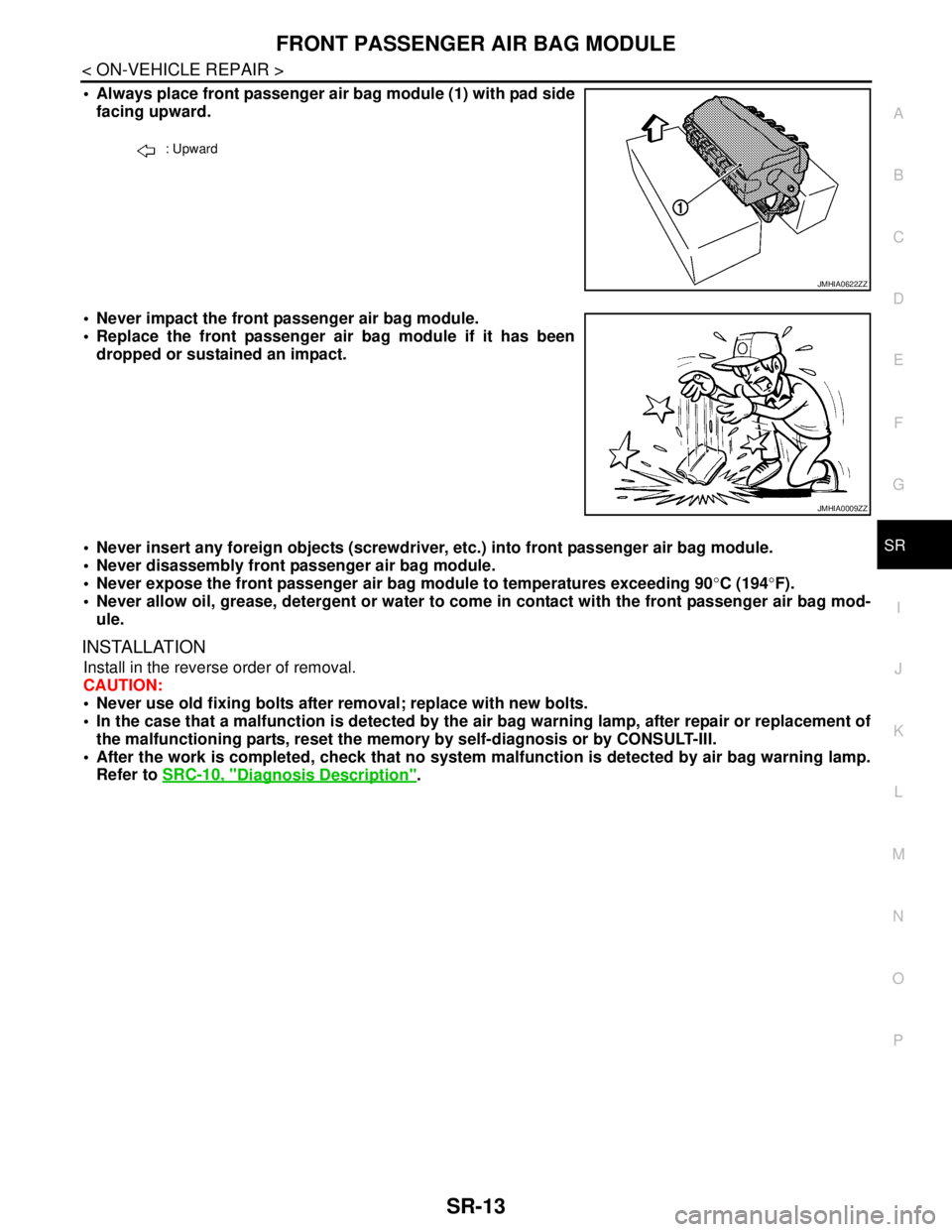
Always place front passenger air bag module (1) with pad side
facing upward.
Never impact the front passenger air bag module.
Replace the front passenger air bag module if it has been
dropped or sustained an impact.
Never insert any foreign objects (screwdriver, etc.) into front passenger air bag module.
Never disassembly front passenger air bag module.
Never expose the front passenger air bag module to temperatures exceeding 90°C (194°F).
Never allow oil, grease, detergent or water to come in contact with the front passenger air bag mod-
ule.
INSTALLATION
Install in the reverse order of removal.
CAUTION:
Never use old fixing bolts after removal; replace with new bolts.
In the case that a malfunction is detected by the air bag warning lamp, after repair or replacement of
the malfunctioning parts, reset the memory by self-diagnosis or by CONSULT-III.
After the work is completed, check that no system malfunction is detected by air bag warning lamp.
Refer to SRC-10, "
Diagnosis Description".
: Upward
JMHIA0622ZZ
JMHIA0009ZZ
Page 4229 of 5121
SIDE CURTAIN AIR BAG MODULE
SR-15
< ON-VEHICLE REPAIR >
C
D
E
F
G
I
J
K
L
MA
B
SR
N
O
P
3. Remove fixing bolts, and then remove side curtain air bag module.
CAUTION:
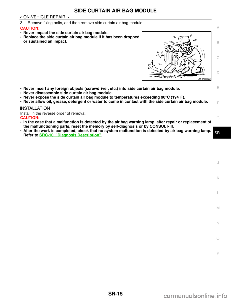
Never impact the side curtain air bag module.
Replace the side curtain air bag module if it has been dropped
or sustained an impact.
Never insert any foreign objects (screwdriver, etc.) into side curtain air bag module.
Never disassemble side curtain air bag module.
Never expose the side curtain air bag module to temperatures exceeding 90°C (194°F).
Never allow oil, grease, detergent or water to come in contact with the side curtain air bag module.
INSTALLATION
Install in the reverse order of removal.
CAUTION:
In the case that a malfunction is detected by the air bag warning lamp, after repair or replacement of
the malfunctioning parts, reset the memory by self-diagnosis or by CONSULT-III.
After the work is completed, check that no system malfunction is detected by air bag warning lamp.
Refer to SRC-10, "
Diagnosis Description".
JMHIA0009ZZ
Page 4231 of 5121
FRONT SIDE AIR BAG MODULE
SR-17
< ON-VEHICLE REPAIR >
C
D
E
F
G
I
J
K
L
MA
B
SR
N
O
P
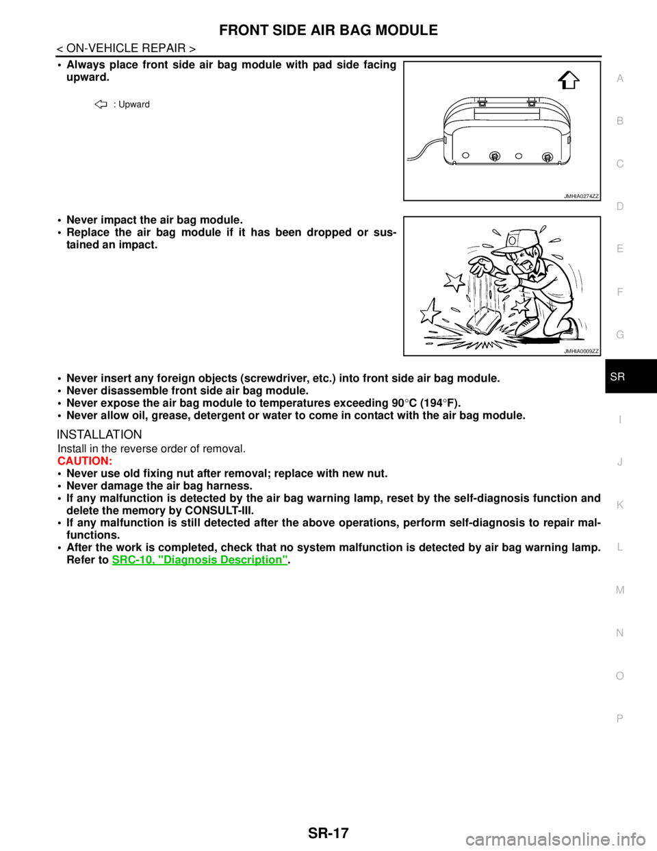
Always place front side air bag module with pad side facing
upward.
Never impact the air bag module.
Replace the air bag module if it has been dropped or sus-
tained an impact.
Never insert any foreign objects (screwdriver, etc.) into front side air bag module.
Never disassemble front side air bag module.
Never expose the air bag module to temperatures exceeding 90°C (194°F).
Never allow oil, grease, detergent or water to come in contact with the air bag module.
INSTALLATION
Install in the reverse order of removal.
CAUTION:
Never use old fixing nut after removal; replace with new nut.
Never damage the air bag harness.
If any malfunction is detected by the air bag warning lamp, reset by the self-diagnosis function and
delete the memory by CONSULT-III.
If any malfunction is still detected after the above operations, perform self-diagnosis to repair mal-
functions.
After the work is completed, check that no system malfunction is detected by air bag warning lamp.
Refer to SRC-10, "
Diagnosis Description".
: Upward
JMHIA0274ZZ
JMHIA0009ZZ