2008 NISSAN TEANA oil pressure
[x] Cancel search: oil pressurePage 829 of 5121

BCS-12
< FUNCTION DIAGNOSIS >
SIGNAL BUFFER SYSTEM
SIGNAL BUFFER SYSTEM
System DiagramINFOID:0000000003809589
System DescriptionINFOID:0000000003809590
OUTLINE
BCM has the signal transmission function that outputs/transmits each input/received signal to each unit.
Signal transmission function list
JPMIA1045GB
Signal name Input Output Description
Ignition switch ON signal
Ignition switch signalPush-button ignition switch
(push switch) IPDM E/R (CAN)
Driver seat control unit (CAN)Inputs the push-button ignition
switch (push switch) signal and
transmits the ignition switch sta-
tus judged with BCM via CAN
communication.
Door switch signal Any door switch Combination meter (CAN)
IPDM E/R (CAN)
Driver seat control unit (CAN)
AV control unit (CAN)Inputs the door switch signal
and transmits it via CAN com-
munication.
Trunk switch signal Trunk room lamp switch Combination meter (CAN)
AV control unit (CAN)Inputs the trunk room lamp
switch signal and transmits the
trunk switch signal via CAN
communication.
Oil pressure switch signal IPDM E/R (CAN) Combination meter (CAN)Transmits the received oil pres-
sure switch signal via CAN
communication.
Stop lamp switch signal Stop lamp switch TCM (CAN)Inputs the stop lamp switch sig-
nal and transmits it via CAN
communication.
Page 849 of 5121

BCS-32
< FUNCTION DIAGNOSIS >
DIAGNOSIS SYSTEM (BCM)
WORK SUPPORT
ACTIVE TEST
SIGNAL BUFFER
SIGNAL BUFFER : CONSULT-III Function (BCM - SIGNAL BUFFER)INFOID:0000000003809611
DATA MONITOR
ACTIVE TEST
CDL LOCK SW Indicates [ON/OFF] condition of lock signal from door lock/unlock switch.
CDL UNLOCK SW Indicates [ON/OFF] condition of unlock signal from door lock/unlock switch.
KEY CYL LK-SWNOTE:
This is displayed even when it is not equipped.
KEY CYL UN-SWNOTE:
This is displayed even when it is not equipped.
KEY CYL SW-TRNOTE:
This is displayed even when it is not equipped.
TR/BD OPEN SW Indicates [ON/OFF] condition of trunk lid opener switch.
TRNK/HAT MNTR Indicates [ON/OFF] condition of trunk room lamp switch.
RKE-LOCK Indicates [ON/OFF] condition of LOCK signal from Intelligent Key.
RKE-UNLOCK Indicates [ON/OFF] condition of UNLOCK signal from Intelligent Key.
RKE-TR/BD Indicates [ON/OFF] condition of TRUNK LID OPEN signal from Intelligent Key. Monitored Item Description
Test Item Description
SECURITY ALARM SET This mode is able to confirm and change security alarm ON-OFF setting.
THEFT ALM TRGThe switch which triggered vehicle security alarm is recorded. This mode is able to confirm and
erase the record of vehicle security alarm. The trigger data can be erased by touching “CLEAR” on
CONSULT-III screen.
Test Item Description
THEFT INDThis test is able to check security indicator lamp operation. The lamp will be turned on when “ON”
on CONSULT-III screen is touched.
HEADLAMP(HI)This test is able to check vehicle security lamp operation. The headlamps will be activated for 0.5
seconds after “ON” on CONSULT-III screen is touched.
FLASHERThis test is able to check vehicle security hazard lamp operation. The hazard lamps will be activat-
ed after “ON” on CONSULT-III screen is touched.
Monitor item [UNIT] Description
PUSH SW
[Off/On]Displays the status of the push-button ignition switch (push switch) judged by BCM.
Te s t i t e mOpera-
tionDescription
OIL PRESSURE SWOff OFF
OnBCM transmits the oil pressure switch signal to the combination meter via CAN communica-
tion, which illuminates the oil pressure warning lamp in the combination meter.
Page 921 of 5121

BRAKE MASTER CYLINDER
BR-25
< ON-VEHICLE REPAIR >
C
D
E
G
H
I
J
K
L
MA
B
BR
N
O
P
BRAKE MASTER CYLINDER
Exploded ViewINFOID:0000000003811194
Removal and InstallationINFOID:0000000003811195
REMOVAL
CAUTION:
Never spill or splash brake fluid on painted surfaces. Brake fluid may seriously damage paint. Wipe it
off immediately and wash with water if it gets on a painted surface.
1. Drain brake fluid. Refer to BR-9, "
Draining".
2. Remove air duct and air cleaner case. Refer to EM-26, "
Exploded View".
3. Separate the brake fluid level switch harness connector and harness clip.
4. Separate the brake tubes from the master cylinder assembly with a flare nut wrench.
CAUTION:
Never scratch the flare nut and the brake tube.
5. Remove the master cylinder assembly.
CAUTION:
Depress the brake pedal several times to release the vacuum pressure from the brake booster.
Then remove the master cylinder assembly.
Never depress the brake pedal after the master cylinder assembly is removed.
The piston of the master cylinder assembly is exposed. Never damage it when removing the
master cylinder.
1. Reservoir cap 2. Oil strainer 3. Reservoir tank
4. Cylinder body 5. Pin 6. O-ring
7. Grommet
: Apply PBC (Poly Butyl Cuprysil) grease or silicone-based grease.
: Apply brake fluid.
Refer to GI-4, "
Components" for symbols not described on the above.
JPFIA0347GB
Page 1120 of 5121

CHG-22
< ON-VEHICLE REPAIR >
ALTERNATOR
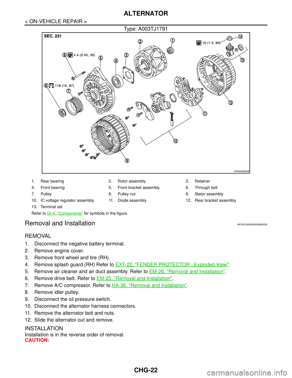
Type: A003TJ1791
Removal and InstallationINFOID:0000000003860539
REMOVAL
1. Disconnect the negative battery terminal.
2. Remove engine cover.
3. Remove front wheel and tire (RH).
4. Remove splash guard (RH) Refer to EXT-22, "
FENDER PROTECTOR : Exploded View".
5. Remove air cleaner and air duct assembly. Refer to EM-26, "
Removal and Installation".
6. Remove drive belt. Refer to EM-25, "
Removal and Installation".
7. Remove A/C compressor. Refer to HA-36, "
Removal and Installation".
8. Remove idler pulley.
9. Disconnect the oil pressure switch.
10. Disconnect the alternator harness connectors.
11. Remove the alternator bolt and nuts.
12. Slide the alternator out and remove.
INSTALLATION
Installation is in the reverse order of removal.
CAUTION:
JPMIA0859GB
1. Rear bearing 2. Rotor assembly 3. Retainer
4. Front bearing 5. Front bracket assembly 6. Through bolt
7. Pulley 8. Pulley nut 9. Stator assembly
10. IC voltage regulator assembly 11. Diode assembly 12. Rear bracket assembly
13. Terminal set
Refer to GI-4, "
Components" for symbols in the figure.
Page 1123 of 5121

CHG
SERVICE DATA AND SPECIFICATIONS (SDS)
CHG-25
< SERVICE DATA AND SPECIFICATIONS (SDS)
C
D
E
F
G
H
I
J
K
L B A
O
P N
SERVICE DATA AND SPECIFICATIONS (SDS)
SERVICE DATA AND SPECIFICATIONS (SDS)
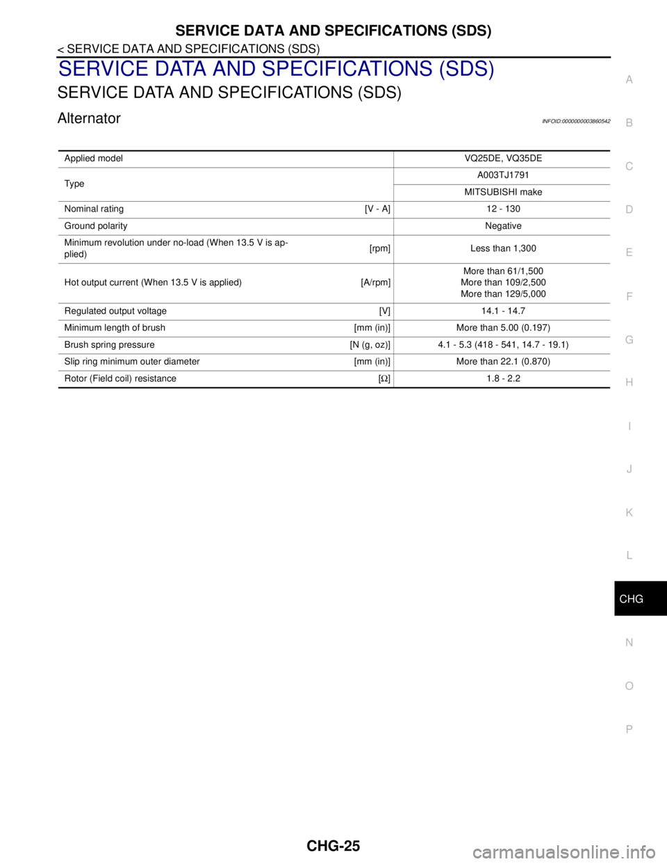
AlternatorINFOID:0000000003860542
Applied modelVQ25DE, VQ35DE
Typ eA003TJ1791
MITSUBISHI make
Nominal rating [V - A] 12 - 130
Ground polarityNegative
Minimum revolution under no-load (When 13.5 V is ap-
plied)[rpm] Less than 1,300
Hot output current (When 13.5 V is applied) [A/rpm]More than 61/1,500
More than 109/2,500
More than 129/5,000
Regulated output voltage [V] 14.1 - 14.7
Minimum length of brush [mm (in)] More than 5.00 (0.197)
Brush spring pressure [N (g, oz)] 4.1 - 5.3 (418 - 541, 14.7 - 19.1)
Slip ring minimum outer diameter [mm (in)] More than 22.1 (0.870)
Rotor (Field coil) resistance [Ω] 1.8 - 2.2
Page 1135 of 5121

CO-12
< ON-VEHICLE MAINTENANCE >
RADIATOR
RADIATOR
RADIATOR CAP
RADIATOR CAP : InspectionINFOID:0000000003793170
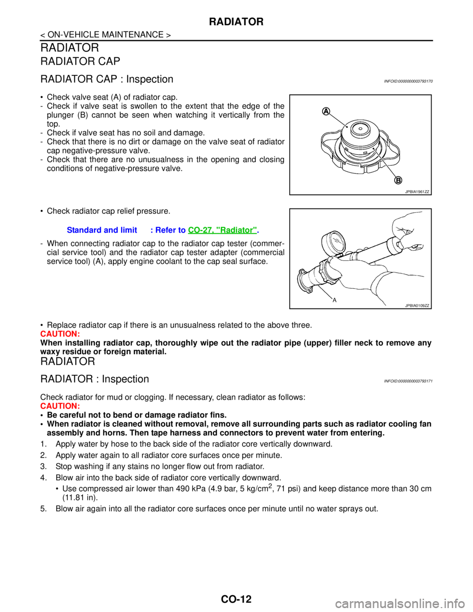
Check valve seat (A) of radiator cap.
- Check if valve seat is swollen to the extent that the edge of the
plunger (B) cannot be seen when watching it vertically from the
top.
- Check if valve seat has no soil and damage.
- Check that there is no dirt or damage on the valve seat of radiator
cap negative-pressure valve.
- Check that there are no unusualness in the opening and closing
conditions of negative-pressure valve.
Check radiator cap relief pressure.
- When connecting radiator cap to the radiator cap tester (commer-
cial service tool) and the radiator cap tester adapter (commercial
service tool) (A), apply engine coolant to the cap seal surface.
Replace radiator cap if there is an unusualness related to the above three.
CAUTION:
When installing radiator cap, thoroughly wipe out the radiator pipe (upper) filler neck to remove any
waxy residue or foreign material.
RADIATOR
RADIATOR : InspectionINFOID:0000000003793171
Check radiator for mud or clogging. If necessary, clean radiator as follows:
CAUTION:
Be careful not to bend or damage radiator fins.
When radiator is cleaned without removal, remove all surrounding parts such as radiator cooling fan
assembly and horns. Then tape harness and connectors to prevent water from entering.
1. Apply water by hose to the back side of the radiator core vertically downward.
2. Apply water again to all radiator core surfaces once per minute.
3. Stop washing if any stains no longer flow out from radiator.
4. Blow air into the back side of radiator core vertically downward.
Use compressed air lower than 490 kPa (4.9 bar, 5 kg/cm
2, 71 psi) and keep distance more than 30 cm
(11.81 in).
5. Blow air again into all the radiator core surfaces once per minute until no water sprays out.
JPBIA1961ZZ
Standard and limit : Refer to CO-27, "Radiator".
JPBIA0109ZZ
Page 1413 of 5121
![NISSAN TEANA 2008 Service Manual RADIATOR CORE SUPPORT
DLK-197
< ON-VEHICLE REPAIR >[WITH INTELLIGENT KEY SYSTEM]
C
D
E
F
G
H
I
J
L
MA
B
DLK
N
O
P
13. Disconnect connector of refrigerant pressure sensor. Refer to HA-50, "Exploded Vie NISSAN TEANA 2008 Service Manual RADIATOR CORE SUPPORT
DLK-197
< ON-VEHICLE REPAIR >[WITH INTELLIGENT KEY SYSTEM]
C
D
E
F
G
H
I
J
L
MA
B
DLK
N
O
P
13. Disconnect connector of refrigerant pressure sensor. Refer to HA-50, "Exploded Vie](/manual-img/5/57391/w960_57391-1412.png)
RADIATOR CORE SUPPORT
DLK-197
< ON-VEHICLE REPAIR >[WITH INTELLIGENT KEY SYSTEM]
C
D
E
F
G
H
I
J
L
MA
B
DLK
N
O
P
13. Disconnect connector of refrigerant pressure sensor. Refer to HA-50, "Exploded View".
14. Remove mounting bolt, and then remove engine coolant reservoir tank. Refer to CO-13, "
Exploded View".
15. Remove mounting bolts, and then disconnect condenser pipe assembly. Refer to HA-48, "
Exploded
View".
16. Remove condenser. Refer to HA-46, "
Removal and Installation".
17. Remove mounting nut of radiator upper hose from radiator core support, and then remove radiator upper
hose and hood switch bracket. Refer to CO-25, "
Exploded View".
18. Disconnect radiator upper hose from radiator pipe (upper). Refer to CO-25, "
Exploded View".
19. Disconnect radiator lower hose (3). Refer to CO-25, "
Exploded View".
20. Disconnect CVT fluid cooler hose on radiator side. Refer to TM-165, "
Exploded View" (CVT: RE0F09B) or
TM-329, "
Exploded View" (CVT: RE0F10A).
21. Remove power steering oil cooler pipe from radiator core sup-
port at point shown by arrows in the figure.
22. Disconnect connectors of the following parts.
Cooling fan (RH/LH). Refer to CO-16, "
Exploded View".
Crash zone sensor. Refer to SR-18, "
Removal and Installation".
23. Remove radiator upper clip. Refer to CO-13, "
Exploded View".
24. Remove all harness clips from radiator core support.
CAUTION:
Never damage radiator.
25. Support hood assembly with a proper material to prevent it from falling.
WARNING:
Bodily injury may occur if no supporting rod is holding the hood open when removing the hood
stay.
26. Remove hood support rod. Refer to DLK-195, "
HOOD SUPPORT ROD : Removal and Installation".
27. Remove mounting bolts, and then remove radiator core support.
CAUTION:
Operate with two workers, because of its heavy weight.
Never damage power steering oil cooler pipe.
28. Remove the following parts after removing radiator core support.
Radiator lower hose, radiator upper hose, radiator pipe. Refer to CO-25, "
Exploded View".
Radiator. Refer to CO-13, "
Exploded View".
Cooling fan (RH/LH). Refer to CO-16, "
Exploded View".
Crash zone sensor. Refer to SR-18, "
Exploded View".
Power steering oil cooler pipe clip. Refer to ST-34, "
Exploded View".
INSTALLATION
Install in the reverse order of removal.
JMKIA2395ZZ
: harness clip
JMKIA2396ZZ
Page 1466 of 5121

EC-5
C
D
E
F
G
H
I
J
K
L
M
ECA
N
O
P
P2122, P2123 APP SENSOR ...........................304
Description ............................................................304
DTC Logic .............................................................304
Diagnosis Procedure .............................................304
Component Inspection ..........................................306
Special Repair Requirement .................................306
P2127, P2128 APP SENSOR ...........................307
Description ............................................................307
DTC Logic .............................................................307
Diagnosis Procedure .............................................307
Component Inspection ..........................................309
Special Repair Requirement .................................310
P2135 TP SENSOR ..........................................311
Description ............................................................311
DTC Logic .............................................................311
Diagnosis Procedure .............................................311
Component Inspection ..........................................313
Special Repair Requirement .................................313
P2138 APP SENSOR .......................................314
Description ............................................................314
DTC Logic .............................................................314
Diagnosis Procedure .............................................314
Component Inspection ..........................................316
Special Repair Requirement .................................317
P2A00, P2A03 A/F SENSOR 1 ........................318
Description ............................................................318
DTC Logic .............................................................318
Diagnosis Procedure .............................................319
ASCD BRAKE SWITCH ...................................321
Description ............................................................321
Component Function Check ..................................321
Diagnosis Procedure .............................................321
Component Inspection (ASCD Brake Switch) .......322
ASCD INDICATOR ...........................................323
Description ............................................................323
Component Function Check ..................................323
Diagnosis Procedure .............................................323
COOLING FAN .................................................324
Description ............................................................324
Component Function Check ..................................324
Diagnosis Procedure .............................................324
Component Inspection (Cooling Fan Motor) .........327
Component Inspection (Cooling Fan Relay) .........328
ELECTRICAL LOAD SIGNAL .........................329
Description ............................................................329
Component Function Check ..................................329
Diagnosis Procedure .............................................329
ELECTRONIC CONTROLLED ENGINE
MOUNT .............................................................
331
Description ............................................................331
Component Function Check ..................................331
Diagnosis Procedure .............................................331
Component Inspection ...........................................332
FUEL INJECTOR ............................................334
Description .............................................................334
Component Function Check ..................................334
Diagnosis Procedure .............................................334
Component Inspection ...........................................336
FUEL PUMP ....................................................337
Description .............................................................337
Component Function Check ..................................337
Diagnosis Procedure .............................................337
Component Inspection (Fuel Pump) ......................340
Component Inspection (Condenser) ......................340
IGNITION SIGNAL ..........................................341
Description .............................................................341
Component Function Check ..................................341
Diagnosis Procedure .............................................341
Component Inspection (Ignition Coil with Power
Transistor) .............................................................
344
Component Inspection (Condenser) ......................345
MALFUNCTION INDICATOR .........................346
Description .............................................................346
Component Function Check ..................................346
Diagnosis Procedure .............................................346
POSITIVE CRANKCASE VENTILATION .......347
Description .............................................................347
Component Inspection ...........................................347
REFRIGERANT PRESSURE SENSOR ..........348
Description .............................................................348
Component Function Check ..................................348
Diagnosis Procedure .............................................348
VARIABLE INDUCTION AIR SYSTEM ..........351
Description .............................................................351
Component Function Check (VQ35DE engine) .....351
Component Function Check (VQ25DE engine) .....353
Diagnosis Procedure (VQ35DE engine) ................353
Diagnosis Procedure (VQ25DE engine) ................355
ECU DIAGNOSIS .......................................357
ECM .................................................................357
Reference Value ....................................................357
Wiring Diagram—ENGINE CONTROL SYS-
TEM— ...................................................................
371
Fail safe .................................................................386
DTC Inspection Priority Chart .............................388
DTC Index .............................................................389
How to Set SRT Code ........................................392
Test Value and Test Limit ...................................394
SYMPTOM DIAGNOSIS ............................400
ENGINE CONTROL SYSTEM SYMPTOMS ...400
Symptom Table .....................................................400
NORMAL OPERATING CONDITION .............404