2008 NISSAN TEANA charging
[x] Cancel search: chargingPage 1 of 5121

MODEL J32 SERIES
© 2008 NISSAN INTERNATIONAL SA
Allrightsreserved.NopartofthisElectronicServiceManualmaybereproducedorstoredinaretrievalsystem,ortransmittedinanyform,or by any means, electronic, mechanical, photocopying, recording or otherwise, without the prior written permission of Nissan InternationalSA, Switzerland.
AGENERALINFORMATION
BENGINE
DTRANSMISSION&DRIVELINE
ESUSPENSION
FBRAKES
GSTEERING
HRESTRAINTS
IVENTILATION,HEATER&AIRCONDITIONER
JBODYINTERIOR
KBODYEXTERIOR,DOOR,ROOF&VEHICLESECURITY
LDRIVERCONTROLS
MELECTRICAL&POWERCONTROL
NDRIVERINFORMATION&MULTIMEDIA
PMAINTENANCE
GIGeneralInformation
EMEngineMechanical
LUEngineLubricationSystem
COEngineCoolingSystem
ECEngineControlSystem
FLFuelSystem
EXExhaustSystem
STRStartingSystem
ACCAcceleratorControlSystem
TMTransaxle &Transmission
FAXFrontAxle
RAXRearAxle
FSUFrontSuspension
RSURearSuspension
WTRoadWheels &Tires
BRBrakeSystem
PBParkingBrakeSystem
BRCBrakeControlSystem
STSteeringSystem
STCSteeringControlSystem
SBSeatBelt
SRSRSAirbag
SRCSRSAirbagControlSystem
VTLVentilationSystem
HAHeater &AirConditioningSystem
HACHeater &AirConditioningControlSystem
INTInterior
IPInstrumentPanel
SESeat
ADPAutomaticDrivePositioner
DLKDoor &Lock
SECSecurityControlSystem
GWGlass &WindowSystem
PWCPowerWindowControlSystem
RFRoof
EXTExterior
MIRMirrors
EXLExteriorLightingSystem
INLInteriorLightingSystem
WWWiper &Washer
DEFDefogger
HRNHorn
PWOPowerOutlet
BCSBodyControlSystem
LANLANSystem
PCSPowerControlSystem
CHGChargingSystem
PGPowerSupply,Ground&CircuitElements
MWIMeter,WarningLamp&Indicator
WCSWarningChimeSystem
AVAudio,Visual&NavigationSystem
MAMaintenance
QUICKREFERENCEINDEX
A
B
C
D
E
F
G
H
I
J
K
L
M
N
O
P
M
Publication Number:
SM8E00-1J32E0E
Page 1099 of 5121
CHG
CHG-1
ELECTRICAL & POWER CONTROL
C
DE
F
G H
I
J
K L
B
SECTION CHG
A
O P
N
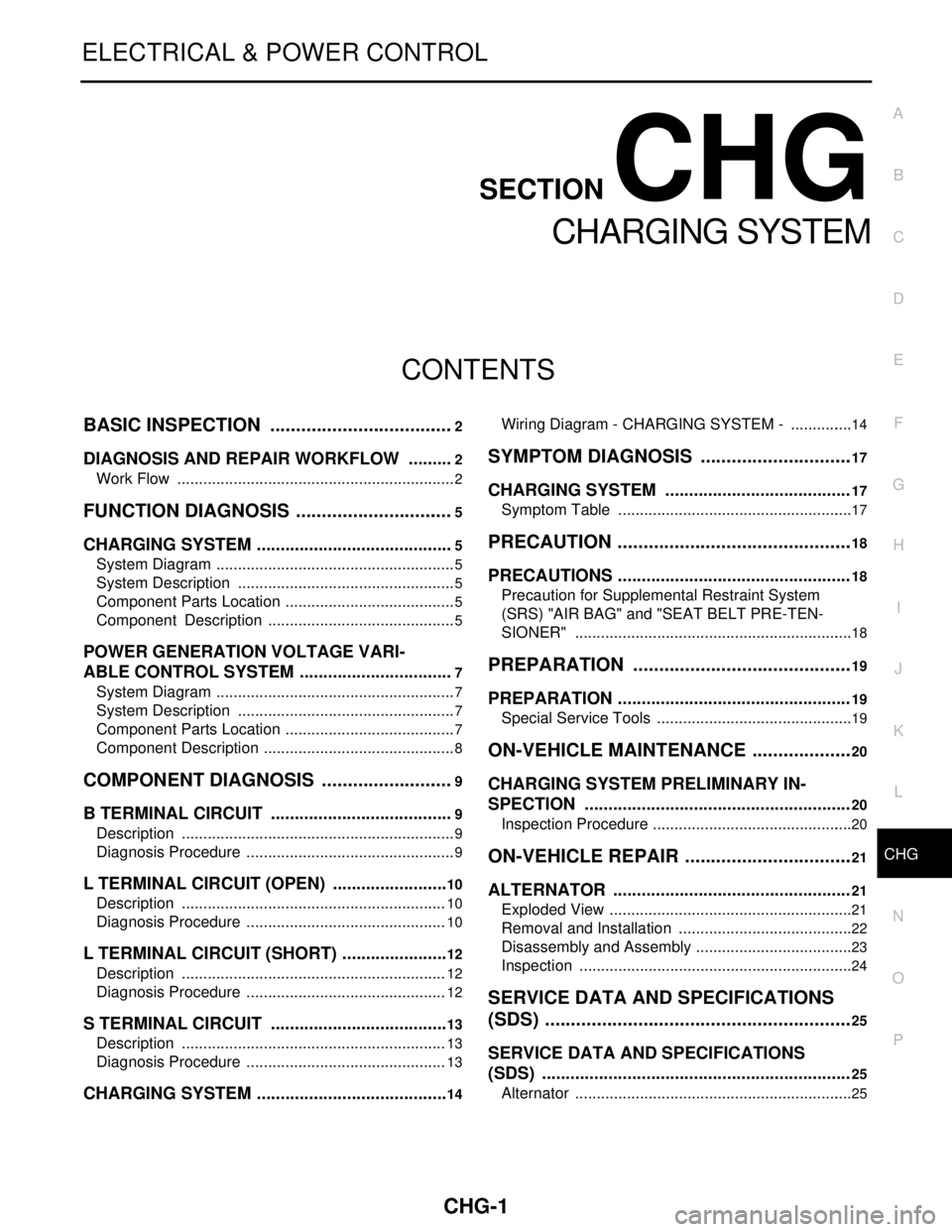
CONTENTS
CHARGING SYSTEM
BASIC INSPECTION .......
.............................2
DIAGNOSIS AND REPAIR WORKFLOW ..... .....2
Work Flow ........................................................... ......2
FUNCTION DIAGNOSIS ...............................5
CHARGING SYSTEM ..................................... .....5
System Diagram .................................................. ......5
System Description ...................................................5
Component Parts Location ........................................5
Component Description ............................................5
POWER GENERATION VOLTAGE VARI-
ABLE CONTROL SYSTEM ............................ .....
7
System Diagram .................................................. ......7
System Description ...................................................7
Component Parts Location ........................................7
Component Description .............................................8
COMPONENT DIAGNOSIS ..........................9
B TERMINAL CIRCUIT .................................. .....9
Description .......................................................... ......9
Diagnosis Procedure .................................................9
L TERMINAL CIRCUIT (OPEN) .........................10
Description .......................................................... ....10
Diagnosis Procedure ...............................................10
L TERMINAL CIRCUIT (SHORT) .......................12
Description .......................................................... ....12
Diagnosis Procedure ...............................................12
S TERMINAL CIRCUIT ......................................13
Description .......................................................... ....13
Diagnosis Procedure ...............................................13
CHARGING SYSTEM ..................................... ....14
Wiring Diagram - CHARGING SYSTEM - ........... ....14
SYMPTOM DIAGNOSIS ..............................17
CHARGING SYSTEM .......................................17
Symptom Table ................................................... ....17
PRECAUTION ..............................................18
PRECAUTIONS .................................................18
Precaution for Supplemental Restraint System
(SRS) "AIR BAG" and "SEAT BELT PRE-TEN-
SIONER" ............................................................. ....
18
PREPARATION ...........................................19
PREPARATION .................................................19
Special Service Tools .......................................... ....19
ON-VEHICLE MAINTENANCE ....................20
CHARGING SYSTEM PRELIMINARY IN-
SPECTION ....... ................................ .................
20
Inspection Procedure ........................................... ....20
ON-VEHICLE REPAIR .................................21
ALTERNATOR . ................................ .................21
Exploded View ..................................................... ....21
Removal and Installation .........................................22
Disassembly and Assembly .....................................23
Inspection ................................................................24
SERVICE DATA AND SPECIFICATIONS
(SDS) ............... .............................................
25
SERVICE DATA AND SPECIFICATIONS
(SDS) .................................................................
25
Alternator ............................................................. ....25
Page 1103 of 5121
CHG
CHARGING SYSTEM
CHG-5
< FUNCTION DIAGNOSIS >
C
D
E
F
G
H
I
J
K
L B A
O
P N
FUNCTION DIAGNOSIS
CHARGING SYSTEM
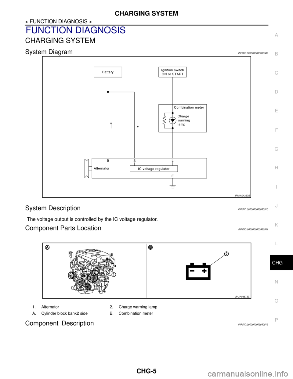
System DiagramINFOID:0000000003860509
System DescriptionINFOID:0000000003860510
The voltage output is controlled by the IC voltage regulator.
Component Parts LocationINFOID:0000000003860511
Component DescriptionINFOID:0000000003860512
JPMIA0426GB
1. Alternator 2. Charge warning lamp
A. Cylinder block bank2 side B. Combination meter
JPLIA0887ZZ
Page 1104 of 5121

CHG-6
< FUNCTION DIAGNOSIS >
CHARGING SYSTEM
Component part Description
AlternatorThe alternator provides DC voltage to operate the vehicle's electri-
cal system and to keep the battery charged.
Combination meter (Charge warning lamp)The IC voltage regulator warning function activates to illuminate
the charge warning lamp, if any of the following symptoms occur
while alternator is operating:
Excessive voltage is produced.
No voltage is produced.
Page 1106 of 5121

CHG-8
< FUNCTION DIAGNOSIS >
POWER GENERATION VOLTAGE VARIABLE CONTROL SYSTEM
Component Description
INFOID:0000000003860520
Component part Description
Battery current sensorBattery current sensor is installed to the battery cable at the neg-
ative terminal, and it detects the charging/discharging current of
the battery and sends the voltage signal to ECM according to the
current value.
ECMBattery current sensor detects the charging/discharging current of
the battery. ECM judges the battery condition based on this signal.
ECM judges whether to perform the power generation voltage
variable control according to the battery condition.
When performing the power generation voltage variable control,
ECM calculates the target power generation voltage according to
the battery condition and sends the calculated value as the power
generation command value to IPDM E/R.
IPDM E/RIPDM E/R converts the received power generation command val-
ue into the power generation command signal (PWM signal) and
sends it to the IC voltage regulator.
Alternator (IC voltage regulator)IC voltage regulator controls the power generation voltage by the
target power generation voltage based on the received power gen-
eration command signal.
When there is no power generation command signal, the alterna-
tor performs the normal power generation according to the char-
acteristic of the IC voltage regulator.
Page 1107 of 5121
CHG
B TERMINAL CIRCUIT
CHG-9
< COMPONENT DIAGNOSIS >
C
D
E
F
G
H
I
J
K
L B A
O
P N
COMPONENT DIAGNOSIS
B TERMINAL CIRCUIT
DescriptionINFOID:0000000003860521
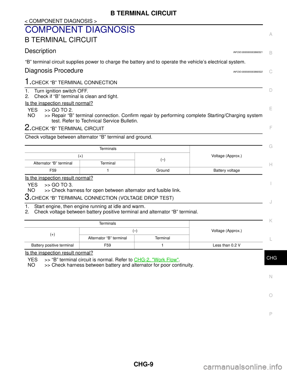
“B” terminal circuit supplies power to charge the battery and to operate the vehicle’s electrical system.
Diagnosis ProcedureINFOID:0000000003860522
1.CHECK “B” TERMINAL CONNECTION
1. Turn ignition switch OFF.
2. Check if “B” terminal is clean and tight.
Is the inspection result normal?
YES >> GO TO 2.
NO >> Repair “B” terminal connection. Confirm repair by performing complete Starting/Charging system
test. Refer to Technical Service Bulletin.
2.CHECK “B” TERMINAL CIRCUIT
Check voltage between alternator “B” terminal and ground.
Is the inspection result normal?
YES >> GO TO 3.
NO >> Check harness for open between alternator and fusible link.
3.CHECK “B” TERMINAL CONNECTION (VOLTAGE DROP TEST)
1. Start engine, then engine running at idle and warm.
2. Check voltage between battery positive terminal and alternator “B” terminal.
Is the inspection result normal?
YES >> “B” terminal circuit is normal. Refer to CHG-2, "Work Flow".
NO >> Check harness between battery and alternator for poor continuity.
Te r m i n a l s
Voltage (Approx.) (+)
(–)
Alternator “B” terminal Terminal
F59 1 Ground Battery voltage
Te r m i n a l s
Voltage (Approx.)
(+)(–)
Alternator “B” terminal Terminal
Battery positive terminal F59 1 Less than 0.2 V
Page 1108 of 5121
CHG-10
< COMPONENT DIAGNOSIS >
L TERMINAL CIRCUIT (OPEN)
L TERMINAL CIRCUIT (OPEN)
DescriptionINFOID:0000000003860523
The “L” terminal circuit controls the charge warning lamp. The charge warning lamp illuminates when the igni-
tion switch is set to ON or START. When the alternator is providing sufficient voltage with the engine running,
the charge warning lamp will go off. If the charge warning lamp illuminates with the engine running, a malfunc-
tion is indicated.
Diagnosis ProcedureINFOID:0000000003860524
1.CHECK “L” TERMINAL CONNECTION
1. Turn ignition switch OFF.
2. Check if “L” terminal is clean and tight.
Is the inspection result normal?
YES >> GO TO 2.
NO >> Repair “L” terminal connection. Confirm repair by performing complete Starting/Charging system
test. Refer to Technical Service Bulletin.
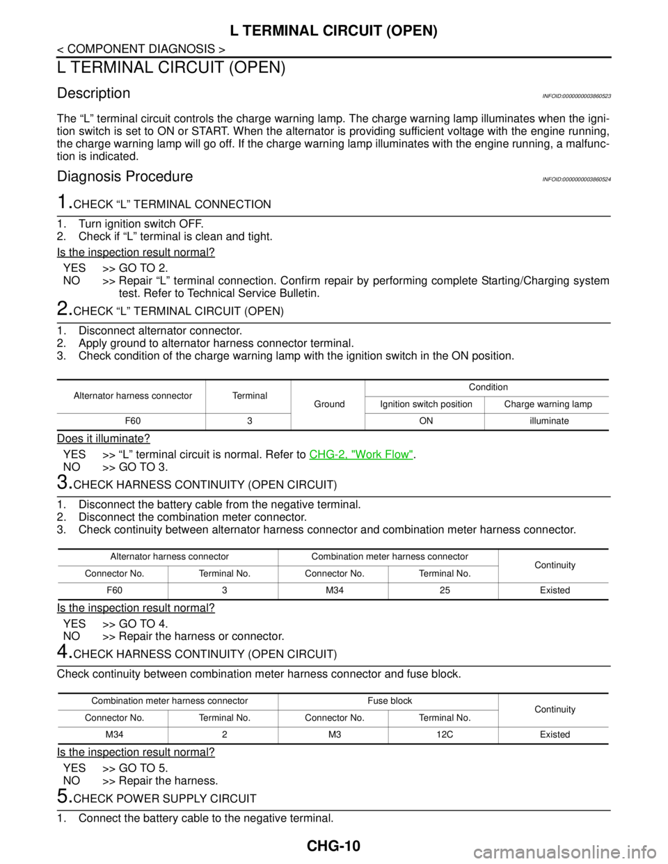
2.CHECK “L” TERMINAL CIRCUIT (OPEN)
1. Disconnect alternator connector.
2. Apply ground to alternator harness connector terminal.
3. Check condition of the charge warning lamp with the ignition switch in the ON position.
Does it illuminate?
YES >> “L” terminal circuit is normal. Refer to CHG-2, "Work Flow".
NO >> GO TO 3.
3.CHECK HARNESS CONTINUITY (OPEN CIRCUIT)
1. Disconnect the battery cable from the negative terminal.
2. Disconnect the combination meter connector.
3. Check continuity between alternator harness connector and combination meter harness connector.
Is the inspection result normal?
YES >> GO TO 4.
NO >> Repair the harness or connector.
4.CHECK HARNESS CONTINUITY (OPEN CIRCUIT)
Check continuity between combination meter harness connector and fuse block.
Is the inspection result normal?
YES >> GO TO 5.
NO >> Repair the harness.
5.CHECK POWER SUPPLY CIRCUIT
1. Connect the battery cable to the negative terminal.
Alternator harness connector Terminal
GroundCondition
Ignition switch position Charge warning lamp
F60 3 ON illuminate
Alternator harness connector Combination meter harness connector
Continuity
Connector No. Terminal No. Connector No. Terminal No.
F60 3 M34 25 Existed
Combination meter harness connector Fuse block
Continuity
Connector No. Terminal No. Connector No. Terminal No.
M34 2 M3 12C Existed
Page 1109 of 5121
CHG
L TERMINAL CIRCUIT (OPEN)
CHG-11
< COMPONENT DIAGNOSIS >
C
D
E
F
G
H
I
J
K
L B A
O
P N
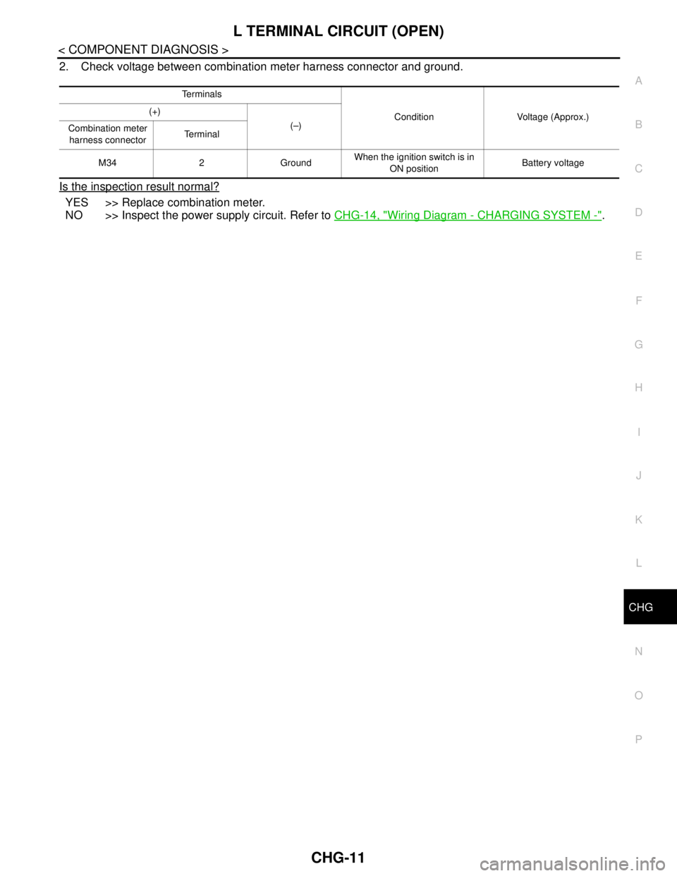
2. Check voltage between combination meter harness connector and ground.
Is the inspection result normal?
YES >> Replace combination meter.
NO >> Inspect the power supply circuit. Refer to CHG-14, "
Wiring Diagram - CHARGING SYSTEM -".
Te r m i n a l s
Condition Voltage (Approx.) (+)
(–)
Combination meter
harness connectorTe r m i n a l
M34 2 GroundWhen the ignition switch is in
ON positionBattery voltage