2008 NISSAN TEANA recommended oil
[x] Cancel search: recommended oilPage 1498 of 5121
![NISSAN TEANA 2008 Service Manual ELECTRIC IGNITION SYSTEM
EC-37
< FUNCTION DIAGNOSIS >[VQ25DE, VQ35DE]
C
D
E
F
G
H
I
J
K
L
MA
EC
N
P O
ELECTRIC IGNITION SYSTEM
System DiagramINFOID:0000000003856469
System DescriptionINFOID:0000000003 NISSAN TEANA 2008 Service Manual ELECTRIC IGNITION SYSTEM
EC-37
< FUNCTION DIAGNOSIS >[VQ25DE, VQ35DE]
C
D
E
F
G
H
I
J
K
L
MA
EC
N
P O
ELECTRIC IGNITION SYSTEM
System DiagramINFOID:0000000003856469
System DescriptionINFOID:0000000003](/manual-img/5/57391/w960_57391-1497.png)
ELECTRIC IGNITION SYSTEM
EC-37
< FUNCTION DIAGNOSIS >[VQ25DE, VQ35DE]
C
D
E
F
G
H
I
J
K
L
MA
EC
N
P O
ELECTRIC IGNITION SYSTEM
System DiagramINFOID:0000000003856469
System DescriptionINFOID:0000000003856470
INPUT/OUTPUT SIGNAL CHART
*1: This signal is sent to the ECM through CAN communication line.
*2: ECM determines the start signal status by the signals of engine speed and battery voltage.
SYSTEM DESCRIPTION
Ignition order: 1 - 2 - 3 - 4 - 5 - 6
The ignition timing is controlled by the ECM to maintain the best air-fuel ratio for every running condition of the
engine. The ignition timing data is stored in the ECM.
The ECM receives information such as the injection pulse width and camshaft position sensor (PHASE) sig-
nal. Computing this information, ignition signals are transmitted to the power transistor.
During the following conditions, the ignition timing is revised by the ECM according to the other data stored in
the ECM.
At starting
During warm-up
At idle
At low battery voltage
During acceleration
The knock sensor retard system is designed only for emergencies. The basic ignition timing is programmed
within the anti-knocking zone, if recommended fuel is used under dry conditions. The retard system does not
JMBIA1493GB
Sensor Input Signal to ECM ECM function Actuator
Crankshaft position sensor (POS)
Engine speed*
2
Piston position
Ignition timing
controlIgnition coil
(with power transistor) Camshaft position sensor (PHASE)
Mass air flow sensor Amount of intake air
Engine coolant temperature sensor Engine coolant temperature
Throttle position sensor Throttle position
Accelerator pedal position sensor Accelerator pedal position
Battery
Battery voltage*
2
Knock sensor Engine knocking
TCM (VQ35DE engine)
Park/neutral position (PNP) switch (VQ25DE engine)Gear position
ABS actuator and electric unit (control unit)
Vehicle speed*
1
Page 2519 of 5121
GI-26
< PRECAUTION >
PRECAUTIONS
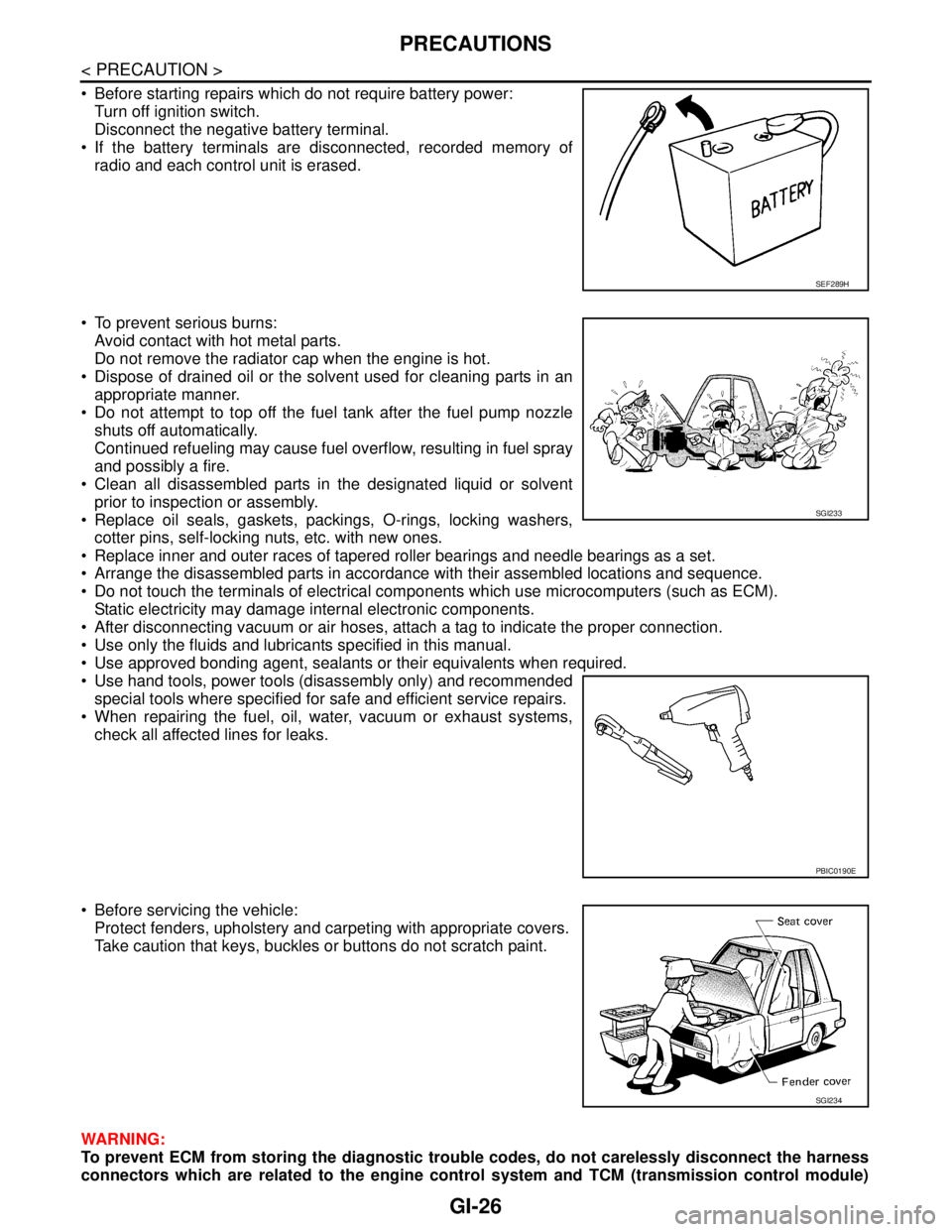
Before starting repairs which do not require battery power:
Turn off ignition switch.
Disconnect the negative battery terminal.
If the battery terminals are disconnected, recorded memory of
radio and each control unit is erased.
To prevent serious burns:
Avoid contact with hot metal parts.
Do not remove the radiator cap when the engine is hot.
Dispose of drained oil or the solvent used for cleaning parts in an
appropriate manner.
Do not attempt to top off the fuel tank after the fuel pump nozzle
shuts off automatically.
Continued refueling may cause fuel overflow, resulting in fuel spray
and possibly a fire.
Clean all disassembled parts in the designated liquid or solvent
prior to inspection or assembly.
Replace oil seals, gaskets, packings, O-rings, locking washers,
cotter pins, self-locking nuts, etc. with new ones.
Replace inner and outer races of tapered roller bearings and needle bearings as a set.
Arrange the disassembled parts in accordance with their assembled locations and sequence.
Do not touch the terminals of electrical components which use microcomputers (such as ECM).
Static electricity may damage internal electronic components.
After disconnecting vacuum or air hoses, attach a tag to indicate the proper connection.
Use only the fluids and lubricants specified in this manual.
Use approved bonding agent, sealants or their equivalents when required.
Use hand tools, power tools (disassembly only) and recommended
special tools where specified for safe and efficient service repairs.
When repairing the fuel, oil, water, vacuum or exhaust systems,
check all affected lines for leaks.
Before servicing the vehicle:
Protect fenders, upholstery and carpeting with appropriate covers.
Take caution that keys, buckles or buttons do not scratch paint.
WARNING:
To prevent ECM from storing the diagnostic trouble codes, do not carelessly disconnect the harness
connectors which are related to the engine control system and TCM (transmission control module)
SEF289H
SGI233
PBIC0190E
SGI234
Page 2585 of 5121
HA-16
< PRECAUTION >
PRECAUTIONS
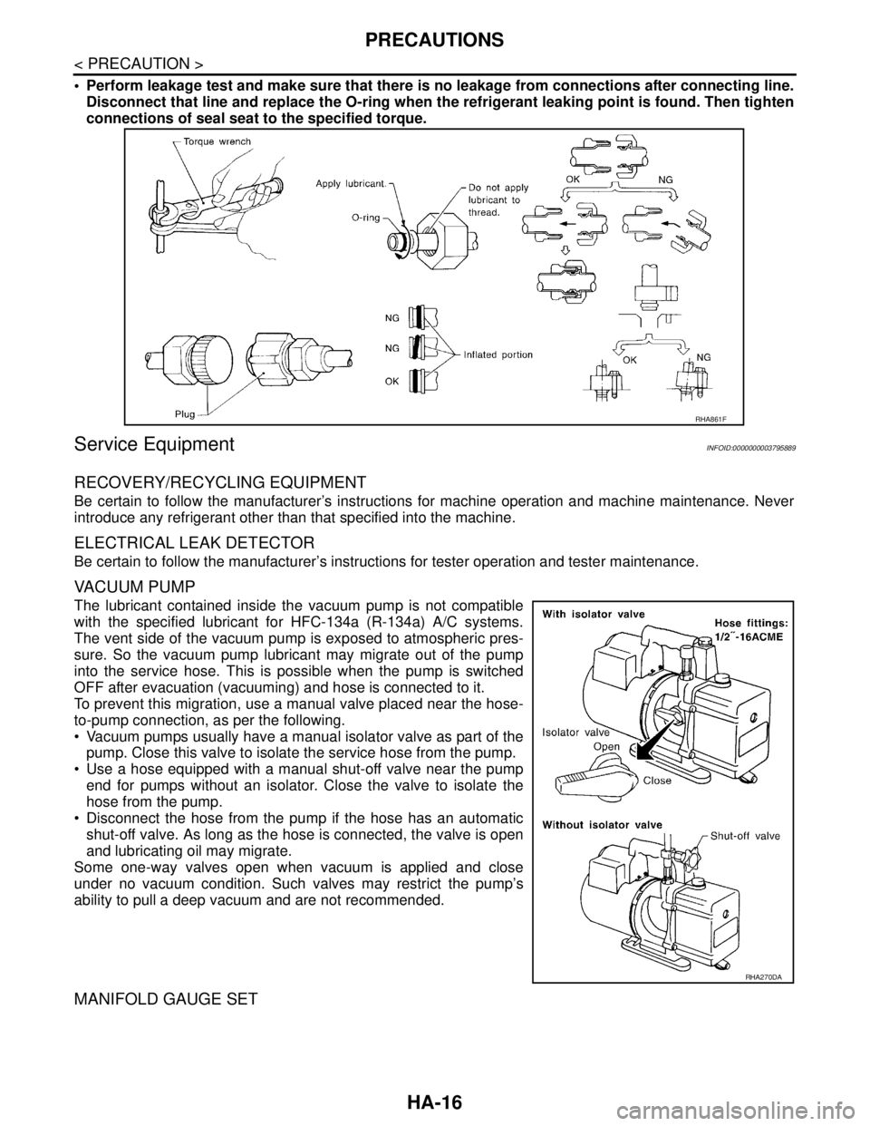
Perform leakage test and make sure that there is no leakage from connections after connecting line.
Disconnect that line and replace the O-ring when the refrigerant leaking point is found. Then tighten
connections of seal seat to the specified torque.
Service EquipmentINFOID:0000000003795889
RECOVERY/RECYCLING EQUIPMENT
Be certain to follow the manufacturer’s instructions for machine operation and machine maintenance. Never
introduce any refrigerant other than that specified into the machine.
ELECTRICAL LEAK DETECTOR
Be certain to follow the manufacturer’s instructions for tester operation and tester maintenance.
VACUUM PUMP
The lubricant contained inside the vacuum pump is not compatible
with the specified lubricant for HFC-134a (R-134a) A/C systems.
The vent side of the vacuum pump is exposed to atmospheric pres-
sure. So the vacuum pump lubricant may migrate out of the pump
into the service hose. This is possible when the pump is switched
OFF after evacuation (vacuuming) and hose is connected to it.
To prevent this migration, use a manual valve placed near the hose-
to-pump connection, as per the following.
Vacuum pumps usually have a manual isolator valve as part of the
pump. Close this valve to isolate the service hose from the pump.
Use a hose equipped with a manual shut-off valve near the pump
end for pumps without an isolator. Close the valve to isolate the
hose from the pump.
Disconnect the hose from the pump if the hose has an automatic
shut-off valve. As long as the hose is connected, the valve is open
and lubricating oil may migrate.
Some one-way valves open when vacuum is applied and close
under no vacuum condition. Such valves may restrict the pump’s
ability to pull a deep vacuum and are not recommended.
MANIFOLD GAUGE SET
RHA861F
RHA270DA
Page 2730 of 5121
![NISSAN TEANA 2008 Service Manual HAC-102
< PRECAUTION >[WITHOUT 7 INCH DISPLAY]
PRECAUTIONS
The lubricant contained inside the vacuum pump is not compatible
with the specified lubricant for HFC-134a (R-134a) A/C systems.
The vent sid NISSAN TEANA 2008 Service Manual HAC-102
< PRECAUTION >[WITHOUT 7 INCH DISPLAY]
PRECAUTIONS
The lubricant contained inside the vacuum pump is not compatible
with the specified lubricant for HFC-134a (R-134a) A/C systems.
The vent sid](/manual-img/5/57391/w960_57391-2729.png)
HAC-102
< PRECAUTION >[WITHOUT 7 INCH DISPLAY]
PRECAUTIONS
The lubricant contained inside the vacuum pump is not compatible
with the specified lubricant for HFC-134a (R-134a) A/C systems.
The vent side of the vacuum pump is exposed to atmospheric pres-
sure. So the vacuum pump lubricant may migrate out of the pump
into the service hose. This is possible when the pump is switched
OFF after evacuation (vacuuming) and hose is connected to it.
To prevent this migration, use a manual valve placed near the hose-
to-pump connection, as per the following.
Vacuum pumps usually have a manual isolator valve as part of the
pump. Close this valve to isolate the service hose from the pump.
Use a hose equipped with a manual shut-off valve near the pump
end for pumps without an isolator. Close the valve to isolate the
hose from the pump.
Disconnect the hose from the pump if the hose has an automatic
shut-off valve. As long as the hose is connected, the valve is open
and lubricating oil may migrate.
Some one-way valves open when vacuum is applied and close
under no vacuum condition. Such valves may restrict the ability of
the pump to create a deep vacuum and are not recommended.
MANIFOLD GAUGE SET
Be certain that the gauge face indicates HFC-134a or R-134a. Be
sure the gauge set has 1/2″-16 ACME threaded connections for ser-
vice hoses. Confirm the set has been used only with refrigerant
HFC-134a (R-134a) and specified lubricants.
SERVICE HOSES
Be certain that the service hoses display the markings described
(colored hose with a black stripe). All hoses must equip positive
shut-off devices (either manual or automatic) near the end of the
hoses opposite to the manifold gauge.
SERVICE COUPLERS
RHA270DA
SHA533D
RHA272D
Page 2870 of 5121
![NISSAN TEANA 2008 Service Manual HAC-242
< PRECAUTION >[WITH 7 INCH DISPLAY]
PRECAUTIONS
The lubricant contained inside the vacuum pump is not compatible
with the specified lubricant for HFC-134a (R-134a) A/C systems.
The vent side o NISSAN TEANA 2008 Service Manual HAC-242
< PRECAUTION >[WITH 7 INCH DISPLAY]
PRECAUTIONS
The lubricant contained inside the vacuum pump is not compatible
with the specified lubricant for HFC-134a (R-134a) A/C systems.
The vent side o](/manual-img/5/57391/w960_57391-2869.png)
HAC-242
< PRECAUTION >[WITH 7 INCH DISPLAY]
PRECAUTIONS
The lubricant contained inside the vacuum pump is not compatible
with the specified lubricant for HFC-134a (R-134a) A/C systems.
The vent side of the vacuum pump is exposed to atmospheric pres-
sure. So the vacuum pump lubricant may migrate out of the pump
into the service hose. This is possible when the pump is switched
OFF after evacuation (vacuuming) and hose is connected to it.
To prevent this migration, use a manual valve placed near the hose-
to-pump connection, as per the following.
Vacuum pumps usually have a manual isolator valve as part of the
pump. Close this valve to isolate the service hose from the pump.
Use a hose equipped with a manual shut-off valve near the pump
end for pumps without an isolator. Close the valve to isolate the
hose from the pump.
Disconnect the hose from the pump if the hose has an automatic
shut-off valve. As long as the hose is connected, the valve is open
and lubricating oil may migrate.
Some one-way valves open when vacuum is applied and close
under no vacuum condition. Such valves may restrict the ability of
the pump to create a deep vacuum and are not recommended.
MANIFOLD GAUGE SET
Be certain that the gauge face indicates HFC-134a or R-134a. Be
sure the gauge set has 1/2″-16 ACME threaded connections for ser-
vice hoses. Confirm the set has been used only with refrigerant
HFC-134a (R-134a) and specified lubricants.
SERVICE HOSES
Be certain that the service hoses display the markings described
(colored hose with a black stripe). All hoses must equip positive
shut-off devices (either manual or automatic) near the end of the
hoses opposite to the manifold gauge.
SERVICE COUPLERS
RHA270DA
SHA533D
RHA272D
Page 3189 of 5121
MA-1
MAINTENANCE
C
DE
F
G H
I
J
K L
M B
MA
SECTION MA
N
O A
CONTENTS
MAINTENANCE
PREPARATION .............
...............................3
PREPARATION .............................................. .....3
Special Service Tool ........................................... ......3
Commercial Service Tool ..........................................3
Pre-Delivery Inspection Item .....................................3
ON-VEHICLE MAINTENANCE .....................5
GENERAL MAINTENANCE ........................... .....5
General Maintenance .......................................... ......5
PERIODIC MAINTENANCE ................................6
Periodic Maintenance .......................................... ......6
RECOMMENDED FLUIDS AND LUBRI-
CANTS ................................................................
11
Fluids and Lubricants .......................................... ....11
SAE Viscosity Number ............................................11
Engine Coolant Mixture Ratio .................................12
ENGINE MAINTENANCE ...................................13
DRIVE BELT .......................................................... ....13
DRIVE BELT : Exploded View ................................13
DRIVE BELT : Checking .........................................13
DRIVE BELT : Tension Adjustment ........................13
ENGINE COOLANT ............................................... ....13
ENGINE COOLANT : Inspection .............................13
ENGINE COOLANT : Draining ................................14
ENGINE COOLANT : Refilling ................................14
ENGINE COOLANT : Flushing ...............................16
RADIATOR CAP .................................................... ....16
RADIATOR CAP : Inspection ..................................17
RADIATOR ............................................................ ....17
RADIATOR : Inspection ..........................................17
FUEL LINES .......................................................... ....17
FUEL LINES : Inspection ........................................18
AIR CLEANER FILTER ......................................... ....18
AIR CLEANER FILTER : Removal and Installation
....
18
ENGINE OIL ........................................................... ....18
ENGINE OIL : Draining ............................................18
ENGINE OIL : Refilling ............................................19
OIL FILTER ............................................................ ....19
OIL FILTER : Removal and Installation ...................19
OIL FILTER : Inspection ..........................................20
SPARK PLUG ........................................................ ....20
SPARK PLUG : Removal and Installation ...............20
SPARK PLUG : Inspection ......................................21
POSITIVE CRANKCASE VENTILATION SYSTEM ....21
POSITIVE CRANKCASE VENTILATION SYS-
TEM : Inspection ......................................................
21
EVAP VAPOR LINES ............................................ ....22
EVAP VAPOR LINES : Inspection ...........................22
CHASSIS MAINTENANCE ...............................23
HEADLAMP AIMING ADJUSTMENT (XENON
TYPE) .......... ................................. ..............................
23
HEADLAMP AIMING ADJUSTMENT (XENON
TYPE) : Description ............................................. ....
23
HEADLAMP AIMING ADJUSTMENT (XENON
TYPE) : Aiming Adjustment Procedure (Low
Beam) ......................................................................
24
HEADLAMP AIMING ADJUSTMENT (XENON
TYPE) : Aiming Adjustment Procedure (High
Beam) ......................................................................
25
HEADLAMP AIMING ADJUSTMENT (HALOGEN
TYPE) ........................................... ..............................
27
HEADLAMP AIMING ADJUSTMENT (HALOGEN
TYPE) : Description ............................................. ....
27
HEADLAMP AIMING ADJUSTMENT (HALOGEN
TYPE) : Aiming Adjustment Procedure (Low
Beam) ......................................................................
29
Page 3191 of 5121
PREPARATION
MA-3
< PREPARATION >
C
D
E
F
G
H
I
J
K
L
MB
MAN
OA
PREPARATION
PREPARATION
Special Service ToolINFOID:0000000003858218
Commercial Service ToolINFOID:0000000003858219
Pre-Delivery Inspection ItemINFOID:0000000003858220
Shown below are Pre-delivery Inspection Items required for the new vehicle. It is recommended that
necessary items other than those listed here be added, paying due regard to the conditions in each
country.
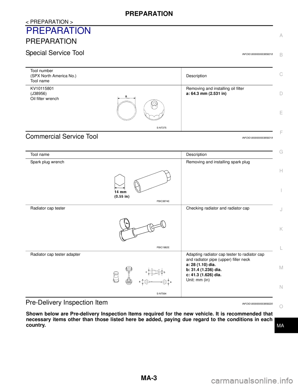
Tool number
(SPX North America No.)
Tool nameDescription
KV10115801
(J38956)
Oil filter wrenchRemoving and installing oil filter
a: 64.3 mm (2.531 in)
S-NT375
Tool nameDescription
Spark plug wrench Removing and installing spark plug
Radiator cap tester Checking radiator and radiator cap
Radiator cap tester adapter Adapting radiator cap tester to radiator cap
and radiator pipe (upper) filler neck
a: 28 (1.10) dia.
b: 31.4 (1.236) dia.
c: 41.3 (1.626) dia.
Unit: mm (in)
PBIC3874E
PBIC1982E
S-NT564
Page 3194 of 5121
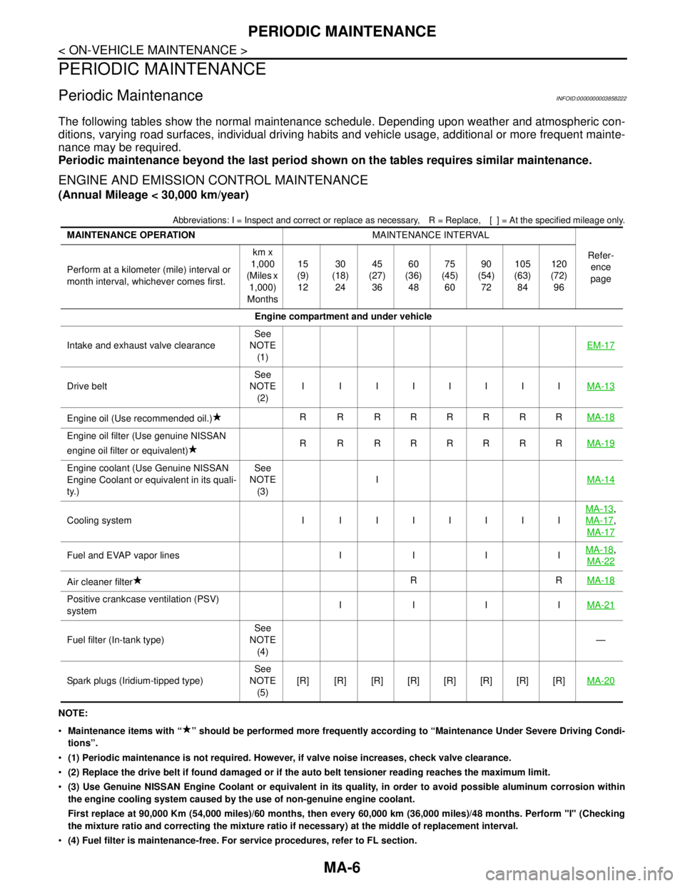
MA-6
< ON-VEHICLE MAINTENANCE >
PERIODIC MAINTENANCE
PERIODIC MAINTENANCE
Periodic MaintenanceINFOID:0000000003858222
The following tables show the normal maintenance schedule. Depending upon weather and atmospheric con-
ditions, varying road surfaces, individual driving habits and vehicle usage, additional or more frequent mainte-
nance may be required.
Periodic maintenance beyond the last period shown on the tables requires similar maintenance.
ENGINE AND EMISSION CONTROL MAINTENANCE
(Annual Mileage < 30,000 km/year)
Abbreviations: I = Inspect and correct or replace as necessary, R = Replace,[ ] = At the specified mileage only.
NOTE:
Maintenance items with “ ” should be performed more frequently according to “Maintenance Under Severe Driving Condi-
tions”.
(1) Periodic maintenance is not required. However, if valve noise increases, check valve clearance.
(2) Replace the drive belt if found damaged or if the auto belt tensioner reading reaches the maximum limit.
(3) Use Genuine NISSAN Engine Coolant or equivalent in its quality, in order to avoid possible aluminum corrosion within
the engine cooling system caused by the use of non-genuine engine coolant.
First replace at 90,000 Km (54,000 miles)/60 months, then every 60,000 km (36,000 miles)/48 months. Perform "I" (Checking
the mixture ratio and correcting the mixture ratio if necessary) at the middle of replacement interval.
(4) Fuel filter is maintenance-free. For service procedures, refer to FL section. MAINTENANCE OPERATIONMAINTENANCE INTERVAL
Refer-
ence
page Perform at a kilometer (mile) interval or
month interval, whichever comes first.km x
1,000
(Miles x
1,000)
Months15
(9)
1230
(18)
2445
(27)
3660
(36)
4875
(45)
6090
(54)
72105
(63)
84120
(72)
96
Engine compartment and under vehicle
Intake and exhaust valve clearanceSee
NOTE
(1)EM-17
Drive beltSee
NOTE
(2)I I IIIIIIMA-13
Engine oil (Use recommended oil.)R R RRRRRRMA-18
Engine oil filter (Use genuine NISSAN
engine oil filter or equivalent)R R RRRRRRMA-19
Engine coolant (Use Genuine NISSAN
Engine Coolant or equivalent in its quali-
ty.)See
NOTE
(3)IMA-14
Cooling system I I IIIIIIMA-13
,
MA-17
,
MA-17
Fuel and EVAP vapor lines I I I IMA-18,
MA-22
Air cleaner filterRRMA-18
Positive crankcase ventilation (PSV)
systemIIIIMA-21
Fuel filter (In-tank type)See
NOTE
(4)—
Spark plugs (Iridium-tipped type)See
NOTE
(5)[R] [R] [R] [R] [R] [R] [R] [R]MA-20