2008 NISSAN TEANA recommended oil
[x] Cancel search: recommended oilPage 3196 of 5121
MA-8
< ON-VEHICLE MAINTENANCE >
PERIODIC MAINTENANCE
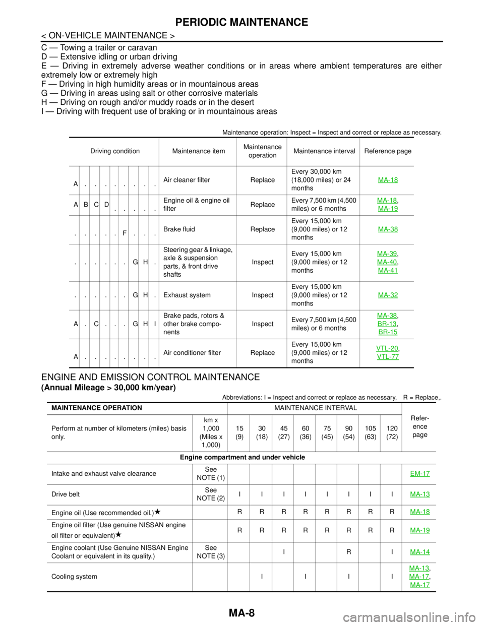
C — Towing a trailer or caravan
D — Extensive idling or urban driving
E — Driving in extremely adverse weather conditions or in areas where ambient temperatures are either
extremely low or extremely high
F — Driving in high humidity areas or in mountainous areas
G — Driving in areas using salt or other corrosive materials
H — Driving on rough and/or muddy roads or in the desert
I — Driving with frequent use of braking or in mountainous areas
Maintenance operation: Inspect = Inspect and correct or replace as necessary.
ENGINE AND EMISSION CONTROL MAINTENANCE
(Annual Mileage > 30,000 km/year)
Abbreviations: I = Inspect and correct or replace as necessary, R = Replace,.
Driving condition Maintenance itemMaintenance
operationMaintenance interval Reference page
A........Air cleaner filter ReplaceEvery 30,000 km
(18,000 miles) or 24
monthsMA-18
ABCD
.....Engine oil & engine oil
filter ReplaceEvery 7,500 km (4,500
miles) or 6 monthsMA-18,
MA-19
.....F...Brake fluid ReplaceEvery 15,000 km
(9,000 miles) or 12
monthsMA-38
......GH.Steering gear & linkage,
axle & suspension
parts, & front drive
shafts InspectEvery 15,000 km
(9,000 miles) or 12
monthsMA-39
,
MA-40
,
MA-41
. . . . . . G H . Exhaust system InspectEvery 15,000 km
(9,000 miles) or 12
monthsMA-32
A. C. . . GHIBrake pads, rotors &
other brake compo-
nentsInspectEvery 7,500 km (4,500
miles) or 6 monthsMA-38
,
BR-13
,
BR-15
A........Air conditioner filter ReplaceEvery 15,000 km
(9,000 miles) or 12
monthsVTL-20
,
VTL-77
MAINTENANCE OPERATIONMAINTENANCE INTERVAL
Refer-
ence
page Perform at number of kilometers (miles) basis
only.km x
1,000
(Miles x
1,000)15
(9)30
(18)45
(27)60
(36)75
(45)90
(54)105
(63)120
(72)
Engine compartment and under vehicle
Intake and exhaust valve clearanceSee
NOTE (1)EM-17
Drive beltSee
NOTE (2)I I IIIIIIMA-13
Engine oil (Use recommended oil.)R RRRRRRRMA-18
Engine oil filter (Use genuine NISSAN engine
oil filter or equivalent)R RRRRRRRMA-19
Engine coolant (Use Genuine NISSAN Engine
Coolant or equivalent in its quality.)See
NOTE (3)IRIMA-14
Cooling system I I I IMA-13
,
MA-17
,
MA-17
Page 3199 of 5121

RECOMMENDED FLUIDS AND LUBRICANTS
MA-11
< ON-VEHICLE MAINTENANCE >
C
D
E
F
G
H
I
J
K
L
MB
MAN
OA
RECOMMENDED FLUIDS AND LUBRICANTS
Fluids and LubricantsINFOID:0000000003858223
*1: For further details, see “SAE Viscosity Number”.
*2: Use Genuine NISSAN Engine Coolant or equivalent in its quality, in order to avoid possible aluminum corrosion within the engine
cooling system caused by the use of non-genuine engine coolant.
Note that any repairs for the incidents within the engine cooling system while using non-genuine engine coolant may not be
covered by the warranty even if such incidents occurred during the warranty period.
*3: Using transmission fluid other than Genuine NISSAN CVT fluid NS-2 will damage the CVT, which is not covered by the war-
ranty.
*4: DEXRON
™ VI type ATF can be used.
*5: Never mix different types of fluids (DOT3 and DOT4).
SAE Viscosity NumberINFOID:0000000003858224
GASOLINE ENGINE
5W-30 is preferable.
Capacity (Approximate)
Recommended Fluids/Lubricants
LiterImp mea-
sure
Engine oil
Drain and refillWith oil filter change 4.6 4 qt
Genuine NISSAN engine oil
*1
API grade SL or SM*1
ILSAC grade GF-3 or GF-4*1
ACEA A1/B1, A3/B3, A3/B4, A5/B5, C2 or C3*1
Without oil filter
change4.3 3-3/4 qt
Dry engine (engine overhaul) 5.3 4-5/8 qt
Cooling system (with reservoir) 9.1 8 qt
Genuine NISSAN Engine Coolant or equivalent
in its quality
*2Reservoir tank 0.8 3/4 qt
CVT fluidRE0F10A 8.3 7-1/4 qt
Genuine NISSAN CVT Fluid NS-2
*3
RE0F09B 10.2 9 qt
Power steering fluid 1.0 7/8 qt
Genuine NISSAN PSF or equivalent
*4
Brake fluid — —Genuine NISSAN brake fluid, or equivalent DOT
3 or DOT4 (US FMVSS No. 116)*5
Multi-purpose grease — — NLGI No. 2 (Lithium soap base)
Page 3228 of 5121
MA-40
< ON-VEHICLE MAINTENANCE >
CHASSIS MAINTENANCE
POWER STEERING FLUID AND LINES : Inspection
INFOID:0000000003862441
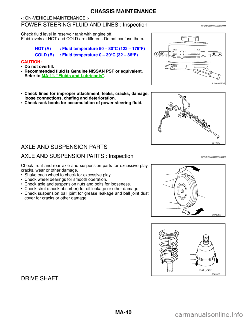
Check fluid level in reservoir tank with engine off.
Fluid levels at HOT and COLD are different. Do not confuse them.
CAUTION:
Do not overfill.
Recommended fluid is Genuine NISSAN PSF or equivalent.
Refer to MA-11, "
Fluids and Lubricants".
Check lines for improper attachment, leaks, cracks, damage,
loose connections, chafing and deterioration.
Check rack boots for accumulation of power steering fluid.
AXLE AND SUSPENSION PARTS
AXLE AND SUSPENSION PARTS : InspectionINFOID:0000000003858316
Check front and rear axle and suspension parts for excessive play,
cracks, wear or other damage.
Shake each wheel to check for excessive play.
Check wheel bearings for smooth operation.
Check axle and suspension nuts and bolts for looseness.
Check strut (shock absorber) for oil leakage or other damage.
Check suspension ball joint for grease leakage and ball joint dust
cover for cracks or other damage.
DRIVE SHAFT
HOT (A) : Fluid temperature 50 – 80°C (122 – 176°F)
COLD (B) : Fluid temperature 0 – 30°C (32 – 86°F)
ALGIA0002GB
SST851C
SMA525A
SFA392B
Page 4397 of 5121
POWER STEERING FLUID
ST-7
< ON-VEHICLE MAINTENANCE >
C
D
E
F
H
I
J
K
L
MA
B
ST
N
O
P
ON-VEHICLE MAINTENANCE
POWER STEERING FLUID
InspectionINFOID:0000000003826225
FLUID LEVEL
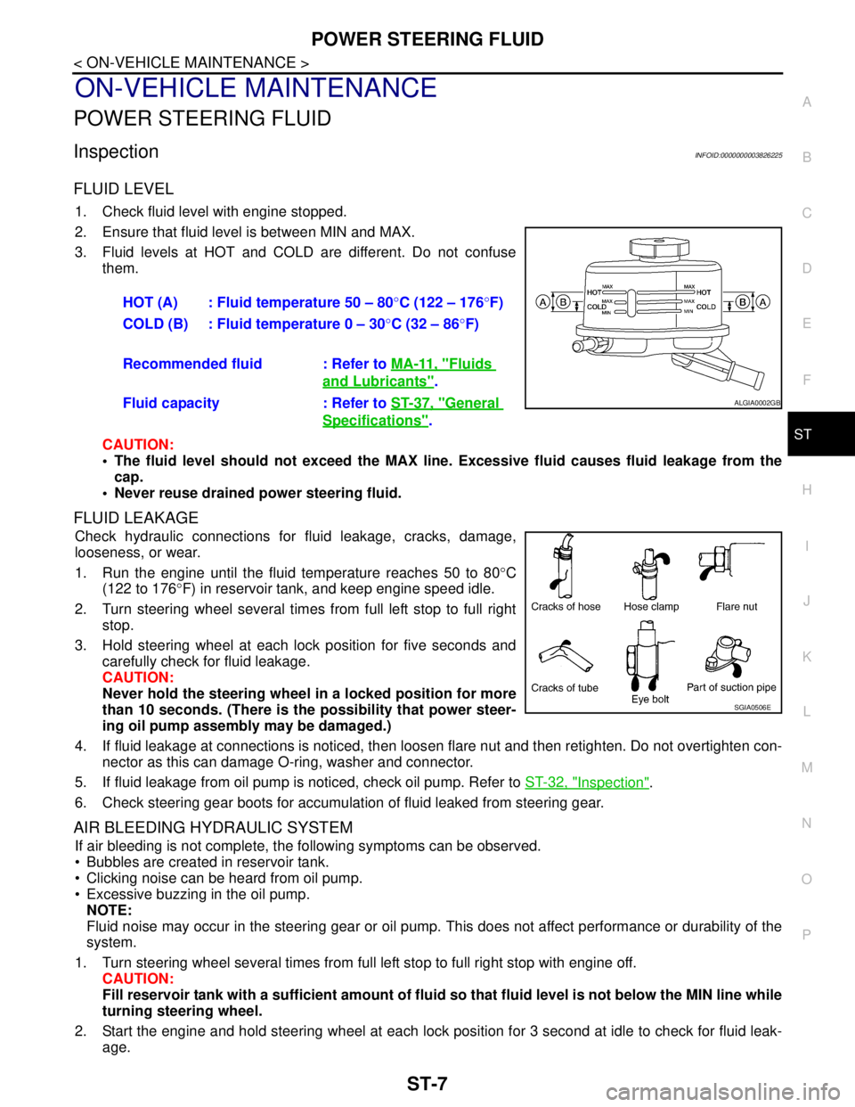
1. Check fluid level with engine stopped.
2. Ensure that fluid level is between MIN and MAX.
3. Fluid levels at HOT and COLD are different. Do not confuse
them.
CAUTION:
The fluid level should not exceed the MAX line. Excessive fluid causes fluid leakage from the
cap.
Never reuse drained power steering fluid.
FLUID LEAKAGE
Check hydraulic connections for fluid leakage, cracks, damage,
looseness, or wear.
1. Run the engine until the fluid temperature reaches 50 to 80°C
(122 to 176°F) in reservoir tank, and keep engine speed idle.
2. Turn steering wheel several times from full left stop to full right
stop.
3. Hold steering wheel at each lock position for five seconds and
carefully check for fluid leakage.
CAUTION:
Never hold the steering wheel in a locked position for more
than 10 seconds. (There is the possibility that power steer-
ing oil pump assembly may be damaged.)
4. If fluid leakage at connections is noticed, then loosen flare nut and then retighten. Do not overtighten con-
nector as this can damage O-ring, washer and connector.
5. If fluid leakage from oil pump is noticed, check oil pump. Refer to ST-32, "
Inspection".
6. Check steering gear boots for accumulation of fluid leaked from steering gear.
AIR BLEEDING HYDRAULIC SYSTEM
If air bleeding is not complete, the following symptoms can be observed.
Bubbles are created in reservoir tank.
Clicking noise can be heard from oil pump.
Excessive buzzing in the oil pump.
NOTE:
Fluid noise may occur in the steering gear or oil pump. This does not affect performance or durability of the
system.
1. Turn steering wheel several times from full left stop to full right stop with engine off.
CAUTION:
Fill reservoir tank with a sufficient amount of fluid so that fluid level is not below the MIN line while
turning steering wheel.
2. Start the engine and hold steering wheel at each lock position for 3 second at idle to check for fluid leak-
age.HOT (A) : Fluid temperature 50 – 80°C (122 – 176°F)
COLD (B) : Fluid temperature 0 – 30°C (32 – 86°F)
Recommended fluid : Refer to MA-11, "
Fluids
and Lubricants".
Fluid capacity : Refer to ST-37, "
General
Specifications".
ALGIA0002GB
SGIA0506E
Page 4411 of 5121
STEERING GEAR AND LINKAGE
ST-21
< ON-VEHICLE REPAIR >
C
D
E
F
H
I
J
K
L
MA
B
ST
N
O
P
Never damage inner socket and gear housing assembly when removing boot. Inner socket and
gear housing assembly must be replaced if inner socket and gear housing assembly are damaged
because it may cause foreign material interfusion.
9. Remove inner socket and spacer from gear housing assembly.
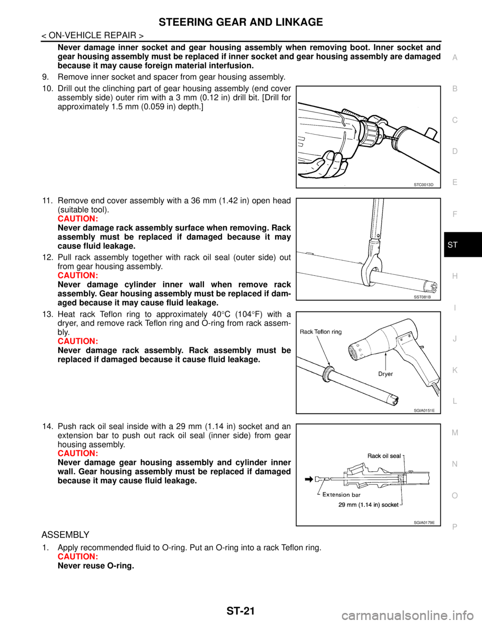
10. Drill out the clinching part of gear housing assembly (end cover
assembly side) outer rim with a 3 mm (0.12 in) drill bit. [Drill for
approximately 1.5 mm (0.059 in) depth.]
11. Remove end cover assembly with a 36 mm (1.42 in) open head
(suitable tool).
CAUTION:
Never damage rack assembly surface when removing. Rack
assembly must be replaced if damaged because it may
cause fluid leakage.
12. Pull rack assembly together with rack oil seal (outer side) out
from gear housing assembly.
CAUTION:
Never damage cylinder inner wall when remove rack
assembly. Gear housing assembly must be replaced if dam-
aged because it may cause fluid leakage.
13. Heat rack Teflon ring to approximately 40°C (104°F) with a
dryer, and remove rack Teflon ring and O-ring from rack assem-
bly.
CAUTION:
Never damage rack assembly. Rack assembly must be
replaced if damaged because it cause fluid leakage.
14. Push rack oil seal inside with a 29 mm (1.14 in) socket and an
extension bar to push out rack oil seal (inner side) from gear
housing assembly.
CAUTION:
Never damage gear housing assembly and cylinder inner
wall. Gear housing assembly must be replaced if damaged
because it may cause fluid leakage.
ASSEMBLY
1. Apply recommended fluid to O-ring. Put an O-ring into a rack Teflon ring.
CAUTION:
Never reuse O-ring.
STC0013D
SST081B
SGIA0151E
SGIA0179E
Page 4412 of 5121
ST-22
< ON-VEHICLE REPAIR >
STEERING GEAR AND LINKAGE
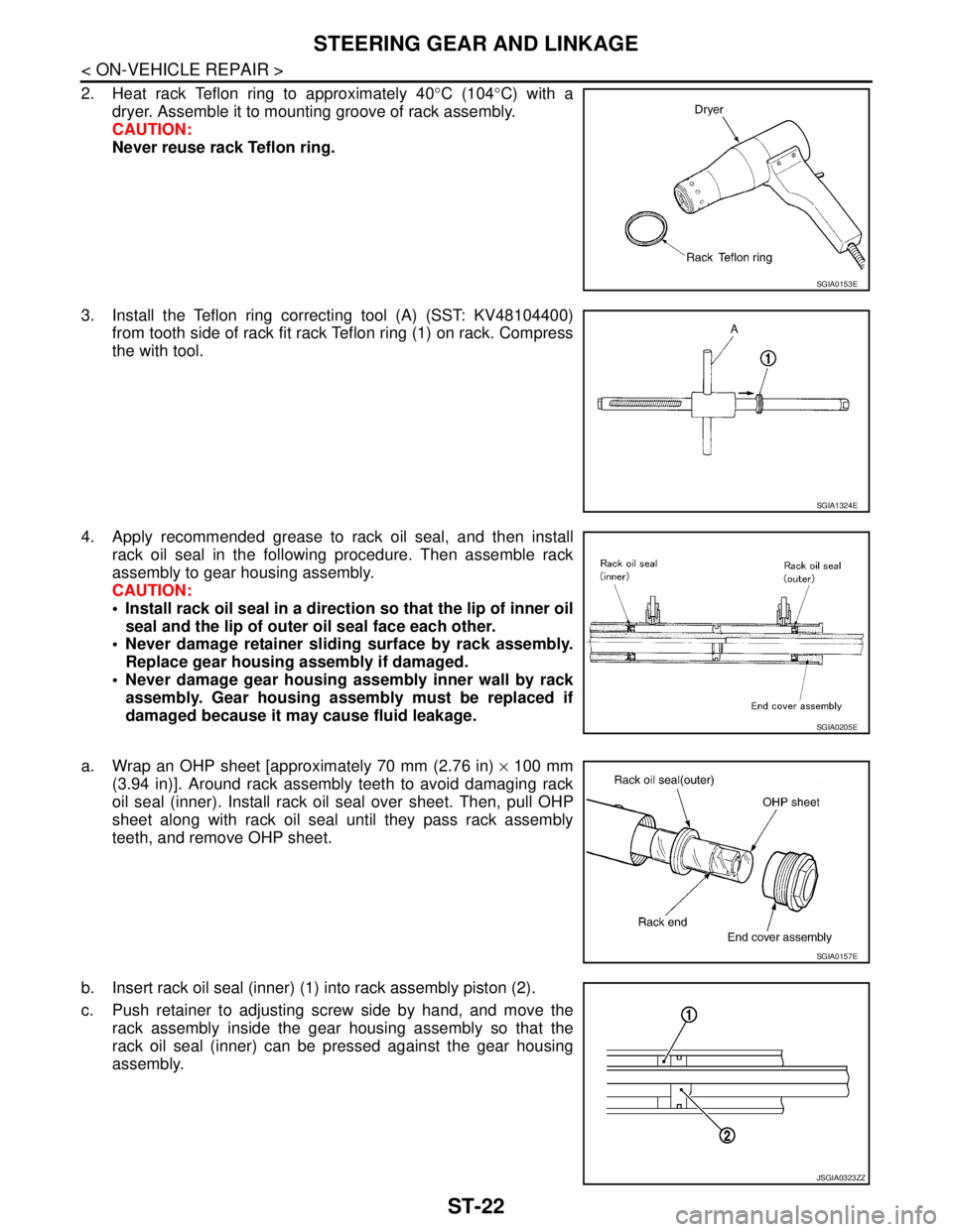
2. Heat rack Teflon ring to approximately 40°C (104°C) with a
dryer. Assemble it to mounting groove of rack assembly.
CAUTION:
Never reuse rack Teflon ring.
3. Install the Teflon ring correcting tool (A) (SST: KV48104400)
from tooth side of rack fit rack Teflon ring (1) on rack. Compress
the with tool.
4. Apply recommended grease to rack oil seal, and then install
rack oil seal in the following procedure. Then assemble rack
assembly to gear housing assembly.
CAUTION:
Install rack oil seal in a direction so that the lip of inner oil
seal and the lip of outer oil seal face each other.
Never damage retainer sliding surface by rack assembly.
Replace gear housing assembly if damaged.
Never damage gear housing assembly inner wall by rack
assembly. Gear housing assembly must be replaced if
damaged because it may cause fluid leakage.
a. Wrap an OHP sheet [approximately 70 mm (2.76 in) × 100 mm
(3.94 in)]. Around rack assembly teeth to avoid damaging rack
oil seal (inner). Install rack oil seal over sheet. Then, pull OHP
sheet along with rack oil seal until they pass rack assembly
teeth, and remove OHP sheet.
b. Insert rack oil seal (inner) (1) into rack assembly piston (2).
c. Push retainer to adjusting screw side by hand, and move the
rack assembly inside the gear housing assembly so that the
rack oil seal (inner) can be pressed against the gear housing
assembly.
SGIA0153E
SGIA1324E
SGIA0205E
SGIA0157E
JSGIA0323ZZ
Page 4413 of 5121
![NISSAN TEANA 2008 Service Manual STEERING GEAR AND LINKAGE
ST-23
< ON-VEHICLE REPAIR >
C
D
E
F
H
I
J
K
L
MA
B
ST
N
O
P
d. Wrap an OHP sheet [approximately 70 mm (2.76 in) × 100 mm
(3.94 in)]. Around the edge to avoid damaging rack o NISSAN TEANA 2008 Service Manual STEERING GEAR AND LINKAGE
ST-23
< ON-VEHICLE REPAIR >
C
D
E
F
H
I
J
K
L
MA
B
ST
N
O
P
d. Wrap an OHP sheet [approximately 70 mm (2.76 in) × 100 mm
(3.94 in)]. Around the edge to avoid damaging rack o](/manual-img/5/57391/w960_57391-4412.png)
STEERING GEAR AND LINKAGE
ST-23
< ON-VEHICLE REPAIR >
C
D
E
F
H
I
J
K
L
MA
B
ST
N
O
P
d. Wrap an OHP sheet [approximately 70 mm (2.76 in) × 100 mm
(3.94 in)]. Around the edge to avoid damaging rack oil seal
(outer). Install rack oil seal over sheet. Then, pull oil seal along
with OHP sheet until they pass rack edge, and remove OHP
sheet.
e. Install end cover assembly to rack edge, and move rack oil seal
(outer) until it contacts with gear housing assembly.
5. Tighten end cover assembly to specified torque using a 36 mm
(1.42 in) open head (suitable tool).
CAUTION:
Never damage rack assembly. Replace it if damaged
because it may cause fluid leakage.
6. Crimp gear housing assembly at one point using a punch as
shown in the figure so as to prevent end cover assembly from
getting loose after tightening end cover assembly.
7. Apply recommended fluid to O-ring, and then install O-ring to
gear housing assembly.
8. Install gear-sub assembly to gear housing assembly.
CAUTION:
In order to protect oil seal from any damage, insert gear-
sub assembly straightly.
9. Install inner socket and spacer to gear housing assembly with
the following procedure.
a. Apply recommended thread locking sealant into the thread of inner socket.
Use Genuine High Strength Thread Locking Sealant, Loctite 271 or equivalent.
b. Screw inner socket into rack part and tighten at the specified torque.
10. Decide on the neutral position of the rack stroke (L).
11. Install rear cover cap to gear sub-assembly.
CAUTION:
Make sure that the projection of rear cover cap is aligned
with the marking position of gear housing assembly.
SGIA0157E
SST081B
Standard
L : Refer to ST-38, "
Rack
Stroke".
SGIA0871E
SGIA0877E
Page 4420 of 5121
ST-30
< ON-VEHICLE REPAIR >
POWER STEERING OIL PUMP
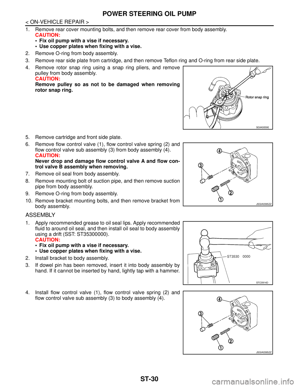
1. Remove rear cover mounting bolts, and then remove rear cover from body assembly.
CAUTION:
Fix oil pump with a vise if necessary.
Use copper plates when fixing with a vise.
2. Remove O-ring from body assembly.
3. Remove rear side plate from cartridge, and then remove Teflon ring and O-ring from rear side plate.
4. Remove rotor snap ring using a snap ring pliers, and remove
pulley from body assembly.
CAUTION:
Remove pulley so as not to be damaged when removing
rotor snap ring.
5. Remove cartridge and front side plate.
6. Remove flow control valve (1), flow control valve spring (2) and
flow control valve sub assembly (3) from body assembly (4).
CAUTION:
Never drop and damage flow control valve A and flow con-
trol valve B assembly when removing.
7. Remove oil seal from body assembly.
8. Remove mounting bolt of suction pipe, and then remove suction
pipe from body assembly.
9. Remove O-ring from body assembly.
10. Remove bracket mounting bolts, and then remove bracket from
body assembly.
ASSEMBLY
1. Apply recommended grease to oil seal lips. Apply recommended
fluid to around oil seal, and then install oil seal to body assembly
using a drift (SST: ST35300000).
CAUTION:
Fix oil pump with a vise if necessary.
Use copper plates when fixing with a vise.
2. Install bracket to body assembly.
3. If dowel pin has been removed, insert it into body assembly by
hand. If it cannot be inserted by hand, lightly tap with a hammer.
4. Install flow control valve (1), flow control valve spring (2) and
flow control valve sub assembly (3) to body assembly (4).
SGIA0059E
JSGIA0365ZZ
STC0914D
JSGIA0365ZZ