2008 NISSAN TEANA charging
[x] Cancel search: chargingPage 2594 of 5121
REFRIGERANT
HA-25
< ON-VEHICLE MAINTENANCE >
C
D
E
F
G
H
J
K
L
MA
B
HA
N
O
P
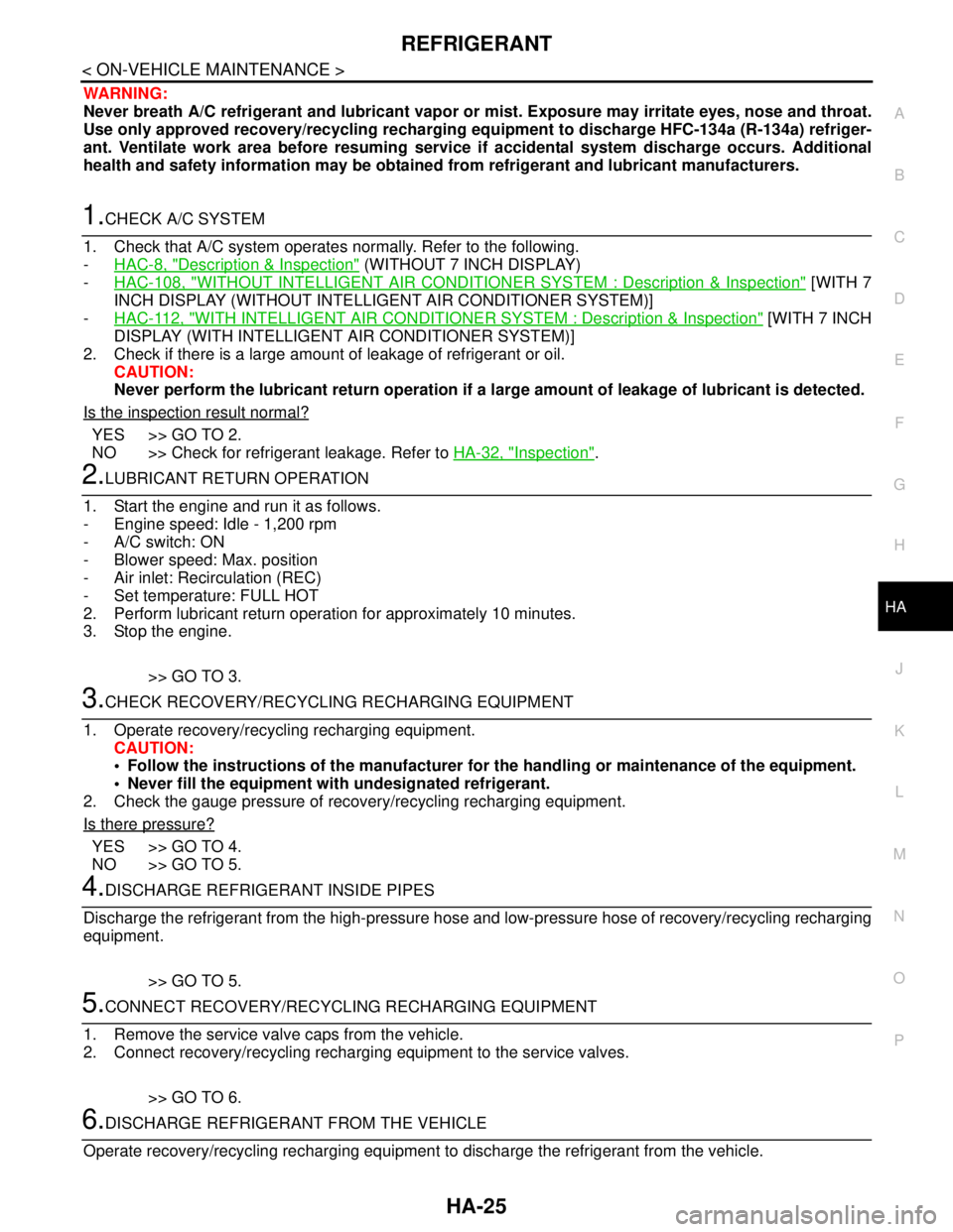
WARNING:
Never breath A/C refrigerant and lubricant vapor or mist. Exposure may irritate eyes, nose and throat.
Use only approved recovery/recycling recharging equipment to discharge HFC-134a (R-134a) refriger-
ant. Ventilate work area before resuming service if accidental system discharge occurs. Additional
health and safety information may be obtained from refrigerant and lubricant manufacturers.
1.CHECK A/C SYSTEM
1. Check that A/C system operates normally. Refer to the following.
-HAC-8, "
Description & Inspection" (WITHOUT 7 INCH DISPLAY)
-HAC-108, "
WITHOUT INTELLIGENT AIR CONDITIONER SYSTEM : Description & Inspection" [WITH 7
INCH DISPLAY (WITHOUT INTELLIGENT AIR CONDITIONER SYSTEM)]
-HAC-112, "
WITH INTELLIGENT AIR CONDITIONER SYSTEM : Description & Inspection" [WITH 7 INCH
DISPLAY (WITH INTELLIGENT AIR CONDITIONER SYSTEM)]
2. Check if there is a large amount of leakage of refrigerant or oil.
CAUTION:
Never perform the lubricant return operation if a large amount of leakage of lubricant is detected.
Is the inspection result normal?
YES >> GO TO 2.
NO >> Check for refrigerant leakage. Refer to HA-32, "
Inspection".
2.LUBRICANT RETURN OPERATION
1. Start the engine and run it as follows.
- Engine speed: Idle - 1,200 rpm
- A/C switch: ON
- Blower speed: Max. position
- Air inlet: Recirculation (REC)
- Set temperature: FULL HOT
2. Perform lubricant return operation for approximately 10 minutes.
3. Stop the engine.
>> GO TO 3.
3.CHECK RECOVERY/RECYCLING RECHARGING EQUIPMENT
1. Operate recovery/recycling recharging equipment.
CAUTION:
Follow the instructions of the manufacturer for the handling or maintenance of the equipment.
Never fill the equipment with undesignated refrigerant.
2. Check the gauge pressure of recovery/recycling recharging equipment.
Is there pressure?
YES >> GO TO 4.
NO >> GO TO 5.
4.DISCHARGE REFRIGERANT INSIDE PIPES
Discharge the refrigerant from the high-pressure hose and low-pressure hose of recovery/recycling recharging
equipment.
>> GO TO 5.
5.CONNECT RECOVERY/RECYCLING RECHARGING EQUIPMENT
1. Remove the service valve caps from the vehicle.
2. Connect recovery/recycling recharging equipment to the service valves.
>> GO TO 6.
6.DISCHARGE REFRIGERANT FROM THE VEHICLE
Operate recovery/recycling recharging equipment to discharge the refrigerant from the vehicle.
Page 2595 of 5121
HA-26
< ON-VEHICLE MAINTENANCE >
REFRIGERANT
>> GO TO 7.
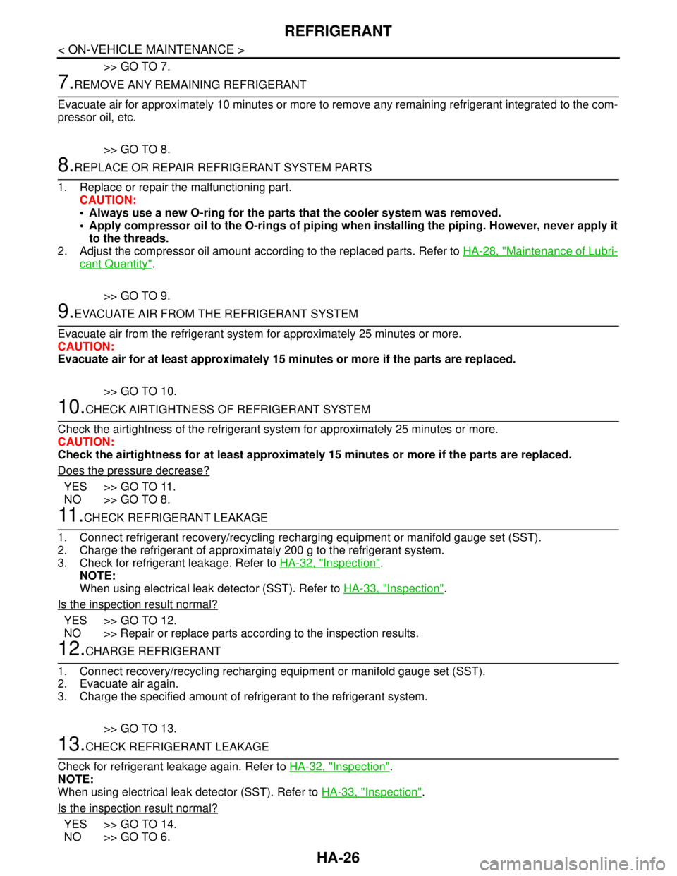
7.REMOVE ANY REMAINING REFRIGERANT
Evacuate air for approximately 10 minutes or more to remove any remaining refrigerant integrated to the com-
pressor oil, etc.
>> GO TO 8.
8.REPLACE OR REPAIR REFRIGERANT SYSTEM PARTS
1. Replace or repair the malfunctioning part.
CAUTION:
Always use a new O-ring for the parts that the cooler system was removed.
Apply compressor oil to the O-rings of piping when installing the piping. However, never apply it
to the threads.
2. Adjust the compressor oil amount according to the replaced parts. Refer to HA-28, "
Maintenance of Lubri-
cant Quantity".
>> GO TO 9.
9.EVACUATE AIR FROM THE REFRIGERANT SYSTEM
Evacuate air from the refrigerant system for approximately 25 minutes or more.
CAUTION:
Evacuate air for at least approximately 15 minutes or more if the parts are replaced.
>> GO TO 10.
10.CHECK AIRTIGHTNESS OF REFRIGERANT SYSTEM
Check the airtightness of the refrigerant system for approximately 25 minutes or more.
CAUTION:
Check the airtightness for at least approximately 15 minutes or more if the parts are replaced.
Does the pressure decrease?
YES >> GO TO 11.
NO >> GO TO 8.
11 .CHECK REFRIGERANT LEAKAGE
1. Connect refrigerant recovery/recycling recharging equipment or manifold gauge set (SST).
2. Charge the refrigerant of approximately 200 g to the refrigerant system.
3. Check for refrigerant leakage. Refer to HA-32, "
Inspection".
NOTE:
When using electrical leak detector (SST). Refer to HA-33, "
Inspection".
Is the inspection result normal?
YES >> GO TO 12.
NO >> Repair or replace parts according to the inspection results.
12.CHARGE REFRIGERANT
1. Connect recovery/recycling recharging equipment or manifold gauge set (SST).
2. Evacuate air again.
3. Charge the specified amount of refrigerant to the refrigerant system.
>> GO TO 13.
13.CHECK REFRIGERANT LEAKAGE
Check for refrigerant leakage again. Refer to HA-32, "
Inspection".
NOTE:
When using electrical leak detector (SST). Refer to HA-33, "
Inspection".
Is the inspection result normal?
YES >> GO TO 14.
NO >> GO TO 6.
Page 2596 of 5121

REFRIGERANT
HA-27
< ON-VEHICLE MAINTENANCE >
C
D
E
F
G
H
J
K
L
MA
B
HA
N
O
P
14.CHECK OPERATION
Check the A/C system for normal operation. Refer to HA-30, "
Inspection".
Is the inspection result normal?
YES >> GO TO 15.
NO >> Repair or replace parts according to the inspection results.
15.CHECK RECOVERY/RECYCLING RECHARGING EQUIPMENT
1. Disconnect recovery/recycling recharging equipment or manifold gauge set (SST).
2. Discharge the refrigerant from the high-pressure hose and low-pressure hose of the recovery/recycling
recharging equipment.
3. Install the service valve caps.
>> END
Page 2598 of 5121
LUBRICANT
HA-29
< ON-VEHICLE MAINTENANCE >
C
D
E
F
G
H
J
K
L
MA
B
HA
N
O
P
*: No addition of lubricant is needed if the refrigerant leakage is small.
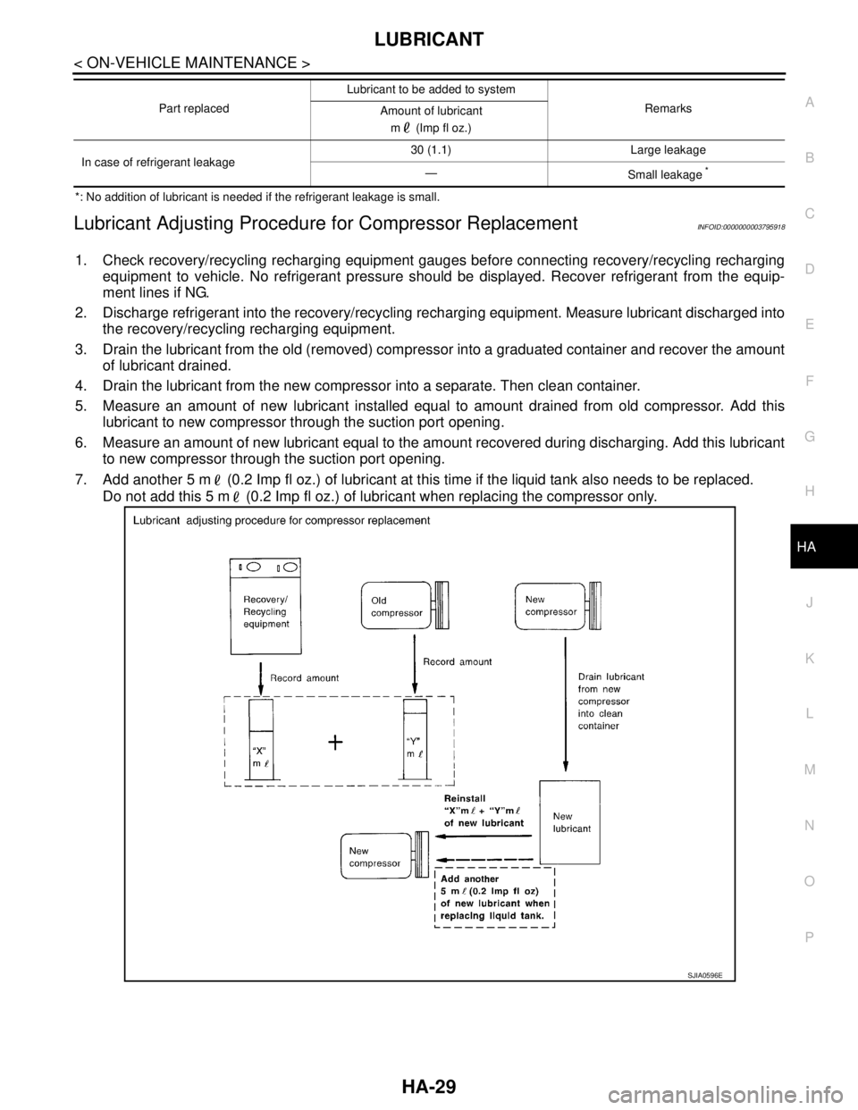
Lubricant Adjusting Procedure for Compressor ReplacementINFOID:0000000003795918
1. Check recovery/recycling recharging equipment gauges before connecting recovery/recycling recharging
equipment to vehicle. No refrigerant pressure should be displayed. Recover refrigerant from the equip-
ment lines if NG.
2. Discharge refrigerant into the recovery/recycling recharging equipment. Measure lubricant discharged into
the recovery/recycling recharging equipment.
3. Drain the lubricant from the old (removed) compressor into a graduated container and recover the amount
of lubricant drained.
4. Drain the lubricant from the new compressor into a separate. Then clean container.
5. Measure an amount of new lubricant installed equal to amount drained from old compressor. Add this
lubricant to new compressor through the suction port opening.
6. Measure an amount of new lubricant equal to the amount recovered during discharging. Add this lubricant
to new compressor through the suction port opening.
7. Add another 5 m (0.2 Imp fl oz.) of lubricant at this time if the liquid tank also needs to be replaced.
Do not add this 5 m (0.2 Imp fl oz.) of lubricant when replacing the compressor only.
In case of refrigerant leakage30 (1.1) Large leakage
—
Small leakage *
Part replacedLubricant to be added to system
Remarks
Amount of lubricant
m (Imp fl oz.)
SJIA0596E
Page 2599 of 5121
HA-30
< ON-VEHICLE MAINTENANCE >
REFRIGERATION SYSTEM
REFRIGERATION SYSTEM
InspectionINFOID:0000000003795977
1.CHECK BLOWER MOTOR OPERATION
Check blower motor operation. Refer to the following.
HAC-68, "
ComponentFunctionCheck" (WITHOUT 7 INCH DISPLAY)
HAC-193, "
ComponentFunctionCheck" (WITH 7 INCH DISPLAY)
Is the inspection result normal?
YES >> GO TO 2.
NO >> Repair or replace the parts according to the inspection results.
2.CHECK COMPRESSOR OPERATION
Check compressor operation. Refer to the following.
HAC-72, "
Component Function Check" (WITHOUT 7 INCH DISPLAY)
HAC-197, "
Component Function Check" (WITH 7 INCH DISPLAY)
Is the inspection result normal?
YES >> GO TO 3.
NO >> Repair or replace the parts according to the inspection results.
3.CHECK REFRIGERANT CYCLE PRESSURE
Connect recovery/recycling recharging equipment to the vehicle and perform the diagnosis with the gauge
pressure. Refer to HA-8, "
Trouble Diagnosis For Unusual Pressure".
Is the inspection result normal?
YES >> Perform the performance test. Refer to HA-30, "Performance Chart".
NO >> Repair or replace the parts according to the inspection results.
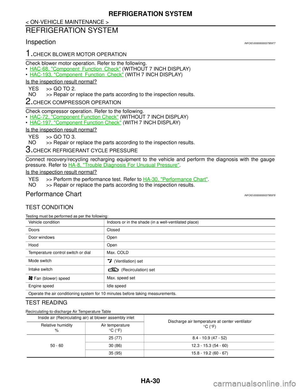
Performance ChartINFOID:0000000003795978
TEST CONDITION
Testing must be performed as per the following:
TEST READING
Recirculating-to-discharge Air Temperature Table
Vehicle condition Indoors or in the shade (in a well-ventilated place)
Doors Closed
Door windows Open
Hood Open
Temperature control switch or dial Max. COLD
Mode switch
(Ventilation) set
Intake switch
(Recirculation) set
Fan (blower) speedMax. speed set
Engine speed Idle speed
Operate the air conditioning system for 10 minutes before taking measurements.
Inside air (Recirculating air) at blower assembly inlet
Discharge air temperature at center ventilator
°C (°F) Relative humidity
%Air temperature
°C (°F)
50 - 6025 (77) 8.4 - 10.9 (47 - 52)
30 (86) 12.3 - 15.3 (54 - 60)
35 (95) 15.8 - 19.2 (60 - 67)
Page 2601 of 5121
HA-32
< ON-VEHICLE MAINTENANCE >
FLUORESCENT LEAK DETECTOR
FLUORESCENT LEAK DETECTOR
InspectionINFOID:0000000003795981
CHECKING SYSTEM FOR LEAKAGES USING THE FLUORESCENT LEAK DETECTOR
1. Check A/C system for leakages using the UV lamp and safety goggles (SST: J-42220) in a low sunlight
area (area without windows preferable). Illuminate all components, fittings and lines. The dye appears as
a bright green/yellow area at the point of leakage. Fluorescent dye observed at the evaporator drain open-
ing indicates an evaporator core assembly (tubes, core or expansion valve) leakage.
2. Use an adjustable mirror or wipe the area with a clean shop rag or cloth, with the UV lamp for dye residue
if the suspected area is difficult to see.
3. Remove any residual dye using dye cleaner (SST: J-43872) to prevent future misdiagnosis after the leak-
age is repaired.
4. Perform a system performance check and verify the leakage repair with an approved electrical leak detec-
tor.
NOTE:
Other gases in the work area or substances on the A/C components, for example, anti-freeze, windshield
washer fluid, solvents and lubricants, may falsely trigger the leak detector. Make sure the surfaces to be
checked are clean.
Clean with a dry cloth or blow off with shop air.
Do not allow the sensor tip of the detector to contact with any substance. This may also cause false readings
and may damage the detector.
DYE INJECTION
(This procedure is only necessary when recharging the system or when the compressor has seized and was
replaced.)
1. Check A/C system static (at rest) pressure. Pressure must be at least 345 kPa (3.45 bar, 3.52 kg/cm
2, 50
psi).
2. Pour one bottle (1/4 ounce / 7.4 cc) of the A/C refrigerant dye into the injector tool (SST: J-41459).
3. Connect the injector tool to the A/C low-pressure side service valve.
4. Start the engine. Then switch A/C ON.
5. Inject one bottle (1/4 ounce / 7.4 cc) of fluorescent dye through the low-pressure service valve using dye
injector tool (SST: J-41459) (refer to the manufacture’s operating instructions) when the A/C operating
(compressor running).
6. Disconnect the injector tool from the service valve with the engine still running.
CAUTION:
Be careful when replacing the A/C system or a component, pour the dye directly into the open sys-
tem connection and proceed with the service procedures.
7. Operate the A/C system for a minimum of 20 minutes to mix the dye with the system oil. Depending on the
leakage size, operating conditions and location of the leakage, it may take from minutes to days for the
dye to penetrate a leakage and become visible.
8. Attach a blue label if necessary.
Page 2604 of 5121
ELECTRICAL LEAK DETECTOR
HA-35
< ON-VEHICLE MAINTENANCE >
C
D
E
F
G
H
J
K
L
MA
B
HA
N
O
P
If no leakages are found, perform steps 7 - 10.
7. Start the engine.
8. Set the A/C control as per the following;
a. A/C switch: ON
b. Air flow: VENT (Ventilation)
c. Intake door position: Recirculation
d. Temperature setting: Max. cold
e. Fan speed: High
9. Run engine at 1,500 rpm for at least 2 minutes.
10. Stop the engine and perform leakage check again following
steps 4 through 6 above.
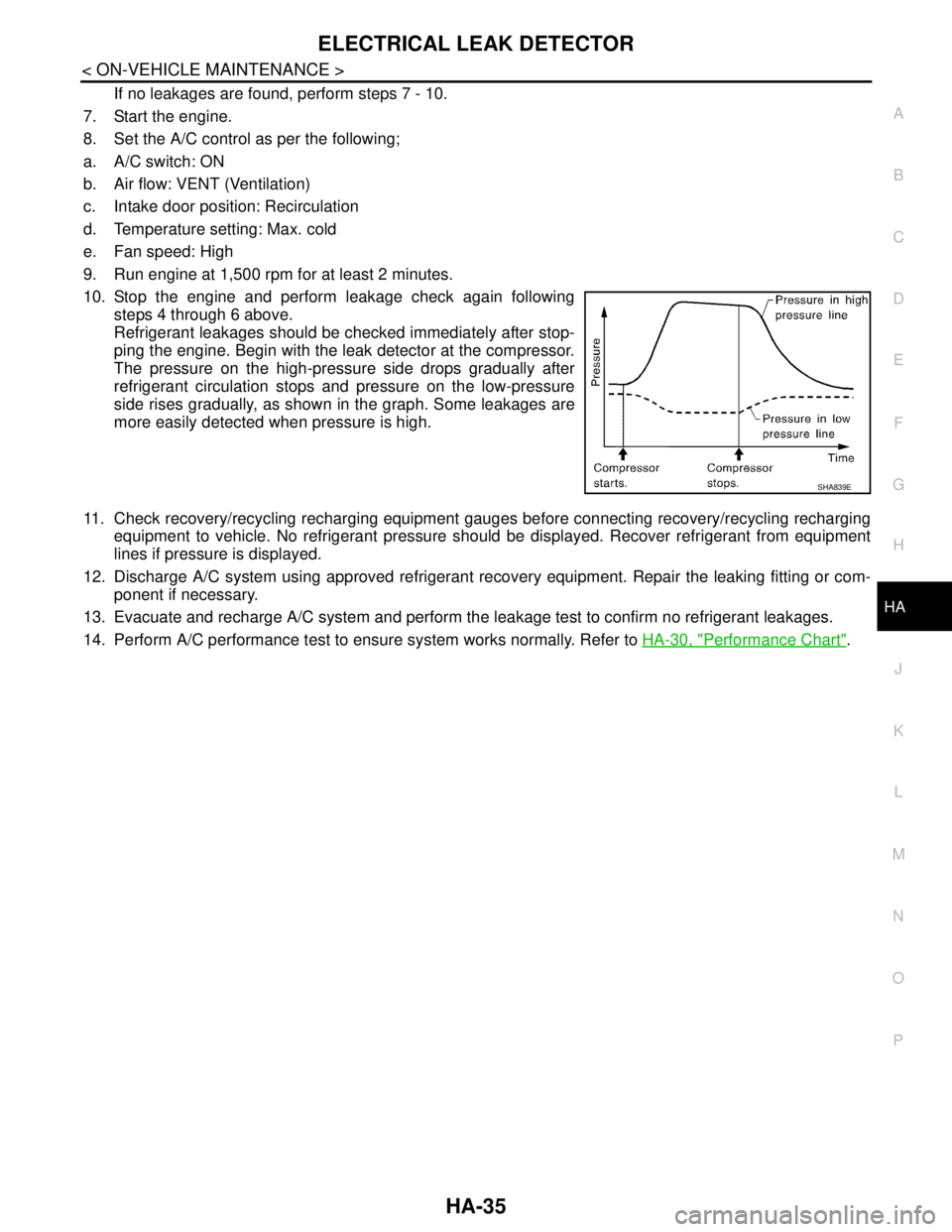
Refrigerant leakages should be checked immediately after stop-
ping the engine. Begin with the leak detector at the compressor.
The pressure on the high-pressure side drops gradually after
refrigerant circulation stops and pressure on the low-pressure
side rises gradually, as shown in the graph. Some leakages are
more easily detected when pressure is high.
11. Check recovery/recycling recharging equipment gauges before connecting recovery/recycling recharging
equipment to vehicle. No refrigerant pressure should be displayed. Recover refrigerant from equipment
lines if pressure is displayed.
12. Discharge A/C system using approved refrigerant recovery equipment. Repair the leaking fitting or com-
ponent if necessary.
13. Evacuate and recharge A/C system and perform the leakage test to confirm no refrigerant leakages.
14. Perform A/C performance test to ensure system works normally. Refer to HA-30, "
Performance Chart".
SHA839E
Page 2606 of 5121
COMPRESSOR
HA-37
< ON-VEHICLE REPAIR >
C
D
E
F
G
H
J
K
L
MA
B
HA
N
O
P
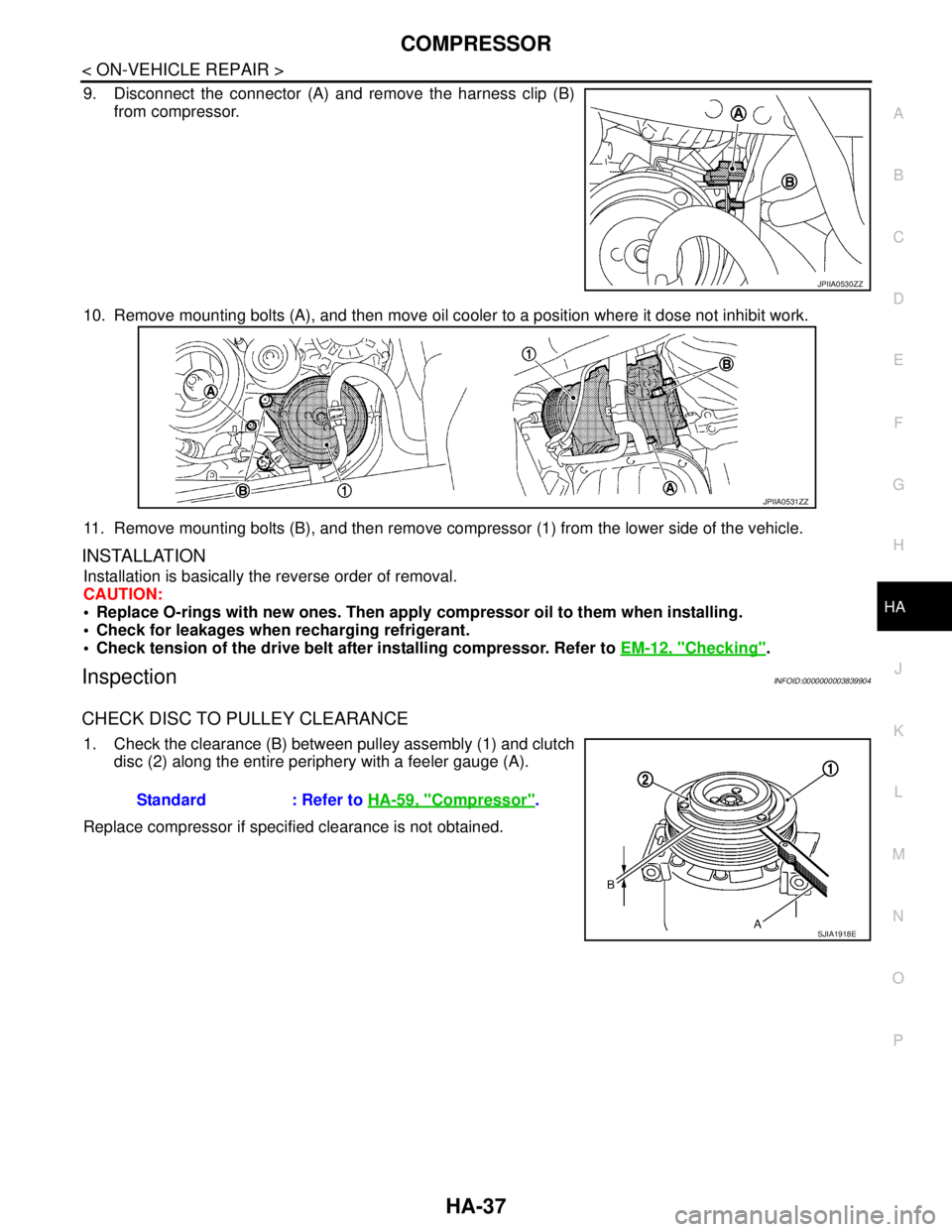
9. Disconnect the connector (A) and remove the harness clip (B)
from compressor.
10. Remove mounting bolts (A), and then move oil cooler to a position where it dose not inhibit work.
11. Remove mounting bolts (B), and then remove compressor (1) from the lower side of the vehicle.
INSTALLATION
Installation is basically the reverse order of removal.
CAUTION:
Replace O-rings with new ones. Then apply compressor oil to them when installing.
Check for leakages when recharging refrigerant.
Check tension of the drive belt after installing compressor. Refer to EM-12, "
Checking".
InspectionINFOID:0000000003839904
CHECK DISC TO PULLEY CLEARANCE
1. Check the clearance (B) between pulley assembly (1) and clutch
disc (2) along the entire periphery with a feeler gauge (A).
Replace compressor if specified clearance is not obtained.
JPIIA0530ZZ
JPIIA0531ZZ
Standard : Refer to HA-59, "Compressor".
SJIA1918ESJIA1918E