Page 1111 of 5121

CHG
S TERMINAL CIRCUIT
CHG-13
< COMPONENT DIAGNOSIS >
C
D
E
F
G
H
I
J
K
L B A
O
P N
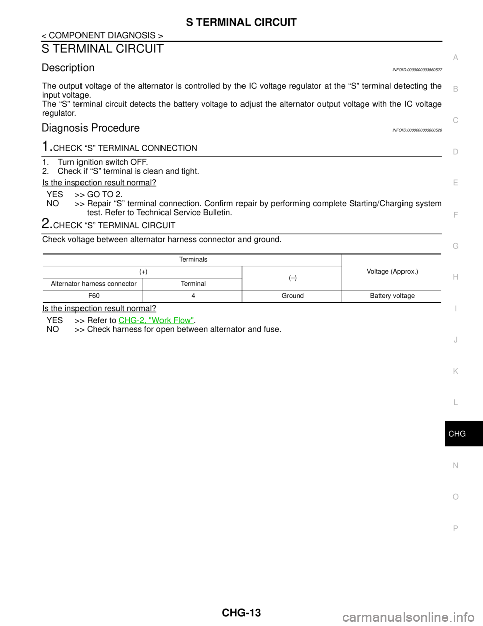
S TERMINAL CIRCUIT
DescriptionINFOID:0000000003860527
The output voltage of the alternator is controlled by the IC voltage regulator at the “S” terminal detecting the
input voltage.
The “S” terminal circuit detects the battery voltage to adjust the alternator output voltage with the IC voltage
regulator.
Diagnosis ProcedureINFOID:0000000003860528
1.CHECK “S” TERMINAL CONNECTION
1. Turn ignition switch OFF.
2. Check if “S” terminal is clean and tight.
Is the inspection result normal?
YES >> GO TO 2.
NO >> Repair “S” terminal connection. Confirm repair by performing complete Starting/Charging system
test. Refer to Technical Service Bulletin.
2.CHECK “S” TERMINAL CIRCUIT
Check voltage between alternator harness connector and ground.
Is the inspection result normal?
YES >> Refer to CHG-2, "Work Flow".
NO >> Check harness for open between alternator and fuse.
Te r m i n a l s
Voltage (Approx.) (+)
(–)
Alternator harness connector Terminal
F60 4 Ground Battery voltage
Page 1112 of 5121
CHG-14
< COMPONENT DIAGNOSIS >
CHARGING SYSTEM
CHARGING SYSTEM
Wiring Diagram - CHARGING SYSTEM -INFOID:0000000003860529
JCMWM1691GB
Page 1113 of 5121
CHG
CHARGING SYSTEM
CHG-15
< COMPONENT DIAGNOSIS >
C
D
E
F
G
H
I
J
K
L B A
O
P N
JCMWM1692GB
Page 1114 of 5121
CHG-16
< COMPONENT DIAGNOSIS >
CHARGING SYSTEM
JCMWM1693GB
Page 1115 of 5121
CHG
CHARGING SYSTEM
CHG-17
< SYMPTOM DIAGNOSIS >
C
D
E
F
G
H
I
J
K
L B A
O
P N
SYMPTOM DIAGNOSIS
CHARGING SYSTEM
Symptom TableINFOID:0000000003860530
Symptom Reference
Discharged battery
Refer to CHG-2, "
Work Flow". The charge warning lamp does not illuminate when the ignition
switch is set to ON.
The charge warning lamp does not turn OFF after the engine
starts.
The charge warning lamp turns ON when increasing the engine
speed.
Page 1118 of 5121

CHG-20
< ON-VEHICLE MAINTENANCE >
CHARGING SYSTEM PRELIMINARY INSPECTION
ON-VEHICLE MAINTENANCE
CHARGING SYSTEM PRELIMINARY INSPECTION
Inspection ProcedureINFOID:0000000003860533
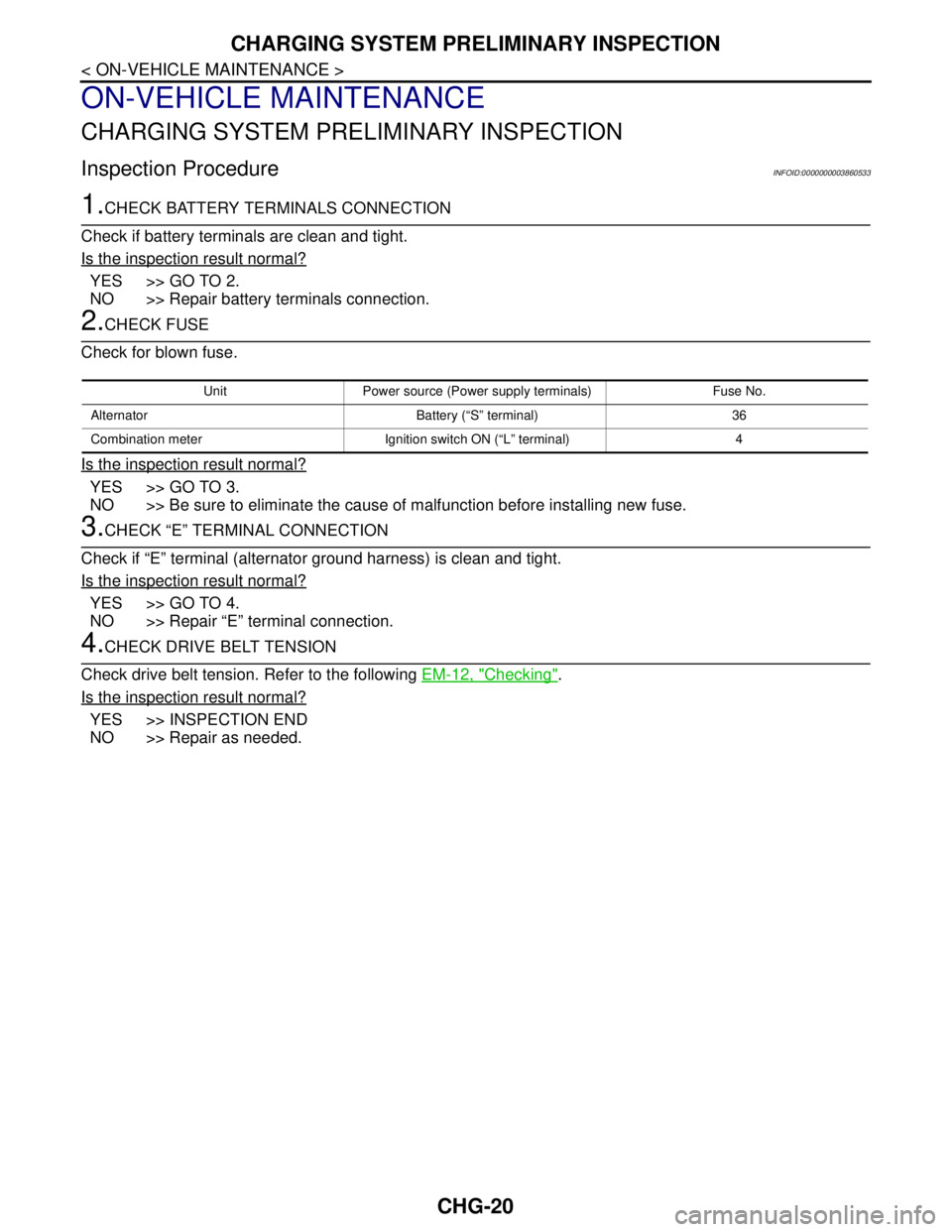
1.CHECK BATTERY TERMINALS CONNECTION
Check if battery terminals are clean and tight.
Is the inspection result normal?
YES >> GO TO 2.
NO >> Repair battery terminals connection.
2.CHECK FUSE
Check for blown fuse.
Is the inspection result normal?
YES >> GO TO 3.
NO >> Be sure to eliminate the cause of malfunction before installing new fuse.
3.CHECK “E” TERMINAL CONNECTION
Check if “E” terminal (alternator ground harness) is clean and tight.
Is the inspection result normal?
YES >> GO TO 4.
NO >> Repair “E” terminal connection.
4.CHECK DRIVE BELT TENSION
Check drive belt tension. Refer to the following EM-12, "
Checking".
Is the inspection result normal?
YES >> INSPECTION END
NO >> Repair as needed.
Unit Power source (Power supply terminals) Fuse No.
Alternator Battery (“S” terminal) 36
Combination meter Ignition switch ON (“L” terminal) 4
Page 1149 of 5121

CO-26
< ON-VEHICLE REPAIR >
WATER OUTLET AND WATER PIPING
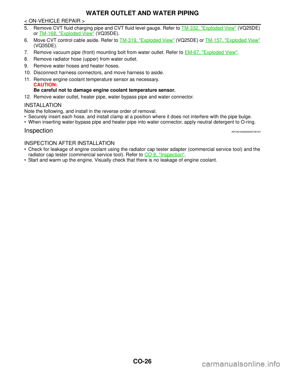
5. Remove CVT fluid charging pipe and CVT fluid level gauge. Refer to TM-332, "Exploded View" (VQ25DE)
or TM-168, "
Exploded View" (VQ35DE).
6. Move CVT control cable aside. Refer to TM-319, "
Exploded View" (VQ25DE) or TM-157, "Exploded View"
(VQ35DE).
7. Remove vacuum pipe (front) mounting bolt from water outlet. Refer to EM-67, "
Exploded View".
8. Remove radiator hose (upper) from water outlet.
9. Remove water hoses and heater hoses.
10. Disconnect harness connectors, and move harness to aside.
11. Remove engine coolant temperature sensor as necessary.
CAUTION:
Be careful not to damage engine coolant temperature sensor.
12. Remove water outlet, heater pipe, water bypass pipe and water connector.
INSTALLATION
Note the following, and install in the reverse order of removal.
Securely insert each hose, and install clamp at a position where it does not interfere with the pipe bulge.
When inserting water bypass pipe and heater pipe into water connector, apply neutral detergent to O-ring.
InspectionINFOID:0000000003793187
INSPECTION AFTER INSTALLATION
Check for leakage of engine coolant using the radiator cap tester adapter (commercial service tool) and the
radiator cap tester (commercial service tool). Refer to CO-8, "
Inspection".
Start and warm up the engine. Visually check that there is no leakage of engine coolant.
Page 1555 of 5121
![NISSAN TEANA 2008 Service Manual EC-94
< FUNCTION DIAGNOSIS >[VQ25DE, VQ35DE]
VARIABLE INDUCTION AIR SYSTEM
In the medium speed range, the power valves are closed. Under this condition, the pressure waves of the
exhaust stroke do not NISSAN TEANA 2008 Service Manual EC-94
< FUNCTION DIAGNOSIS >[VQ25DE, VQ35DE]
VARIABLE INDUCTION AIR SYSTEM
In the medium speed range, the power valves are closed. Under this condition, the pressure waves of the
exhaust stroke do not](/manual-img/5/57391/w960_57391-1554.png)
EC-94
< FUNCTION DIAGNOSIS >[VQ25DE, VQ35DE]
VARIABLE INDUCTION AIR SYSTEM
In the medium speed range, the power valves are closed. Under this condition, the pressure waves of the
exhaust stroke do not disturb the pressure waves of the intake stroke of each opposite bank. Therefore, charg-
ing efficiency is increased together with the effect of the long intake passage.
However, in the high speed range, the power valves are open. Under this condition, the pressure waves of
intake stroke are resonant with those of each opposite bank exhaust stroke. Therefore, charging efficiency is
also increased.
In addition, both valves (valves 1 and 2 for VQ35DE engine and a valve for VQ25DE engine) are opened or
closed in other ranges mentioned above. Thus maximum charging efficiency is obtained for the various driving
conditions.
VACUUM HOSE DRAWING (VQ35DE engine)
VACUUM HOSE DRAWING (VQ25DE engine)
1. Power valve actuator 1 2. VIAS control solenoid valve 1 3. VIAS control solenoid valve 2
4. Power valve actuator 2 5. Intake manifold collector
JMBIA0172ZZ