2008 NISSAN TEANA dimensions
[x] Cancel search: dimensionsPage 556 of 5121
![NISSAN TEANA 2008 Service Manual AV-412
< FUNCTION DIAGNOSIS >[BOSE AUDIO WITH NAVIGATION]
NAVIGATION SYSTEM
Map-matching does not function correctly when a road on which
the vehicle is driving is new and not recorded in the map DV NISSAN TEANA 2008 Service Manual AV-412
< FUNCTION DIAGNOSIS >[BOSE AUDIO WITH NAVIGATION]
NAVIGATION SYSTEM
Map-matching does not function correctly when a road on which
the vehicle is driving is new and not recorded in the map DV](/manual-img/5/57391/w960_57391-555.png)
AV-412
< FUNCTION DIAGNOSIS >[BOSE AUDIO WITH NAVIGATION]
NAVIGATION SYSTEM
Map-matching does not function correctly when a road on which
the vehicle is driving is new and not recorded in the map DVD-
ROM, or when road pattern stored in the map data and the actual
road pattern are different due to repair.
The map-matching function may find another road and position the
vehicle mark on it when driving on a road not present in the map.
Then, the vehicle mark may change to it when the correct road is
detected.
Effective range for comparing the vehicle position and travel direc-
tion calculated by the distance and direction with the road data
read from the map DVD-ROM is limited. Therefore, correction by
map-matching is not possible when there is an excessive gap
between current vehicle position and the position on the map.
GPS (GLOBAL POSITIONING SYSTEM)
GPS (Global Positioning System) was developed for and is con-
trolled by the US Department of Defense. The system utilizes GPS
satellites (NAVSTAR), sending out radio waves while flying on an
orbit around the earth at an altitude of approximately 21,000 km
(13,100miles).
The GPS receiver calculates the vehicle's position in three dimen-
sions (latitude/longitude/altitude) according to the time lag of the
radio waves received from four or more GPS satellites (three-dimen-
sional positioning). The GPS receiver calculates the vehicle's posi-
tion in two dimensions (latitude/longitude), utilizing the altitude data
calculated previously with radio waves from four or more GPS satel-
lites (two-dimensional positioning) if radio waves were received only
from three GPS satellites.
Position correction by GPS is not available while the vehicle is stopped.
Accuracy of GPS will deteriorate under the following conditions:
In two-dimensional positioning, GPS accuracy will deteriorate when altitude of the vehicle position changes.
The accuracy can be even lower depending on the arrangement of the GPS satellites utilized for the posi-
tioning.
Position detection is not possible when vehicle is in an area where radio waves from the GPS satellite do not
reach, such as in a tunnel, parking lot in a building, and under an elevated highway. Radio waves from the
GPS satellites may not be received when some object is located over the GPS antenna.
NOTE:
Even a high-precision three dimensional positioning, the detection result has an error about 10 m (30ft).
Because the signals of GPS satellite is controlled by the Tracking and Control Center in the United States,
the accuracy may be degraded lower intentionally or the radio waves may stop.
SKIA0613E
SEL526V
Page 1129 of 5121
CO-6
< PRECAUTION >
PRECAUTIONS
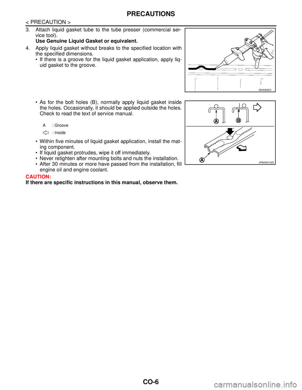
3. Attach liquid gasket tube to the tube presser (commercial ser-
vice tool).
Use Genuine Liquid Gasket or equivalent.
4. Apply liquid gasket without breaks to the specified location with
the specified dimensions.
If there is a groove for the liquid gasket application, apply liq-
uid gasket to the groove.
As for the bolt holes (B), normally apply liquid gasket inside
the holes. Occasionally, it should be applied outside the holes.
Check to read the text of service manual.
Within five minutes of liquid gasket application, install the mat-
ing component.
If liquid gasket protrudes, wipe it off immediately.
Never retighten after mounting bolts and nuts the installation.
After 30 minutes or more have passed from the installation, fill
engine oil and engine coolant.
CAUTION:
If there are specific instructions in this manual, observe them.
EMA0622D
A: Groove
: Inside
JPBIA0010ZZ
Page 1882 of 5121
PRECAUTIONS
EM-7
< PRECAUTION >
C
D
E
F
G
H
I
J
K
L
MA
EM
N
P O
Ensure thread and seat surfaces are clean and coated with engine oil.
Precaution for Liquid GasketINFOID:0000000003802233
REMOVAL OF LIQUID GASKET SEALING
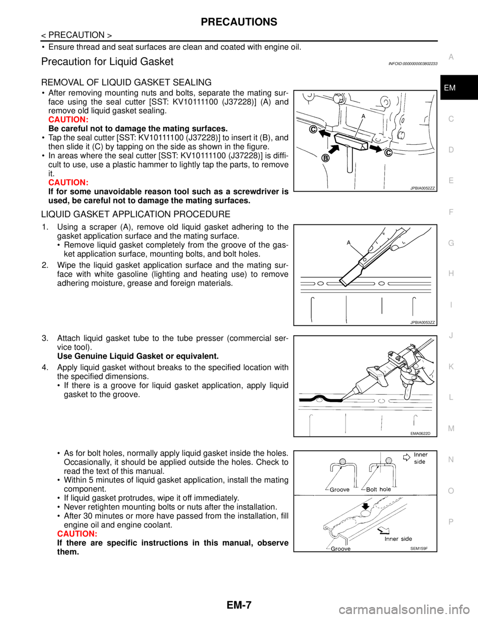
After removing mounting nuts and bolts, separate the mating sur-
f a c e u s i n g t h e s e a l c u t t e r [ S S T: K V 1 0 1111 0 0 ( J37228)] (A) and
remove old liquid gasket sealing.
CAUTION:
Be careful not to damage the mating surfaces.
Tap the seal cutter [SST: KV10111100 (J37228)] to insert it (B), and
then slide it (C) by tapping on the side as shown in the figure.
In areas where the seal cutter [SST: KV10111100 (J37228)] is diffi-
cult to use, use a plastic hammer to lightly tap the parts, to remove
it.
CAUTION:
If for some unavoidable reason tool such as a screwdriver is
used, be careful not to damage the mating surfaces.
LIQUID GASKET APPLICATION PROCEDURE
1. Using a scraper (A), remove old liquid gasket adhering to the
gasket application surface and the mating surface.
Remove liquid gasket completely from the groove of the gas-
ket application surface, mounting bolts, and bolt holes.
2. Wipe the liquid gasket application surface and the mating sur-
face with white gasoline (lighting and heating use) to remove
adhering moisture, grease and foreign materials.
3. Attach liquid gasket tube to the tube presser (commercial ser-
vice tool).
Use Genuine Liquid Gasket or equivalent.
4. Apply liquid gasket without breaks to the specified location with
the specified dimensions.
If there is a groove for liquid gasket application, apply liquid
gasket to the groove.
As for bolt holes, normally apply liquid gasket inside the holes.
Occasionally, it should be applied outside the holes. Check to
read the text of this manual.
Within 5 minutes of liquid gasket application, install the mating
component.
If liquid gasket protrudes, wipe it off immediately.
Never retighten mounting bolts or nuts after the installation.
After 30 minutes or more have passed from the installation, fill
engine oil and engine coolant.
CAUTION:
If there are specific instructions in this manual, observe
them.
JPBIA0052ZZ
JPBIA0053ZZ
EMA0622D
SEM159F
Page 1885 of 5121

EM-10
< PREPARATION >
PREPARATION
(—)
Manual lift table caddyRemoving and installing engine
(J24239-01)
Cylinder head bolt wrenchLoosening and tightening cylinder head bolt,
and used with the angle wrench [SST:
KV10112100 (BT8653-A)]
a: 13 mm (0.51 in) dia.
b: 12 mm (0.47 in)
c: 10 mm (0.39 in)
(—)
1.Compression tester
2.AdapterChecking compression pressure
(—)
Spark plug wrenchRemoving and installing spark plug
a: 14 mm (0.55 in)
(—)
Pulley holderRemoving and installing crankshaft pulley
(—)
Valve seat cutter setFinishing valve seat dimensions
(—)
Piston ring expanderRemoving and installing piston ring (SPX North America No.)
Tool nameDescription
ZZA1210D
NT583
ZZA0008D
JPBIA0399ZZ
ZZA1010D
NT048
NT030
Page 1976 of 5121
![NISSAN TEANA 2008 Service Manual CYLINDER HEAD
EM-101
< DISASSEMBLY AND ASSEMBLY >
C
D
E
F
G
H
I
J
K
L
MA
EM
N
P O
b. Drive out valve guide with a press [under a 20 kN (2 ton, 2.0 lmp
ton) pressure] or a hammer and the valve guide dr NISSAN TEANA 2008 Service Manual CYLINDER HEAD
EM-101
< DISASSEMBLY AND ASSEMBLY >
C
D
E
F
G
H
I
J
K
L
MA
EM
N
P O
b. Drive out valve guide with a press [under a 20 kN (2 ton, 2.0 lmp
ton) pressure] or a hammer and the valve guide dr](/manual-img/5/57391/w960_57391-1975.png)
CYLINDER HEAD
EM-101
< DISASSEMBLY AND ASSEMBLY >
C
D
E
F
G
H
I
J
K
L
MA
EM
N
P O
b. Drive out valve guide with a press [under a 20 kN (2 ton, 2.0 lmp
ton) pressure] or a hammer and the valve guide drift (commer-
cial service tool).
WARNING:
Cylinder head contains heat. When working, wear protec-
tive equipment to avoid getting burned.
9. Remove spark plug tube, as necessary.
Using a pliers, pull spark plug tube out of cylinder head.
CAUTION:
Take care not to damage cylinder head.
Once removed, spark plug tube will be deformed and cannot be reused. Never remove it unless
absolutely necessary.
ASSEMBLY
1. If valve guide is removed in step 8 (DISASSEMBLY), install it.
Replace with oversized [0.2 mm (0.008 in)] valve guide.
a. Using the valve guide reamer (commercial service tool) (A),
ream cylinder head valve guide hole.
b. Heat cylinder head to 110 to 130°C (230 to 266°F) by soaking in
heated oil (A).
c. Using the valve guide drift (commercial service tool), press valve
guide from camshaft side to the dimensions as in the figure.
WARNING:
Cylinder head contains heat. When working, wear protec-
tive equipment to avoid getting burned.
SEM931C
Valve guide hole diameter (for service parts):
Intake and exhaust
: Refer to EM-139, "
CylinderHead".
JPBIA0185ZZ
JPBIA0184ZZ
Projection (A)
Intake and exhaust
: Refer to EM-139, "
CylinderHead".
JPBIA0186ZZ
Page 1977 of 5121
EM-102
< DISASSEMBLY AND ASSEMBLY >
CYLINDER HEAD
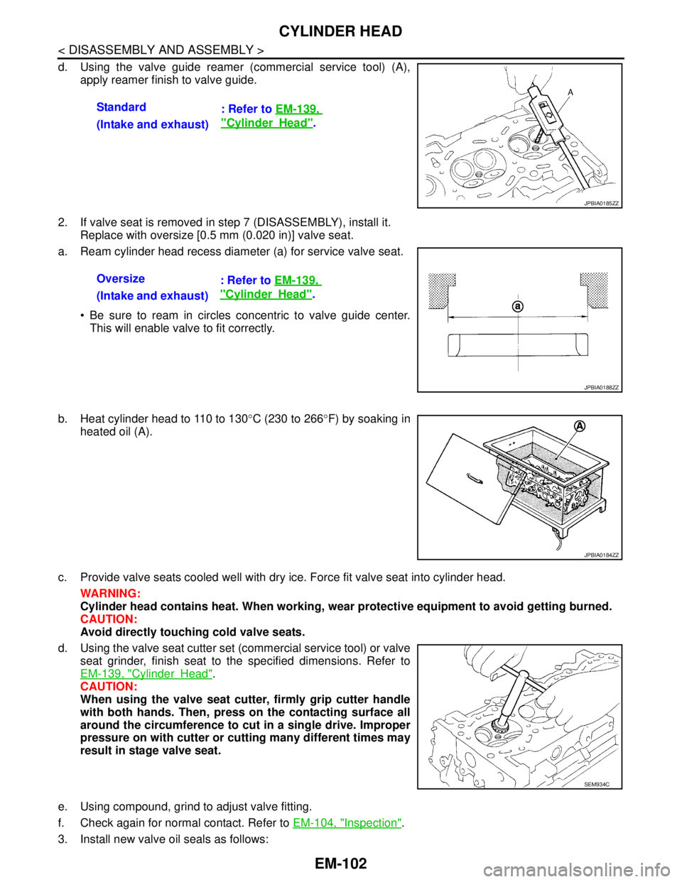
d. Using the valve guide reamer (commercial service tool) (A),
apply reamer finish to valve guide.
2. If valve seat is removed in step 7 (DISASSEMBLY), install it.
Replace with oversize [0.5 mm (0.020 in)] valve seat.
a. Ream cylinder head recess diameter (a) for service valve seat.
Be sure to ream in circles concentric to valve guide center.
This will enable valve to fit correctly.
b. Heat cylinder head to 110 to 130°C (230 to 266°F) by soaking in
heated oil (A).
c. Provide valve seats cooled well with dry ice. Force fit valve seat into cylinder head.
WARNING:
Cylinder head contains heat. When working, wear protective equipment to avoid getting burned.
CAUTION:
Avoid directly touching cold valve seats.
d. Using the valve seat cutter set (commercial service tool) or valve
seat grinder, finish seat to the specified dimensions. Refer to
EM-139, "
CylinderHead".
CAUTION:
When using the valve seat cutter, firmly grip cutter handle
with both hands. Then, press on the contacting surface all
around the circumference to cut in a single drive. Improper
pressure on with cutter or cutting many different times may
result in stage valve seat.
e. Using compound, grind to adjust valve fitting.
f. Check again for normal contact. Refer to EM-104, "
Inspection".
3. Install new valve oil seals as follows:Standard
: Refer to EM-139,
"CylinderHead".
(Intake and exhaust)
JPBIA0185ZZ
Oversize
: Refer to EM-139,
"CylinderHead".
(Intake and exhaust)
JPBIA0188ZZ
JPBIA0184ZZ
SEM934C
Page 1979 of 5121
EM-104
< DISASSEMBLY AND ASSEMBLY >
CYLINDER HEAD
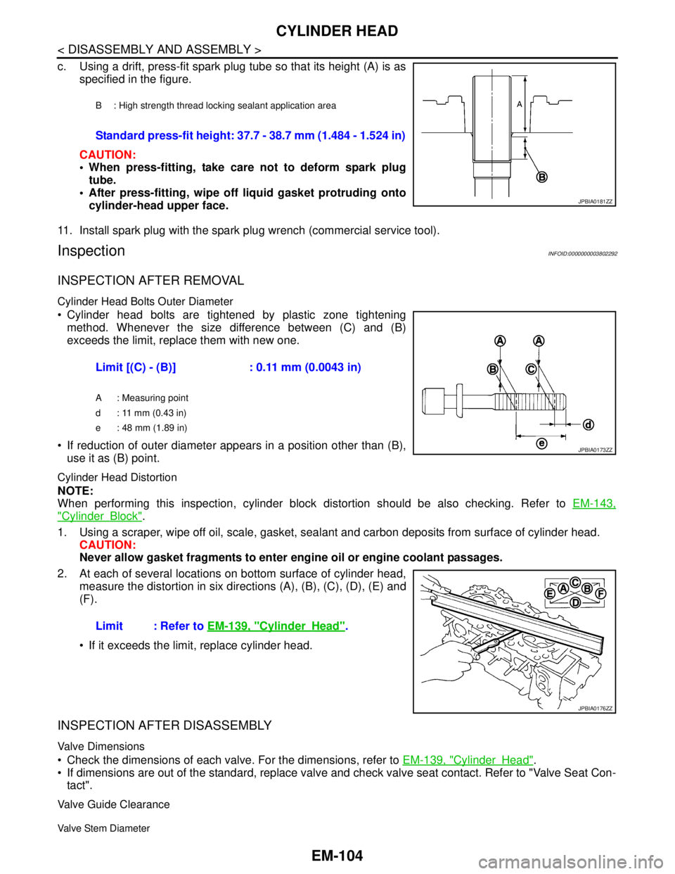
c. Using a drift, press-fit spark plug tube so that its height (A) is as
specified in the figure.
CAUTION:
When press-fitting, take care not to deform spark plug
tube.
After press-fitting, wipe off liquid gasket protruding onto
cylinder-head upper face.
11. Install spark plug with the spark plug wrench (commercial service tool).
InspectionINFOID:0000000003802292
INSPECTION AFTER REMOVAL
Cylinder Head Bolts Outer Diameter
Cylinder head bolts are tightened by plastic zone tightening
method. Whenever the size difference between (C) and (B)
exceeds the limit, replace them with new one.
If reduction of outer diameter appears in a position other than (B),
use it as (B) point.
Cylinder Head Distortion
NOTE:
When performing this inspection, cylinder block distortion should be also checking. Refer to EM-143,
"CylinderBlock".
1. Using a scraper, wipe off oil, scale, gasket, sealant and carbon deposits from surface of cylinder head.
CAUTION:
Never allow gasket fragments to enter engine oil or engine coolant passages.
2. At each of several locations on bottom surface of cylinder head,
measure the distortion in six directions (A), (B), (C), (D), (E) and
(F).
If it exceeds the limit, replace cylinder head.
INSPECTION AFTER DISASSEMBLY
Valve Dimensions
Check the dimensions of each valve. For the dimensions, refer to EM-139, "CylinderHead".
If dimensions are out of the standard, replace valve and check valve seat contact. Refer to "Valve Seat Con-
tact".
Valve Guide Clearance
Valve Stem Diameter
B : High strength thread locking sealant application area
Standard press-fit height: 37.7 - 38.7 mm (1.484 - 1.524 in)
JPBIA0181ZZ
Limit [(C) - (B)] : 0.11 mm (0.0043 in)
A : Measuring point
d : 11 mm (0.43 in)
e : 48 mm (1.89 in)
JPBIA0173ZZ
Limit : Refer to EM-139, "CylinderHead".
JPBIA0176ZZ
Page 1980 of 5121
CYLINDER HEAD
EM-105
< DISASSEMBLY AND ASSEMBLY >
C
D
E
F
G
H
I
J
K
L
MA
EM
N
P O
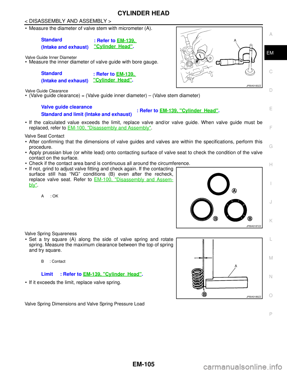
Measure the diameter of valve stem with micrometer (A).
Valve Guide Inner Diameter Measure the inner diameter of valve guide with bore gauge.
Valve Guide Clearance (Valve guide clearance) = (Valve guide inner diameter) – (Valve stem diameter)
If the calculated value exceeds the limit, replace valve and/or valve guide. When valve guide must be
replaced, refer to EM-100, "
Disassembly and Assembly".
Valve Seat Contact
After confirming that the dimensions of valve guides and valves are within the specifications, perform this
procedure.
Apply prussian blue (or white lead) onto contacting surface of valve seat to check the condition of the valve
contact on the surface.
Check if the contact area band is continuous all around the circumference.
If not, grind to adjust valve fitting and check again. If the contacting
surface still has “NG” conditions (B) even after the recheck,
replace valve seat. Refer to EM-100, "
Disassembly and Assem-
bly".
Valve Spring Squareness
Set a try square (A) along the side of valve spring and rotate
spring. Measure the maximum clearance between the top of spring
and try square.
If it exceeds the limit, replace valve spring.
Valve Spring Dimensions and Valve Spring Pressure Load
Standard
: Refer to EM-139,
"CylinderHead".
(Intake and exhaust)
Standard
: Refer to EM-139,
"CylinderHead".
(Intake and exhaust)
Valve guide clearance
: Refer to EM-139, "
CylinderHead".
Standard and limit (Intake and exhaust)
JPBIA0183ZZ
A: OK
JPBIA0187ZZ
B: Contact
Limit : Refer to EM-139, "CylinderHead".
JPBIA0189ZZ