2008 NISSAN TEANA fuse box
[x] Cancel search: fuse boxPage 2373 of 5121
![NISSAN TEANA 2008 Service Manual EXL-344
< ON-VEHICLE REPAIR >[HALOGEN TYPE]
FRONT COMBINATION LAMP
1. Remove the front bumper fascia. Refer to EXT-11, "Exploded View".
2. Remove the headlamp mounting bolts.
3. Remove the harness cli NISSAN TEANA 2008 Service Manual EXL-344
< ON-VEHICLE REPAIR >[HALOGEN TYPE]
FRONT COMBINATION LAMP
1. Remove the front bumper fascia. Refer to EXT-11, "Exploded View".
2. Remove the headlamp mounting bolts.
3. Remove the harness cli](/manual-img/5/57391/w960_57391-2372.png)
EXL-344
< ON-VEHICLE REPAIR >[HALOGEN TYPE]
FRONT COMBINATION LAMP
1. Remove the front bumper fascia. Refer to EXT-11, "Exploded View".
2. Remove the headlamp mounting bolts.
3. Remove the harness clips from the headlamp housing.
4. Pull out the headlamp assembly forward the vehicle.
5. Disconnect the connector before removing the headlamp assembly.
INSTALLATION
Install in the reverse order of removal.
NOTE:
After installation, perform aiming adjustment. Refer to EXL-336, "
Description".
ReplacementINFOID:0000000003773732
CAUTION:
Disconnect the battery negative terminal or remove the fuse.
After installing the bulb, install the resin cap and the bulb socket securely for watertightness.
Never touch the glass of bulb directly by hand. Keep grease and other oily matters away from it.
Never touch bulb by hand while it is lit or right after being turned off.
Never leave bulb out of lamp reflector for a long time because dust, moisture smoke, etc. may affect
the performance of lamp. When replacing bulb, be sure to replace it with new one.
HEADLAMP BULB (LO)
1. Remove the fender protector. Keep a service area. Refer to EXT-22, "FENDER PROTECTOR : Exploded
View".
2. Rotate the resin cap counterclockwise and unlock it.
3. Disconnect the headlamp bulb (LO) connector.
4. Rotate the bulb counterclockwise and unlock it.
5. Remove the bulb from the headlamp housing.
HEADLAMP BULB (HI)
1. Remove the fender protector. Keep a service area. Refer to EXT-22, "FENDER PROTECTOR : Exploded
View".
2. Disconnect the headlamp bulb (HI) connector.
3. Rotate the bulb counterclockwise and unlock it.
4. Remove the bulb from the headlamp housing.
PARKING LAMP BULB
1. Remove the fender protector. Keep a service area. Refer to EXT-22, "FENDER PROTECTOR : Exploded
View".
2. Rotate the parking lamp bulb socket counterclockwise and unlock it.
3. Remove the bulb from the parking lamp bulb socket.
FRONT TURN SIGNAL LAMP BULB
1. Remove the relay box cover*. Refer to PCS-34, "Exploded View".
*: When replace a left
2. Rotate the front turn signal lamp bulb socket counterclockwise and unlock it.
3. Remove the bulb from the front turn signal lamp bulb socket.
Disassembly and AssemblyINFOID:0000000003773733
DISASSEMBLY
1. Rotate the resin cap counterclockwise and unlock it
2. Disconnect the headlamp bulb (LO) connector.
3. Rotate the headlamp bulb (LO) counterclockwise and unlock it
4. Remove the bulb from the headlamp housing.
5. Rotate the headlamp bulb (HI) counterclockwise and unlock it
Page 2973 of 5121

INL-94
< ON-VEHICLE REPAIR >
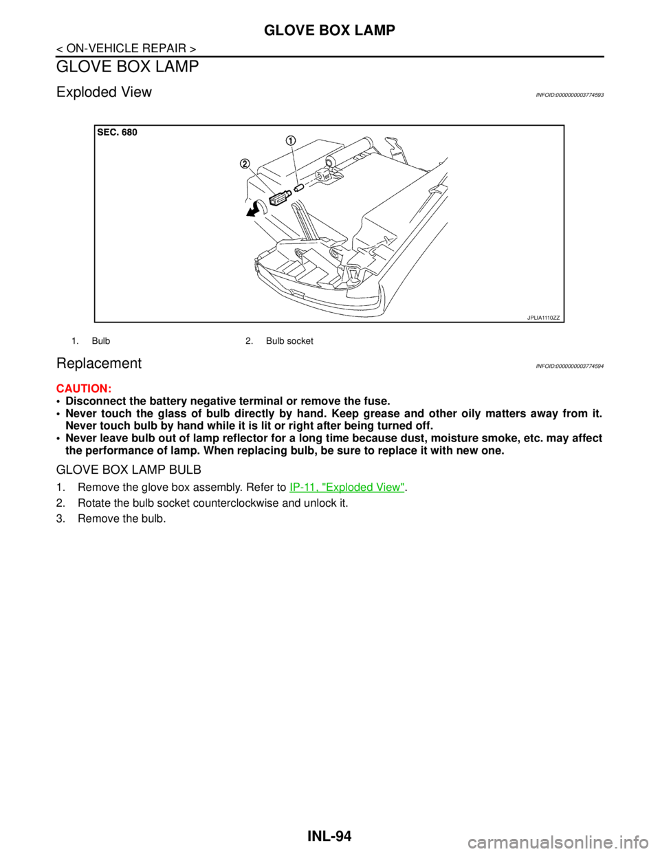
GLOVE BOX LAMP
GLOVE BOX LAMP
Exploded ViewINFOID:0000000003774593
ReplacementINFOID:0000000003774594
CAUTION:
Disconnect the battery negative terminal or remove the fuse.
Never touch the glass of bulb directly by hand. Keep grease and other oily matters away from it.
Never touch bulb by hand while it is lit or right after being turned off.
Never leave bulb out of lamp reflector for a long time because dust, moisture smoke, etc. may affect
the performance of lamp. When replacing bulb, be sure to replace it with new one.
GLOVE BOX LAMP BULB
1. Remove the glove box assembly. Refer to IP-11, "Exploded View".
2. Rotate the bulb socket counterclockwise and unlock it.
3. Remove the bulb.
1. Bulb 2. Bulb socket
J P L I A 111 0 Z Z
Page 3052 of 5121

IP-12
< ON-VEHICLE REPAIR >
INSTRUMENT PANEL ASSEMBLY
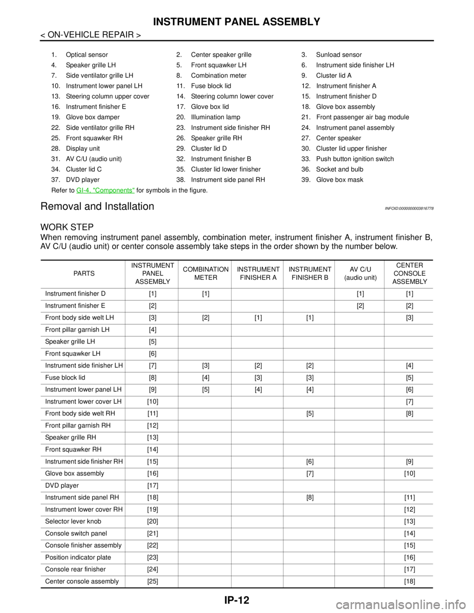
Removal and Installation
INFOID:0000000003816778
WORK STEP
When removing instrument panel assembly, combination meter, instrument finisher A, instrument finisher B,
AV C/U (audio unit) or center console assembly take steps in the order shown by the number below.
1. Optical sensor 2. Center speaker grille 3. Sunload sensor
4. Speaker grille LH 5. Front squawker LH 6. Instrument side finisher LH
7. Side ventilator grille LH 8. Combination meter 9. Cluster lid A
10. Instrument lower panel LH 11. Fuse block lid 12. Instrument finisher A
13. Steering column upper cover 14. Steering column lower cover 15. Instrument finisher D
16. Instrument finisher E 17. Glove box lid 18. Glove box assembly
19. Glove box damper 20. Illumination lamp 21. Front passenger air bag module
22. Side ventilator grille RH 23. Instrument side finisher RH 24. Instrument panel assembly
25. Front squawker RH 26. Speaker grille RH 27. Center speaker
28. Display unit 29. Cluster lid D 30. Cluster lid upper finisher
31. AV C/U (audio unit) 32. Instrument finisher B 33. Push button ignition switch
34. Cluster lid C 35. Cluster lid lower finisher 36. Socket and bulb
37. DVD player 38. Instrument side panel RH 39. Glove box mask
Refer to GI-4, "
Components" for symbols in the figure.
PA R T SINSTRUMENT
PA N E L
ASSEMBLYCOMBINATION
METERINSTRUMENT
FINISHER AINSTRUMENT
FINISHER BAV C / U
(audio unit)CENTER
CONSOLE
ASSEMBLY
Instrument finisher D [1] [1] [1] [1]
Instrument finisher E [2] [2] [2]
Front body side welt LH [3] [2] [1] [1] [3]
Front pillar garnish LH [4]
Speaker grille LH [5]
Front squawker LH [6]
Instrument side finisher LH [7] [3] [2] [2] [4]
Fuse block lid [8] [4] [3] [3] [5]
Instrument lower panel LH [9] [5] [4] [4] [6]
Instrument lower cover LH [10][7]
Front body side welt RH [11] [5] [8]
Front pillar garnish RH [12]
Speaker grille RH [13]
Front squawker RH [14]
Instrument side finisher RH [15] [6] [9]
Glove box assembly [16] [7] [10]
DVD player [17]
Instrument side panel RH [18] [8] [11]
Instrument lower cover RH [19][12]
Selector lever knob [20][13]
Console switch panel [21][14]
Console finisher assembly [22][15]
Position indicator plate [23][16]
Console rear finisher [24][17]
Center console assembly [25][18]
Page 3440 of 5121
![NISSAN TEANA 2008 Service Manual PCS
B2553 IGNITION RELAY
PCS-49
< COMPONENT DIAGNOSIS >[POWER DISTRIBUTION SYSTEM]
C
D
E
F
G
H
I
J
K
L B A
O
P N
B2553 IGNITION RELAY
DescriptionINFOID:0000000003805734
BCM turns ON the following rela NISSAN TEANA 2008 Service Manual PCS
B2553 IGNITION RELAY
PCS-49
< COMPONENT DIAGNOSIS >[POWER DISTRIBUTION SYSTEM]
C
D
E
F
G
H
I
J
K
L B A
O
P N
B2553 IGNITION RELAY
DescriptionINFOID:0000000003805734
BCM turns ON the following rela](/manual-img/5/57391/w960_57391-3439.png)
PCS
B2553 IGNITION RELAY
PCS-49
< COMPONENT DIAGNOSIS >[POWER DISTRIBUTION SYSTEM]
C
D
E
F
G
H
I
J
K
L B A
O
P N
B2553 IGNITION RELAY
DescriptionINFOID:0000000003805734
BCM turns ON the following relays to ignition power supply to each ECU when the ignition switch is turned
ON.
Ignition relay (inserted into fuse box)
Ignition relay (built into IPDM E/R)
Blower relay
BCM checks any ignition relay ON request for consistency with the actual ignition relay operation status.
DTC LogicINFOID:0000000003805735
DTC DETECTION LOGIC
DTC CONFIRMATION PROCEDURE
1.PERFORM DTC CONFIRMATION PROCEDURE
1. Turn ignition switch ON under the following conditions (start the engine), and wait for at least 2 seconds.
- Selector lever is in the P or N position.
- Do not depress brake pedal.
2. Check “Self diagnostic result” with CONSULT-III.
Is DTC detected?
YES >> Go to PCS-49, "Diagnosis Procedure".
NO >> INSPECTION END
Diagnosis ProcedureINFOID:0000000003805736
1.CHECK DTC WITH IPDM E/R
Check “Self diagnostic result” with CONSULT-III. Refer to PCS-120, "
DTCIndex".
Is the inspection result normal?
YES >> GO TO 2.
NO >> Repair or replace malfunctioning parts.
2.CHECK FUSE
Check that the following fuse is not fusing.
Is the fuse fusing?
YES >> Repair the applicable circuit. And then replace the fuse.
NO >> GO TO 3.
3.CHECK IGNITION RELAY FEEDBACK INPUT SIGNAL
1. Turn ignition switch OFF.
2. Disconnect BCM connector.
3. Check voltage between BCM harness connector and ground.
DTC No.Trouble diagnosis
nameDTC detecting condition Possible cause
B2553 IGNITION RELAYBCM detects a difference of signal for 2 seconds or
more between the following information.
Ignition relay (fuse block) ON/OFF operation
Ignition relay (fuse block) feedback. Harness or connectors
(ignition relay feedback circuit is
open or short)
Fuse
Ignition relay
IPDM E/R
Signal name Connection position Fuse No. Capacity
Ignition power supply FUSE BLOCK (J/B) 3 10A
Page 3519 of 5121

PG
PG-1
ELECTRICAL & POWER CONTROL
C
DE
F
G H
I
J
K L
B
SECTION PG
A
O P
N
CONTENTS
POWER SUPPLY, GROUND & CIRCUIT ELEMENTS
POWER SUPPLY&GR
OUND CIRCUIT
BASIC INSPECTION ....... .............................
3
BATTERY ....................................................... .....3
How to Handle Battery ........................................ ......3
Work Flow .................................................................5
COMPONENT DIAGNOSIS .........................10
POWER SUPPLY ROUTING CIRCUIT .......... ....10
Wiring Diagram - BATTERY POWER SUPPLY - ....10
Wiring Diagram - BATTERY POWER SUPPLY
FUSE No. 6 - ....................................................... ....
25
Wiring Diagram - BATTERY POWER SUPPLY
FUSE No. 11 - .........................................................
27
Wiring Diagram - BATTERY POWER SUPPLY
FUSE No. 31 - .........................................................
29
Wiring Diagram - BATTERY POWER SUPPLY
FUSE No. 50 - .........................................................
32
Wiring Diagram - BATTERY POWER SUPPLY
FUSE No. 52 - .........................................................
36
Wiring Diagram - BATTERY POWER SUPPLY
FUSE No. 53 - .........................................................
38
Wiring Diagram - ACCESSORY POWER SUP-
PLY - .......................................................................
48
Wiring Diagram - ACCESSORY POWER SUP-
PLY FUSE No. 19 - .................................................
51
Wiring Diagram - IGNITION POWER SUPPLY - ....55
Wiring Diagram - IGNITION POWER SUPPLY
FUSE No. 3 - ...........................................................
65
Wiring Diagram - IGNITION POWER SUPPLY
FUSE No. 4 - ...........................................................
74
Wiring Diagram - IGNITION POWER SUPPLY
FUSE No. 43 - .........................................................
77
Wiring Diagram - IGNITION POWER SUPPLY
FUSE No. 44 - .........................................................
79
Fuse ........................................................................82
Fusible Link .............................................................82
Circuit Breaker ........................................................82
HARNESS LAYOUT .........................................83
How To Read Harness Layout ............................ ....83
Outline .....................................................................84
Main Harness ..........................................................85
Engine Room Harness ............................................86
Engine Control Harness ..........................................88
Body Harness ..........................................................89
Body No. 2 Harness ................................................90
Room Lamp Harness ...............................................91
Front Door Harness (LH Side) .................................92
Front Door Harness (RH Side) ................................93
Rear Door Harness (LH Side) .................................94
Rear Door Harness (RH Side) .................................95
HARNESS CONNECTOR .................................96
Description ...............................................................96
STANDARDIZED RELAY .................................99
Description ...............................................................99
FUSE BLOCK - JUNCTION BOX (J/B) ..........101
Fuse, Connector and Terminal Arrangement ........101
FUSE, FUSIBLE LINK AND RELAY BOX ......102
Fuse and Fusible Link Arrangement ......................102
IPDM E/R (INTELLIGENT POWER DISTRI-
BUTION MODULE ENGINE ROOM) ..............
103
Fuse, Connector and Terminal Arrangement ........103
PRECAUTION ............................................104
PRECAUTIONS ...............................................104
Precaution for Supplemental Restraint System
(SRS) "AIR BAG" and "SEAT BELT PRE-TEN-
SIONER" ............................................................. ..
104
ON-VEHICLE MAINTENANCE ..................105
BATTERY CHARGING CHART ......................105
Slow Charge ........................................................ ..105
Standard Charge ...................................................106
Page 3619 of 5121
![NISSAN TEANA 2008 Service Manual PG
FUSE BLOCK - JUNCTION BOX (J/B)
PG-101
< COMPONENT DIAGNOSIS >[POWER SUPPLY&GROUND CIRCUIT]
C
D
E
F
G
H
I
J
K
L B A
O
P N
FUSE BLOCK - JUNCTION BOX (J/B)
Fuse, Connector and Terminal ArrangementINF NISSAN TEANA 2008 Service Manual PG
FUSE BLOCK - JUNCTION BOX (J/B)
PG-101
< COMPONENT DIAGNOSIS >[POWER SUPPLY&GROUND CIRCUIT]
C
D
E
F
G
H
I
J
K
L B A
O
P N
FUSE BLOCK - JUNCTION BOX (J/B)
Fuse, Connector and Terminal ArrangementINF](/manual-img/5/57391/w960_57391-3618.png)
PG
FUSE BLOCK - JUNCTION BOX (J/B)
PG-101
< COMPONENT DIAGNOSIS >[POWER SUPPLY&GROUND CIRCUIT]
C
D
E
F
G
H
I
J
K
L B A
O
P N
FUSE BLOCK - JUNCTION BOX (J/B)
Fuse, Connector and Terminal ArrangementINFOID:0000000003792684
JCMWM1766GB
Page 3620 of 5121
![NISSAN TEANA 2008 Service Manual PG-102
< COMPONENT DIAGNOSIS >[POWER SUPPLY&GROUND CIRCUIT]
FUSE, FUSIBLE LINK AND RELAY BOX
FUSE, FUSIBLE LINK AND RELAY BOX
Fuse and Fusible Link ArrangementINFOID:0000000003792685
JCMWM1767GB NISSAN TEANA 2008 Service Manual PG-102
< COMPONENT DIAGNOSIS >[POWER SUPPLY&GROUND CIRCUIT]
FUSE, FUSIBLE LINK AND RELAY BOX
FUSE, FUSIBLE LINK AND RELAY BOX
Fuse and Fusible Link ArrangementINFOID:0000000003792685
JCMWM1767GB](/manual-img/5/57391/w960_57391-3619.png)
PG-102
< COMPONENT DIAGNOSIS >[POWER SUPPLY&GROUND CIRCUIT]
FUSE, FUSIBLE LINK AND RELAY BOX
FUSE, FUSIBLE LINK AND RELAY BOX
Fuse and Fusible Link ArrangementINFOID:0000000003792685
JCMWM1767GB