2008 NISSAN TEANA maintenance schedule
[x] Cancel search: maintenance schedulePage 1472 of 5121
![NISSAN TEANA 2008 Service Manual INSPECTION AND ADJUSTMENT
EC-11
< BASIC INSPECTION >[VQ25DE, VQ35DE]
C
D
E
F
G
H
I
J
K
L
MA
EC
N
P O
INSPECTION AND ADJUSTMENT
BASIC INSPECTION
BASIC INSPECTION : Special Repair RequirementINFOID:0000 NISSAN TEANA 2008 Service Manual INSPECTION AND ADJUSTMENT
EC-11
< BASIC INSPECTION >[VQ25DE, VQ35DE]
C
D
E
F
G
H
I
J
K
L
MA
EC
N
P O
INSPECTION AND ADJUSTMENT
BASIC INSPECTION
BASIC INSPECTION : Special Repair RequirementINFOID:0000](/manual-img/5/57391/w960_57391-1471.png)
INSPECTION AND ADJUSTMENT
EC-11
< BASIC INSPECTION >[VQ25DE, VQ35DE]
C
D
E
F
G
H
I
J
K
L
MA
EC
N
P O
INSPECTION AND ADJUSTMENT
BASIC INSPECTION
BASIC INSPECTION : Special Repair RequirementINFOID:0000000003856444
1.INSPECTION START
1. Check service records for any recent repairs that may indicate a related malfunction, or a current need for
scheduled maintenance.
2. Open engine hood and check the following:
- Harness connectors for improper connections
- Wiring harness for improper connections, pinches and cut
- Vacuum hoses for splits, kinks and improper connections
- Hoses and ducts for leaks
- Air cleaner clogging
- Gasket
3. Confirm that electrical or mechanical loads are not applied.
- Head lamp switch is OFF.
- Air conditioner switch is OFF.
- Rear window defogger switch is OFF.
- Steering wheel is in the straight-ahead position, etc.
4. Start engine and warm it up until engine coolant temperature
indicator points the middle of gauge.
Ensure engine stays below 1,000 rpm.
5. Run engine at about 2,000 rpm for about 2 minutes under no
load.
6. Check that no DTC is displayed with CONSULT-III or GST.
Are any DTCs detected?
YES >> GO TO 2.
NO >> GO TO 3.
2.REPAIR OR REPLACE
Repair or replace components as necessary according to corresponding Diagnostic Procedure.
>> GO TO 3
3.CHECK TARGET IDLE SPEED
1. Run engine at about 2,000 rpm for about 2 minutes under no load.
SEF983U
SEF976U
SEF977U
Page 1564 of 5121
![NISSAN TEANA 2008 Service Manual ON BOARD DIAGNOSTIC (OBD) SYSTEM
EC-103
< FUNCTION DIAGNOSIS >[VQ25DE, VQ35DE]
C
D
E
F
G
H
I
J
K
L
MA
EC
N
P O
The 1st trip DTC (whose number is the same as the DTC number) is displayed for the latest NISSAN TEANA 2008 Service Manual ON BOARD DIAGNOSTIC (OBD) SYSTEM
EC-103
< FUNCTION DIAGNOSIS >[VQ25DE, VQ35DE]
C
D
E
F
G
H
I
J
K
L
MA
EC
N
P O
The 1st trip DTC (whose number is the same as the DTC number) is displayed for the latest](/manual-img/5/57391/w960_57391-1563.png)
ON BOARD DIAGNOSTIC (OBD) SYSTEM
EC-103
< FUNCTION DIAGNOSIS >[VQ25DE, VQ35DE]
C
D
E
F
G
H
I
J
K
L
MA
EC
N
P O
The 1st trip DTC (whose number is the same as the DTC number) is displayed for the latest self-diagnostic
result obtained. If the ECM memory was cleared previously, and the 1st trip DTC did not recur, the 1st trip DTC
will not be displayed.
If a malfunction is detected during the 1st trip, the 1st trip DTC is saved in the ECM memory. The MI will not
illuminate (two trip detection logic). If the same malfunction is not detected in the 2nd trip (meeting the required
driving pattern), the 1st trip DTC is cleared from the ECM memory. If the same malfunction is detected in the
2nd trip, both the 1st trip DTC and DTC are saved in the ECM memory and the MI illuminates. In other words,
the DTC is stored in the ECM memory and the MI illuminates when the same malfunction occurs in two con-
secutive trips. If a 1st trip DTC is stored and a non-diagnostic operation is performed between the 1st and 2nd
trips, only the 1st trip DTC will continue to be stored. For malfunctions that blink or illuminate the MI during the
1st trip, the DTC and 1st trip DTC are stored in the ECM memory.
Procedures for clearing the DTC and the 1st trip DTC from the ECM memory are described in “How to Erase
DTC and 1st Trip DTC”.
For malfunctions in which 1st trip DTCs are displayed, refer to “EMISSION-RELATED DIAGNOSTIC INFOR-
MATION ITEMS”. These items are required by legal regulations to continuously monitor the system/compo-
nent. In addition, the items monitored non-continuously are also displayed on CONSULT-III.
1st trip DTC is specified in Service $07 of ISO 15031-5. 1st trip DTC detection occurs without illuminating the
MI and therefore does not warn the driver of a malfunction. However, 1st trip DTC detection will not prevent
the vehicle from being tested, for example during Inspection/Maintenance (I/M) tests.
When a 1st trip DTC is detected, check, print out or write down and erase (1st trip) DTC and Freeze Frame
data as specified in Work Flow procedure Step 2, refer to EC-7, "
Work Flow". Then perform DTC Confirmation
Procedure or Component Function Check to try to duplicate the malfunction. If the malfunction is duplicated,
the item requires repair.
Freeze Frame Data and 1st Trip Freeze Frame Data
The ECM records the driving conditions such as fuel system status, calculated load value, engine coolant tem-
perature, short-term fuel trim, long-term fuel trim, engine speed, vehicle speed, absolute throttle position, base
fuel schedule and intake air temperature at the moment a malfunction is detected.
Data which are stored in the ECM memory, along with the 1st trip DTC, are called 1st trip freeze frame data.
The data, stored together with the DTC data, are called freeze frame data and displayed on CONSULT-III or
GST. The 1st trip freeze frame data can only be displayed on the CONSULT-III screen, not on the GST.
Only one set of freeze frame data (either 1st trip freeze frame data or freeze frame data) can be stored in the
ECM. 1st trip freeze frame data is stored in the ECM memory along with the 1st trip DTC. There is no priority
for 1st trip freeze frame data and it is updated each time a different 1st trip DTC is detected. However, once
freeze frame data (2nd trip detection/MI on) is stored in the ECM memory, 1st trip freeze frame data is no
longer stored. Remember, only one set of freeze frame data can be stored in the ECM. The ECM has the fol-
lowing priorities to update the data.
For example, the EGR malfunction (Priority: 2) was detected and the freeze frame data was saved in the 2nd
trip. After that when the misfire (Priority: 1) is detected in another trip, the freeze frame data will be updated
from the EGR malfunction to the misfire. The 1st trip freeze frame data is updated each time a different mal-
function is detected. There is no priority for 1st trip freeze frame data. However, once freeze frame data is
stored in the ECM memory, 1st trip freeze data is no longer stored (because only one freeze frame data or 1st
trip freeze frame data can be stored in the ECM). If freeze frame data is stored in the ECM memory and freeze
frame data with the same priority occurs later, the first (original) freeze frame data remains unchanged in the
ECM memory.
Both 1st trip freeze frame data and freeze frame data (along with the DTCs) are cleared when the ECM mem-
ory is erased. Procedures for clearing the ECM memory are described in “How to Erase DTC and 1st Trip
DTC”.
How to Read DTC and 1st Trip DTC
With CONSULT-III
With GST
CONSULT-III or GST (Generic Scan Tool) Examples: P0340, P0850, P1148, etc.
These DTCs are prescribed by ISO 15031-6.
Priority Items
1Freeze frame data Misfire — DTC: P0300 - P0306
Fuel Injection System Function — DTC: P0171, P0172, P0174, P0175
2 Except the above items (Includes CVT related items)
3 1st trip freeze frame data
Page 3194 of 5121

MA-6
< ON-VEHICLE MAINTENANCE >
PERIODIC MAINTENANCE
PERIODIC MAINTENANCE
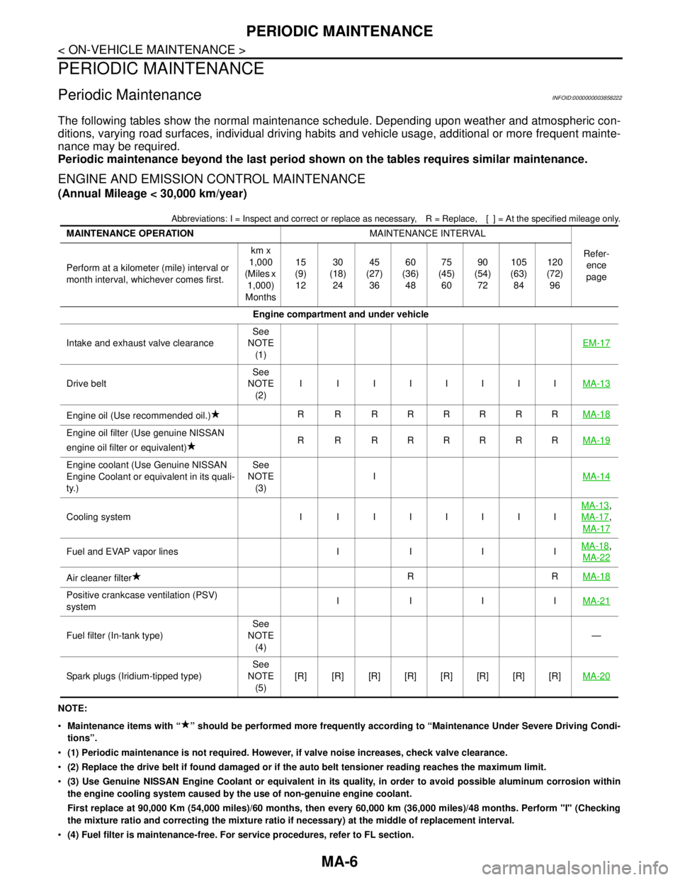
Periodic MaintenanceINFOID:0000000003858222
The following tables show the normal maintenance schedule. Depending upon weather and atmospheric con-
ditions, varying road surfaces, individual driving habits and vehicle usage, additional or more frequent mainte-
nance may be required.
Periodic maintenance beyond the last period shown on the tables requires similar maintenance.
ENGINE AND EMISSION CONTROL MAINTENANCE
(Annual Mileage < 30,000 km/year)
Abbreviations: I = Inspect and correct or replace as necessary, R = Replace,[ ] = At the specified mileage only.
NOTE:
Maintenance items with “ ” should be performed more frequently according to “Maintenance Under Severe Driving Condi-
tions”.
(1) Periodic maintenance is not required. However, if valve noise increases, check valve clearance.
(2) Replace the drive belt if found damaged or if the auto belt tensioner reading reaches the maximum limit.
(3) Use Genuine NISSAN Engine Coolant or equivalent in its quality, in order to avoid possible aluminum corrosion within
the engine cooling system caused by the use of non-genuine engine coolant.
First replace at 90,000 Km (54,000 miles)/60 months, then every 60,000 km (36,000 miles)/48 months. Perform "I" (Checking
the mixture ratio and correcting the mixture ratio if necessary) at the middle of replacement interval.
(4) Fuel filter is maintenance-free. For service procedures, refer to FL section. MAINTENANCE OPERATIONMAINTENANCE INTERVAL
Refer-
ence
page Perform at a kilometer (mile) interval or
month interval, whichever comes first.km x
1,000
(Miles x
1,000)
Months15
(9)
1230
(18)
2445
(27)
3660
(36)
4875
(45)
6090
(54)
72105
(63)
84120
(72)
96
Engine compartment and under vehicle
Intake and exhaust valve clearanceSee
NOTE
(1)EM-17
Drive beltSee
NOTE
(2)I I IIIIIIMA-13
Engine oil (Use recommended oil.)R R RRRRRRMA-18
Engine oil filter (Use genuine NISSAN
engine oil filter or equivalent)R R RRRRRRMA-19
Engine coolant (Use Genuine NISSAN
Engine Coolant or equivalent in its quali-
ty.)See
NOTE
(3)IMA-14
Cooling system I I IIIIIIMA-13
,
MA-17
,
MA-17
Fuel and EVAP vapor lines I I I IMA-18,
MA-22
Air cleaner filterRRMA-18
Positive crankcase ventilation (PSV)
systemIIIIMA-21
Fuel filter (In-tank type)See
NOTE
(4)—
Spark plugs (Iridium-tipped type)See
NOTE
(5)[R] [R] [R] [R] [R] [R] [R] [R]MA-20
Page 3225 of 5121

CHASSIS MAINTENANCE
MA-37
< ON-VEHICLE MAINTENANCE >
C
D
E
F
G
H
I
J
K
L
MB
MAN
OA
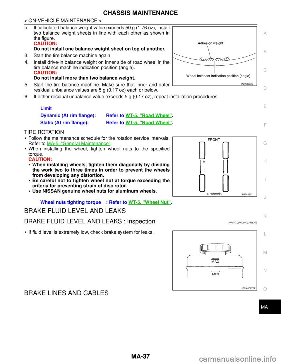
c. If calculated balance weight value exceeds 50 g (1.76 oz), install
two balance weight sheets in line with each other as shown in
the figure.
CAUTION:
Do not install one balance weight sheet on top of another.
3. Start the tire balance machine again.
4. Install drive-in balance weight on inner side of road wheel in the
tire balance machine indication position (angle).
CAUTION:
Do not install more than two balance weight.
5. Start the tire balance machine. Make sure that inner and outer
residual unbalance values are 5 g (0.17 oz) each or below.
6. If either residual unbalance value exceeds 5 g (0.17 oz), repeat installation procedures.
TIRE ROTATION
Follow the maintenance schedule for tire rotation service intervals.
Refer to MA-5, "
General Maintenance".
When installing the wheel, tighten wheel nuts to the specified
torque.
CAUTION:
When installing wheels, tighten them diagonally by dividing
the work two to three times in order to prevent the wheels
from developing any distortion.
Be careful not to tighten wheel nut at torque exceeding the
criteria for preventing strain of disc rotor.
Use NISSAN genuine wheel nuts for aluminum wheels.
BRAKE FLUID LEVEL AND LEAKS
BRAKE FLUID LEVEL AND LEAKS : InspectionINFOID:0000000003858309
If fluid level is extremely low, check brake system for leaks.
BRAKE LINES AND CABLES
Limit
Dynamic (At rim flange): Refer to WT-5, "
Road Wheel".
Static (At rim flange): Refer to WT-5, "
Road Wheel".
PEIA0033E
Wheel nuts tighting torque : Refer to WT-5, "Wheel Nut".
SMA829C
JPFIA0007ZZ
Page 4621 of 5121
![NISSAN TEANA 2008 Service Manual TM-148
< ON-VEHICLE MAINTENANCE >[CVT: RE0F09B]
ROAD TEST
ROAD TEST
DescriptionINFOID:0000000003849080
DESCRIPTION
The purpose of the test is to determine the overall performance of
CVT and analyze NISSAN TEANA 2008 Service Manual TM-148
< ON-VEHICLE MAINTENANCE >[CVT: RE0F09B]
ROAD TEST
ROAD TEST
DescriptionINFOID:0000000003849080
DESCRIPTION
The purpose of the test is to determine the overall performance of
CVT and analyze](/manual-img/5/57391/w960_57391-4620.png)
TM-148
< ON-VEHICLE MAINTENANCE >[CVT: RE0F09B]
ROAD TEST
ROAD TEST
DescriptionINFOID:0000000003849080
DESCRIPTION
The purpose of the test is to determine the overall performance of
CVT and analyze causes of problems.
The road test consists of the following three parts:
1. “Check Before Engine Is Started” TM-148
.
2. “Check at Idle” TM-149
.
3. “Cruise Test” TM-150
.
Before the road test, familiarize yourself with all test procedures
and items to check.
Perform tests for all the check items until a malfunction phenome-
non is detected. Perform diagnosis for NG items after the comple-
tion of road tests.
CONSULT-III SETTING PROCEDURE
Using CONSULT-III, perform a cruise test and record the result.
Print the result and ensure that shifts and lock-ups take place as per Shift Schedule.
1. Touch “Data Monitor” on “Direct Diagnostic Mode” screen.
2. Touch “MAIN SIGNALS” to set recording condition.
3. See “Numerical Display”, “Barchart Display” or “Line Graph Display”.
4. Touch “START”.
5. When performing cruise test. Refer to TM-150, "
Cruise Test".
6. After finishing cruise test part, touch “RECORD”.
7. Touch “STORE”.
8. Touch “BACK”.
9. Touch “DISPLAY”.
10. Touch “PRINT”.
11. Check the monitor data printed out.
Check before Engine Is StartedINFOID:0000000003849081
1.CHECK SPORT INDICATOR LAMP
1. Park vehicle on flat surface.
2. Move selector lever to “P” position.
3. Turn ignition switch OFF. Wait at least 5 seconds.
4. Turn ignition switch ON. (Do not start engine.)
Has SPORT indicator lamp been turned ON for about 2 seconds?
YES >> 1. Turn ignition switch OFF.
2. Perform self-diagnosis and note NG items. Refer to TM-121, "
DTC Index".
3. Go to TM-149, "
Check at Idle".
NO >> Stop “Road Test”. Refer to TM-123, "
Symptom Table".
SAT786A
SAT496G
Page 4783 of 5121
![NISSAN TEANA 2008 Service Manual TM-310
< ON-VEHICLE MAINTENANCE >[CVT: RE0F10A]
ROAD TEST
ROAD TEST
DescriptionINFOID:0000000003806508
DESCRIPTION
The purpose of the test is to determine the overall performance of
CVT and analyze NISSAN TEANA 2008 Service Manual TM-310
< ON-VEHICLE MAINTENANCE >[CVT: RE0F10A]
ROAD TEST
ROAD TEST
DescriptionINFOID:0000000003806508
DESCRIPTION
The purpose of the test is to determine the overall performance of
CVT and analyze](/manual-img/5/57391/w960_57391-4782.png)
TM-310
< ON-VEHICLE MAINTENANCE >[CVT: RE0F10A]
ROAD TEST
ROAD TEST
DescriptionINFOID:0000000003806508
DESCRIPTION
The purpose of the test is to determine the overall performance of
CVT and analyze causes of problems.
The road test consists of the following three parts:
1. “Check Before Engine Is Started” TM-310
.
2. “Check at Idle” TM-311
.
3. “Cruise Test” TM-312
.
Before the road test, familiarize yourself with all test procedures
and items to check.
Perform tests for all the check items until a malfunction phenome-
non is detected. Perform diagnosis for NG items after the comple-
tion of road tests.
CONSULT-III SETTING PROCEDURE
Using CONSULT-III, perform a cruise test and record the result.
Print the result and ensure that shifts and lock-ups take place as per Shift Schedule.
1. Touch “Data Monitor” on “Direct Diagnostic Mode” screen.
2. Touch “MAIN SIGNALS” to set recording condition.
3. See “Numerical Display”, “Barchart Display” or “Line Graph Display”.
4. Touch “START”.
5. When performing cruise test. Refer to TM-312, "
Cruise Test".
6. After finishing cruise test part, touch “RECORD”.
7. Touch “STORE”.
8. Touch “BACK”.
9. Touch “DISPLAY”.
10. Touch “PRINT”.
11. Check the monitor data printed out.
Check before Engine Is StartedINFOID:0000000003806509
1.CHECK SHIFT POSITION INDICATOR
1. Park vehicle on flat surface.
2. Move selector lever to “P” position.
3. Turn ignition switch OFF. Wait at least 5 seconds.
4. Turn ignition switch ON. (Never start engine.)
Has shift position indicator been turned ON for about 2 seconds?
YES >> 1. Turn ignition switch OFF.
2. Perform self-diagnosis and note NG items.
Refer to TM-204, "
CONSULT-III Function (TRANSMISSION)".
3. Go to TM-311, "
Check at Idle".
SAT786A
SAT496G
Page 5011 of 5121

WT-4
< ON-VEHICLE REPAIR >
ROAD WHEEL TIRE ASSEMBLY
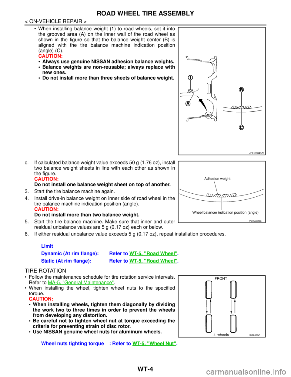
When installing balance weight (1) to road wheels, set it into
the grooved area (A) on the inner wall of the road wheel as
shown in the figure so that the balance weight center (B) is
aligned with the tire balance machine indication position
(angle) (C).
CAUTION:
Always use genuine NISSAN adhesion balance weights.
Balance weights are non-reusable; always replace with
new ones.
Do not install more than three sheets of balance weight.
c. If calculated balance weight value exceeds 50 g (1.76 oz), install
two balance weight sheets in line with each other as shown in
the figure.
CAUTION:
Do not install one balance weight sheet on top of another.
3. Start the tire balance machine again.
4. Install drive-in balance weight on inner side of road wheel in the
tire balance machine indication position (angle).
CAUTION:
Do not install more than two balance weight.
5. Start the tire balance machine. Make sure that inner and outer
residual unbalance values are 5 g (0.17 oz) each or below.
6. If either residual unbalance value exceeds 5 g (0.17 oz), repeat installation procedures.
TIRE ROTATION
Follow the maintenance schedule for tire rotation service intervals.
Refer to MA-5, "
General Maintenance".
When installing the wheel, tighten wheel nuts to the specified
torque.
CAUTION:
When installing wheels, tighten them diagonally by dividing
the work two to three times in order to prevent the wheels
from developing any distortion.
Be careful not to tighten wheel nut at torque exceeding the
criteria for preventing strain of disc rotor.
Use NISSAN genuine wheel nuts for aluminum wheels.
JPEIC0040ZZ
Limit
Dynamic (At rim flange): Refer to WT-5, "
Road Wheel".
Static (At rim flange): Refer to WT-5, "
Road Wheel".
PEIA0033E
Wheel nuts tighting torque : Refer to WT-5, "Wheel Nut".
SMA829C