2008 NISSAN TEANA air suspension
[x] Cancel search: air suspensionPage 1 of 5121

MODEL J32 SERIES
© 2008 NISSAN INTERNATIONAL SA
Allrightsreserved.NopartofthisElectronicServiceManualmaybereproducedorstoredinaretrievalsystem,ortransmittedinanyform,or by any means, electronic, mechanical, photocopying, recording or otherwise, without the prior written permission of Nissan InternationalSA, Switzerland.
AGENERALINFORMATION
BENGINE
DTRANSMISSION&DRIVELINE
ESUSPENSION
FBRAKES
GSTEERING
HRESTRAINTS
IVENTILATION,HEATER&AIRCONDITIONER
JBODYINTERIOR
KBODYEXTERIOR,DOOR,ROOF&VEHICLESECURITY
LDRIVERCONTROLS
MELECTRICAL&POWERCONTROL
NDRIVERINFORMATION&MULTIMEDIA
PMAINTENANCE
GIGeneralInformation
EMEngineMechanical
LUEngineLubricationSystem
COEngineCoolingSystem
ECEngineControlSystem
FLFuelSystem
EXExhaustSystem
STRStartingSystem
ACCAcceleratorControlSystem
TMTransaxle &Transmission
FAXFrontAxle
RAXRearAxle
FSUFrontSuspension
RSURearSuspension
WTRoadWheels &Tires
BRBrakeSystem
PBParkingBrakeSystem
BRCBrakeControlSystem
STSteeringSystem
STCSteeringControlSystem
SBSeatBelt
SRSRSAirbag
SRCSRSAirbagControlSystem
VTLVentilationSystem
HAHeater &AirConditioningSystem
HACHeater &AirConditioningControlSystem
INTInterior
IPInstrumentPanel
SESeat
ADPAutomaticDrivePositioner
DLKDoor &Lock
SECSecurityControlSystem
GWGlass &WindowSystem
PWCPowerWindowControlSystem
RFRoof
EXTExterior
MIRMirrors
EXLExteriorLightingSystem
INLInteriorLightingSystem
WWWiper &Washer
DEFDefogger
HRNHorn
PWOPowerOutlet
BCSBodyControlSystem
LANLANSystem
PCSPowerControlSystem
CHGChargingSystem
PGPowerSupply,Ground&CircuitElements
MWIMeter,WarningLamp&Indicator
WCSWarningChimeSystem
AVAudio,Visual&NavigationSystem
MAMaintenance
QUICKREFERENCEINDEX
A
B
C
D
E
F
G
H
I
J
K
L
M
N
O
P
M
Publication Number:
SM8E00-1J32E0E
Page 899 of 5121

NOISE, VIBRATION AND HARSHNESS (NVH) TROUBLESHOOTING
BR-3
< SYMPTOM DIAGNOSIS >
C
D
E
G
H
I
J
K
L
MA
B
BR
N
O
P
SYMPTOM DIAGNOSIS
NOISE, VIBRATION AND HARSHNESS (NVH) TROUBLESHOOTING
NVH Troubleshooting ChartINFOID:0000000003811166
Use the chart below to find the cause of the symptom. If necessary, repair or replace these parts.
×: ApplicableReference page
BR-13
, BR-15
BR-13
, BR-15
BR-34
, BR-40
BR-13
, BR-15
BR-13
, BR-15
BR-13
, BR-15
BR-13
, BR-15
BR-13
, BR-15
BR-13
, BR-15
BR-13
, BR-15
NVH in DLN section
NHV in DLN section
NVH in FAX, RAX, FSU and RSU section
NVH in WT section
NVH in WT section
NVH in FAX section
NVH in ST section
Possible cause and
SUSPECTED PARTS
Pads - damaged
Pads - uneven wear
Shims damaged
Rotor imbalance
Rotor damage
Rotor runout
Rotor deformation
Rotor deflection
Rotor rust
Rotor thickness variation
PROPELLER SHAFT
DIFFERENTIAL
AXLE AND SUSPENSION
TIRE
ROAD WHEEL
DRIVE SHAFT
STEERING
Symptom BRAKENoise××× ×× ×××
××
Shake×××××
××
Shimmy, Judder××××××× ××× ×
Page 1003 of 5121
![NISSAN TEANA 2008 Service Manual BRC-62
< BASIC INSPECTION >[VDC/TCS/ABS]
DIAGNOSIS AND REPAIR WORK FLOW
BASIC INSPECTION
DIAGNOSIS AND REPAIR WORK FLOW
Work FlowINFOID:0000000003766879
PRECAUTIONS FOR DIAGNOSIS
If steering angle sen NISSAN TEANA 2008 Service Manual BRC-62
< BASIC INSPECTION >[VDC/TCS/ABS]
DIAGNOSIS AND REPAIR WORK FLOW
BASIC INSPECTION
DIAGNOSIS AND REPAIR WORK FLOW
Work FlowINFOID:0000000003766879
PRECAUTIONS FOR DIAGNOSIS
If steering angle sen](/manual-img/5/57391/w960_57391-1002.png)
BRC-62
< BASIC INSPECTION >[VDC/TCS/ABS]
DIAGNOSIS AND REPAIR WORK FLOW
BASIC INSPECTION
DIAGNOSIS AND REPAIR WORK FLOW
Work FlowINFOID:0000000003766879
PRECAUTIONS FOR DIAGNOSIS
If steering angle sensor, steering system parts, suspension system parts, ABS actuator and electric unit (con-
trol unit) or tires have been replaced, or if wheel alignment has been adjusted, be sure to adjust neutral posi-
tion of steering angle sensor before driving. Refer to BRC-66, "
ADJUSTMENT OF STEERING ANGLE
SENSOR NEUTRAL POSITION : Description".
Page 1007 of 5121
![NISSAN TEANA 2008 Service Manual BRC-66
< BASIC INSPECTION >[VDC/TCS/ABS]
INSPECTION AND ADJUSTMENT
INSPECTION AND ADJUSTMENT
ADDITIONAL SERVICE WHEN REPLACING CONTROL UNIT
ADDITIONAL SERVICE WHEN REPLACING CONTROL UNIT : Description NISSAN TEANA 2008 Service Manual BRC-66
< BASIC INSPECTION >[VDC/TCS/ABS]
INSPECTION AND ADJUSTMENT
INSPECTION AND ADJUSTMENT
ADDITIONAL SERVICE WHEN REPLACING CONTROL UNIT
ADDITIONAL SERVICE WHEN REPLACING CONTROL UNIT : Description](/manual-img/5/57391/w960_57391-1006.png)
BRC-66
< BASIC INSPECTION >[VDC/TCS/ABS]
INSPECTION AND ADJUSTMENT
INSPECTION AND ADJUSTMENT
ADDITIONAL SERVICE WHEN REPLACING CONTROL UNIT
ADDITIONAL SERVICE WHEN REPLACING CONTROL UNIT : Description
INFOID:0000000003766881
After replacing the ABS actuator and electric unit (control unit), perform the neutral position adjustment for the
steering angle sensor.
ADDITIONAL SERVICE WHEN REPLACING CONTROL UNIT : Special Repair Re-
quirement
INFOID:0000000003766882
1.PERFORM THE NEUTRAL POSITION ADJUSTMENT FOR THE STEERING ANGLE SENSOR
Perform the neutral position adjustment for the steering angle sensor.
>> Refer to BRC-66, "
ADJUSTMENT OF STEERING ANGLE SENSOR NEUTRAL POSITION : Spe-
cial Repair Requirement".
ADJUSTMENT OF STEERING ANGLE SENSOR NEUTRAL POSITION
ADJUSTMENT OF STEERING ANGLE SENSOR NEUTRAL POSITION : Description
INFOID:0000000003766883
When doing work that applies to the list below, make sure to adjust neutral position of steering angle sensor
before running vehicle.
×: Required –: Not required
ADJUSTMENT OF STEERING ANGLE SENSOR NEUTRAL POSITION : Special Re-
pair Requirement
INFOID:0000000003766884
ADJUSTMENT OF STEERING ANGLE SENSOR NEUTRAL POSITION
CAUTION:
To adjust neutral position of steering angle sensor, make sure to use CONSULT-III.
(Adjustment cannot be done without CONSULT-III.)
1.ALIGN THE VEHICLE STATUS
Stop the vehicle with front wheels in straight-ahead position.
>> GO TO 2.
2.PERFORM THE NEUTRAL POSITION ADJUSTMENT FOR THE STEERING ANGLE SENSOR
1. On the CONSULT-III screen, touch "WORK SUPPORT" and “ST ANG SEN ADJUSTMENT" in order.
2. Touch “START”.
Situation Adjustment of steering angle sensor neutral position
Removing/Installing ABS actuator and electric unit (control unit) —
Replacing ABS actuator and electric unit (control unit)×
Removing/Installing steering angle sensor×
Replacing steering angle sensor×
Removing/Installing steering components×
Replacing steering components×
Removing/Installing suspension components×
Replacing suspension components×
Change tires to new ones—
Tire rotation—
Adjusting wheel alignment×
Page 1091 of 5121
![NISSAN TEANA 2008 Service Manual BRC-150
< PRECAUTION >[VDC/TCS/ABS]
PRECAUTIONS
Precaution for Brake Control
INFOID:0000000003767032
When starting engine or when starting vehicle just after starting engine, brake pedal may vibrate NISSAN TEANA 2008 Service Manual BRC-150
< PRECAUTION >[VDC/TCS/ABS]
PRECAUTIONS
Precaution for Brake Control
INFOID:0000000003767032
When starting engine or when starting vehicle just after starting engine, brake pedal may vibrate](/manual-img/5/57391/w960_57391-1090.png)
BRC-150
< PRECAUTION >[VDC/TCS/ABS]
PRECAUTIONS
Precaution for Brake Control
INFOID:0000000003767032
When starting engine or when starting vehicle just after starting engine, brake pedal may vibrate or motor
operating noise may be heard from engine compartment. This is normal condition.
When an error is indicated by ABS or another warning lamp, collect all necessary information from customer
(what symptoms are present under what conditions) and check for estimate causes before starting diagnos-
tic servicing. Besides electrical system inspection, check brake booster operation, brake fluid level, and oil
leaks.
If tire size and type are used in an improper combination, or brake pads are not Genuine NISSAN parts,
stopping distance or steering stability may deteriorate.
ABS might be out of order or malfunctions by putting a radio (wiring inclusive), an antenna and a lead-in wire
near the control unit.
If aftermarket parts (car stereo, CD player, etc.) have been installed, check for incidents such as harness
pinches, open circuits, and improper wiring.
VDC system may not operate normally or a VDC OFF indicator lamp or SLIP indicator lamp may light.
- When replacing the following parts with parts other than genuine parts or making modifications: Suspension
related parts (shock absorber, spring, bushing, etc.), tires, wheels (other than specified sizes), brake-related
parts (pad, rotor, caliper, etc.), engine-related parts (muffler, ECM, etc.) and body reinforcement-related parts
(roll bar, tower bar, etc.).
- When driving with worn or deteriorated suspension, tires and brake-related parts.
Precautions for Harness RepairINFOID:0000000003843440
COMMUNICATION LINE
Solder the repaired area and wrap tape around the soldered area.
NOTE:
A fray of twisted lines must be within 110 mm (4.33 in).
Bypass connection is never allowed at the repaired area.
NOTE:
Bypass connection may cause communication error as spliced
wires that are separate from the main line or twisted lines lose
noise immunity.
Replace the applicable harness as an assembly if error is detected
on the shield lines of communication line.
SKIB8766E
SKIB8767E
Page 1914 of 5121

OIL PAN AND OIL STRAINER
EM-39
< ON-VEHICLE REPAIR >
C
D
E
F
G
H
I
J
K
L
MA
EM
N
P O
Splash guard (RH and LH): Refer to EXT-22, "FENDER PROTECTOR : Exploded View".
Exhaust front tube: Refer to EX-5, "
Exploded View".
Drive belt: Refer to EM-12, "
Removal and Installation".
4. Remove A/C compressor with piping connected, and temporarily secure it to aside. Refer to HA-36,
"Exploded View".
5. Remove oil level gauge. Refer to EM-96, "
Exploded View".
6. Remove front drive shaft (RH). Refer to FAX-16, "
Exploded View".
7. Remove three way catalyst (bank 1 and bank 2) from exhaust manifolds (bank 1 and bank 2). Refer to
EM-34, "
Exploded View".
8. Remove oil pressure switch.
9. Remove oil filter. Refer to LU-10, "
Removal and Installation".
10. Remove oil cooler and water pipes. Refer to LU-11, "
Exploded View".
11. Support transaxle assembly with a suitable jack.
CAUTION:
When setting the transmission jack, be careful not to allow it to collide against the drain plug.
12. Support front suspension member with a suitable jack.
13. Remove engine mounting insulator (rear). Refer to EM-67, "
Exploded View".
14. Remove engine mounting insulator (LH) mounting bolts from transaxle. Refer to EM-67, "
Exploded View".
15. Remove rear torque rod through bolts from rear torque rod bracket. Refer to EM-67, "
Exploded View".
16. Remove member stay, front suspension member fixing bolts and nuts. Refer to FSU-16, "
Exploded View".
17. Lower the jack for the front suspension member to the height.
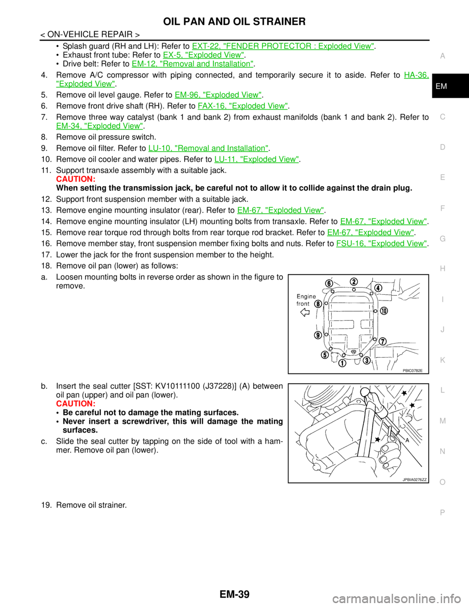
18. Remove oil pan (lower) as follows:
a. Loosen mounting bolts in reverse order as shown in the figure to
remove.
b. Insert the seal cutter [SST: KV10111100 (J37228)] (A) between
oil pan (upper) and oil pan (lower).
CAUTION:
Be careful not to damage the mating surfaces.
Never insert a screwdriver, this will damage the mating
surfaces.
c. Slide the seal cutter by tapping on the side of tool with a ham-
mer. Remove oil pan (lower).
19. Remove oil strainer.
PBIC0782E
JPBIA0276ZZ
Page 1943 of 5121

EM-68
< REMOVAL AND INSTALLATION >
ENGINE ASSEMBLY
Place chocks at front and back of rear wheels.
For engines not equipped with engine slingers, attach proper slingers and bolts described in PARTS
CATALOG.
CAUTION:
Always be careful to work safely, avoid forceful or uninstructed operations.
Never start working until exhaust system and engine coolant are cool enough.
If items or work required are not covered by the engine section, refer to the applicable sections.
Always use the support point specified for lifting.
Use either 2-pole lift type or separate type lift as best you can. If board-on type is used for unavoid-
able reasons, support at the rear axle jacking point with transmission jack or similar tool before
starting work, in preparation for the backward shift of center of gravity.
For supporting points for lifting and jacking point at rear axle, refer to GI-30, "
Garage Jack and
Safety Stand and 2-Pole Lift".
REMOVAL
Outline
At first, remove the engine and the transaxle assembly with front suspension member downward. Then sepa-
rate the engine and the transaxle.
Preparation
1. Release fuel pressure. Refer to EC-411, "Inspection".
2. Drain engine coolant. Refer to CO-8, "
Draining".
CAUTION:
Perform this step when the engine is cold.
Never spill engine coolant on drive belt.
3. Remove the following parts:
Engine cover: Refer to EM-24, "
Exploded View".
Front road wheel and tires
Splash guards (RH and LH): Refer to EXT-22, "
FENDER PROTECTOR : Exploded View".
Air duct (inlet), air cleaner cases (upper and lower) with mass air flow sensor and air duct assembly:
Refer to EM-26, "
Exploded View".
Battery and battery tray: Refer to PG-109, "
Removal and Installation".
Drive belt: Refer to EM-12, "
Removal and Installation".
Reservoir tank of radiator. Refer to CO-13, "
Exploded View".
Front wiper arm: Refer to WW-105, "
Exploded View".
4. Disconnect engine room harness at the TCM, ECM and other sides.
CAUTION:
To keep clean harness connector and avoid damage and foreign materials, cover them completely
with plastic bags or something similar.
5. Remove battery bracket with ECM and TCM.
6. Remove extension cowl top. Refer to EXT-20, "
Exploded View".
Engine Room
1. Disconnect heater hoses. Refer to CO-25, "Exploded View".
Install plug to avoid leakage of engine coolant.
2. Remove EVAP hose. Refer to EM-28, "
Exploded View".
3. Disconnect fuel feed hose quick connector at fuel tube side. Refer to EM-44, "
Exploded View".
Install plug to avoid leakage of fuel.
4. Disconnect transaxle shift control cable at transaxle side. Refer to TM-319, "
Exploded View" (VQ25DE) or
TM-157, "
Exploded View" (VQ35DE).
5. Disconnect brake booster vacuum hose at engine side. Refer to EM-28, "
Exploded View".
6. Disconnect ground cable.
7. Disconnect A/C compressor piping at A/C compressor side. Refer to HA-36, "
Exploded View".
8. Disconnect suction hoses of power steering oil pump at reservoir tank side. Refer to ST-34, "
Exploded
View".
Install plug to avoid leakage of power steering fluid.
9. Disconnect CVT fluid cooler hoses from radiator. Refer to CO-13, "
Exploded View".
Page 2430 of 5121

FAX-2
< SYMPTOM DIAGNOSIS >
NOISE, VIBRATION AND HARSHNESS (NVH) TROUBLESHOOTING
SYMPTOM DIAGNOSIS
NOISE, VIBRATION AND HARSHNESS (NVH) TROUBLESHOOTING
NVH Troubleshooting ChartINFOID:0000000003811068
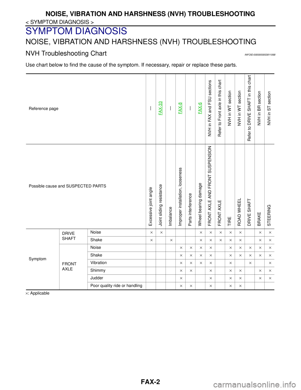
Use chart below to find the cause of the symptom. If necessary, repair or replace these parts.
×: ApplicableReference page
—
FAX-33—
FAX-8—
FAX-6
NVH in FAX and FSU sections
Refer to Front axle in this chart
NVH in WT section
NVH in WT section
Refer to DRIVE SHAFT in this chart
NVH in BR section
NVH in ST section
Possible cause and SUSPECTED PARTS
Excessive joint angle
Joint sliding resistance
Imbalance
Improper installation, looseness
Parts interference
Wheel bearing damage
FRONT AXLE AND FRONT SUSPENSION
FRONT AXLE
TIRE
ROAD WHEEL
DRIVE SHAFT
BRAKE
STEERING
SymptomDRIVE
SHAFTNoise×× ××××× ××
Shake× × ××××× ××
FRONT
AXLENoise×××× ×××××
Shake×××× ×××××
Vibration×××× × × ×
Shimmy×× × ×× ××
Judder× × ×× ××
Poor quality ride or handling×× × ××