Page 2459 of 5121
FRONT DRIVE SHAFT
FAX-31
< ON-VEHICLE REPAIR >
C
E
F
G
H
I
J
K
L
MA
B
FA X
N
O
P
Never reuse dust shield.
3. Install circular clip.
CAUTION:
Never reuse circular clip.
4. Apply balance of the specified amount grease to housing assembly.
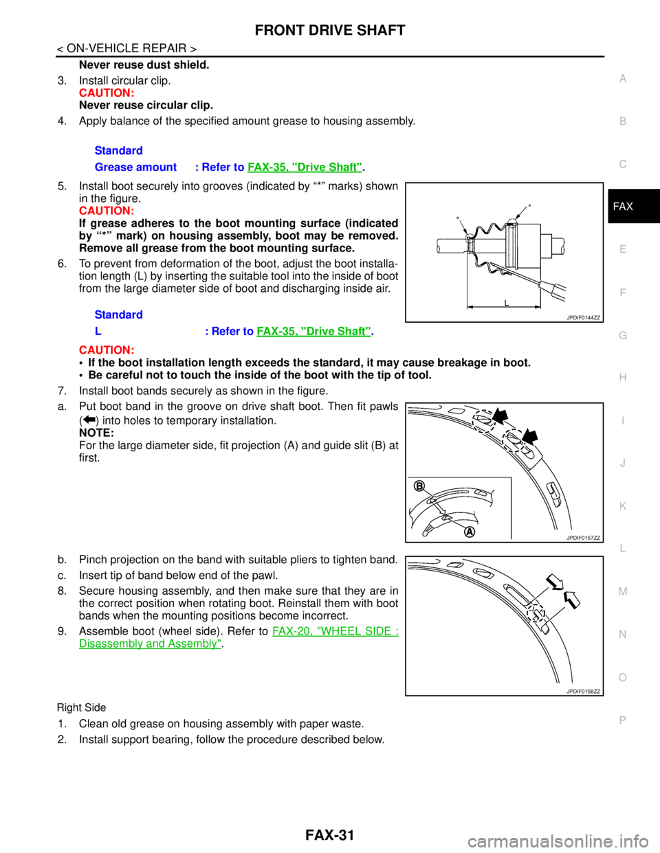
5. Install boot securely into grooves (indicated by “*” marks) shown
in the figure.
CAUTION:
If grease adheres to the boot mounting surface (indicated
by “*” mark) on housing assembly, boot may be removed.
Remove all grease from the boot mounting surface.
6. To prevent from deformation of the boot, adjust the boot installa-
tion length (L) by inserting the suitable tool into the inside of boot
from the large diameter side of boot and discharging inside air.
CAUTION:
If the boot installation length exceeds the standard, it may cause breakage in boot.
Be careful not to touch the inside of the boot with the tip of tool.
7. Install boot bands securely as shown in the figure.
a. Put boot band in the groove on drive shaft boot. Then fit pawls
( ) into holes to temporary installation.
NOTE:
For the large diameter side, fit projection (A) and guide slit (B) at
first.
b. Pinch projection on the band with suitable pliers to tighten band.
c. Insert tip of band below end of the pawl.
8. Secure housing assembly, and then make sure that they are in
the correct position when rotating boot. Reinstall them with boot
bands when the mounting positions become incorrect.
9. Assemble boot (wheel side). Refer to FAX-20, "
WHEEL SIDE :
Disassembly and Assembly".
Right Side
1. Clean old grease on housing assembly with paper waste.
2. Install support bearing, follow the procedure described below. Standard
Grease amount : Refer to FAX-35, "
Drive Shaft".
Standard
L : Refer to FAX-35, "
Drive Shaft".
JPDIF0144ZZ
JPDIF0157ZZ
JPDIF0158ZZ
Page 2460 of 5121
FAX-32
< ON-VEHICLE REPAIR >
FRONT DRIVE SHAFT
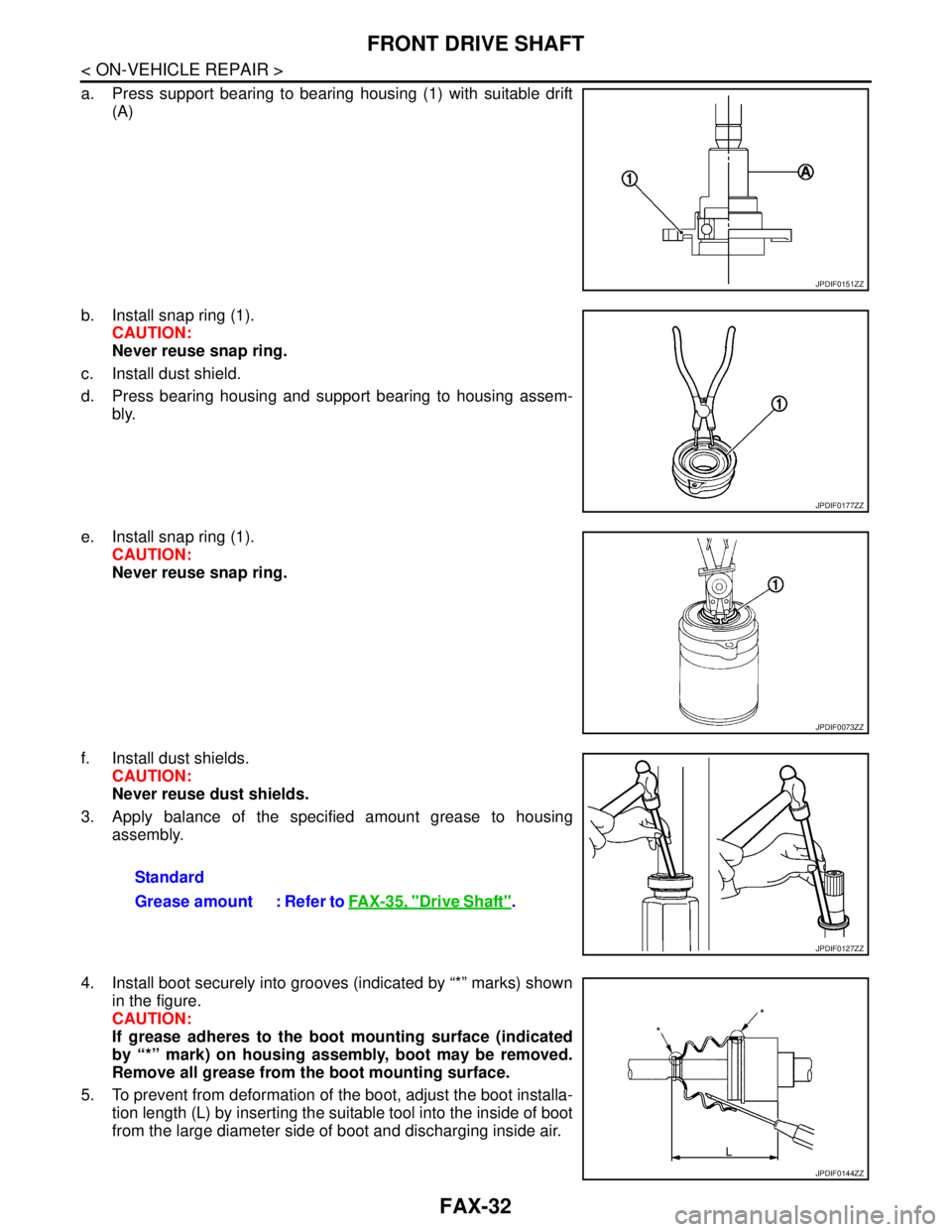
a. Press support bearing to bearing housing (1) with suitable drift
(A)
b. Install snap ring (1).
CAUTION:
Never reuse snap ring.
c. Install dust shield.
d. Press bearing housing and support bearing to housing assem-
bly.
e. Install snap ring (1).
CAUTION:
Never reuse snap ring.
f. Install dust shields.
CAUTION:
Never reuse dust shields.
3. Apply balance of the specified amount grease to housing
assembly.
4. Install boot securely into grooves (indicated by “*” marks) shown
in the figure.
CAUTION:
If grease adheres to the boot mounting surface (indicated
by “*” mark) on housing assembly, boot may be removed.
Remove all grease from the boot mounting surface.
5. To prevent from deformation of the boot, adjust the boot installa-
tion length (L) by inserting the suitable tool into the inside of boot
from the large diameter side of boot and discharging inside air.
JPDIF0151ZZ
JPDIF0177ZZ
JPDIF0073ZZ
Standard
Grease amount : Refer to FAX-35, "
Drive Shaft".
JPDIF0127ZZ
JPDIF0144ZZ
Page 2584 of 5121
PRECAUTIONS
HA-15
< PRECAUTION >
C
D
E
F
G
H
J
K
L
MA
B
HA
N
O
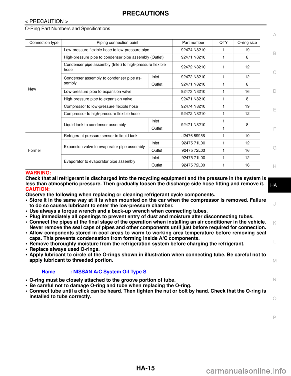
P O-Ring Part Numbers and Specifications
WARNING:
Check that all refrigerant is discharged into the recycling equipment and the pressure in the system is
less than atmospheric pressure. Then gradually loosen the discharge side hose fitting and remove it.
CAUTION:
Observe the following when replacing or cleaning refrigerant cycle components.
Store it in the same way at it is when mounted on the car when the compressor is removed. Failure
to do so causes lubricant to enter the low-pressure chamber.
Use always a torque wrench and a back-up wrench when connecting tubes.
Plug immediately all openings to prevent entry of dust and moisture after disconnecting tubes.
Connect the pipes at the final stage of the operation when installing an air conditioner in the vehicle.
Never remove the seal caps of pipes and other components until just before required for connection.
Allow components stored in cool areas to warm to working area temperature before removing seal
caps. This prevents condensation from forming inside A/C components.
Remove thoroughly moisture from the refrigeration system before charging the refrigerant.
Replace always used O-rings.
Apply lubricant to circle of the O-rings shown in illustration when connecting tube. Be careful not to
apply lubricant to threaded portion.
O-ring must be closely attached to the groove portion of tube.
Be careful not to damage O-ring and tube when replacing the O-ring.
Connect tube until a click can be heard. Then tighten the nut or bolt by hand. Check that the O-ring is
installed to tube correctly.
Connection type Piping connection point Part number QTY O-ring size
NewLow-pressure flexible hose to low-pressure pipe 92474 N8210 1 19
High-pressure pipe to condenser pipe assembly (Outlet) 92471 N8210 1 8
Condenser pipe assembly (Inlet) to high-pressure flexible
hose92472 N8210 1 12
Condenser assembly to condenser pipe as-
semblyInlet 92472 N8210 1 12
Outlet 92471 N8210 1 8
Low-pressure pipe to expansion valve 92473 N8210 1 16
High-pressure pipe to expansion valve 92471 N8210 1 8
Compressor to low-pressure flexible hose 92474 N8210 1 19
Compressor to high-pressure flexible hose 92472 N8210 1 12
Liquid tank to condenser assemblyInlet
92471 N82101
8
Outlet 1
FormerRefrigerant pressure sensor to liquid tank J2476 89956 1 10
Expansion valve to evaporator pipe assemblyInlet 92475 71L00 1 12
Outlet 92475 72L00 1 16
Evaporator to evaporator pipe assemblyInlet 92475 71L00 1 12
Outlet 92475 72L00 1 16
Name : NISSAN A/C System Oil Type S
Page 2586 of 5121
PRECAUTIONS
HA-17
< PRECAUTION >
C
D
E
F
G
H
J
K
L
MA
B
HA
N
O
P
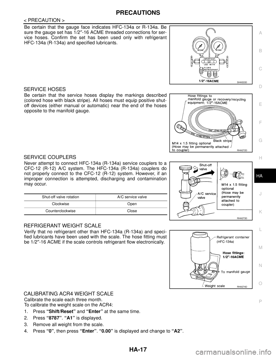
Be certain that the gauge face indicates HFC-134a or R-134a. Be
sure the gauge set has 1/2″-16 ACME threaded connections for ser-
vice hoses. Confirm the set has been used only with refrigerant
HFC-134a (R-134a) and specified lubricants.
SERVICE HOSES
Be certain that the service hoses display the markings described
(colored hose with black stripe). All hoses must equip positive shut-
off devices (either manual or automatic) near the end of the hoses
opposite to the manifold gauge.
SERVICE COUPLERS
Never attempt to connect HFC-134a (R-134a) service couplers to a
CFC-12 (R-12) A/C system. The HFC-134a (R-134a) couplers do
not properly connect to the CFC-12 (R-12) system. However, if an
improper connection is attempted, discharging and contamination
may occur.
REFRIGERANT WEIGHT SCALE
Verify that no refrigerant other than HFC-134a (R-134a) and speci-
fied lubricants have been used with the scale. The hose fitting must
be 1/2″-16 ACME if the scale controls refrigerant flow electronically.
CALIBRATING ACR4 WEIGHT SCALE
Calibrate the scale each three month.
To calibrate the weight scale on the ACR4:
1. Press “Shift/Reset” and “Enter” at the same time.
2. Press “8787”. “A1” is displayed.
3. Remove all weight from the scale.
4. Press “0”, then press “Enter”. “0.00” is displayed and change to “A2”.
SHA533D
RHA272D
Shut-off valve rotation A/C service valve
Clockwise Open
Counterclockwise Close
RHA273D
RHA274D
Page 2587 of 5121
HA-18
< PRECAUTION >
PRECAUTIONS
5. Place a known weight (dumbbell or similar weight), between 4.5 and 8.6 kg (10 and 19 lb.) on the center
of the weight scale.
6. Enter the known weight using four digits. (Example 10 lb. = 10.00, 10.5 lb. = 10.50)
7. Press “Enter”— the display returns to the vacuum mode.
8. Press “Shift/Reset” and “Enter” at the same time.
9. Press “6”— the known weight on the scale is displayed.
10. Remove the known weight from the scale. “0.00” is displayed.
11. Press “Shift/Reset” to return the ACR4 to the program mode.
CHARGING CYLINDER
Using a charging cylinder is not recommended. Refrigerant may be vented into air from cylinder’s top valve
when filling the cylinder with refrigerant. Also, the accuracy of the cylinder is generally less than that of an
electronic scale or of quality recycle/recharge equipment.
Page 2590 of 5121
PREPARATION
HA-21
< PREPARATION >
C
D
E
F
G
H
J
K
L
MA
B
HA
N
O
P
PREPARATION
PREPARATION
Special Service ToolINFOID:0000000003795893
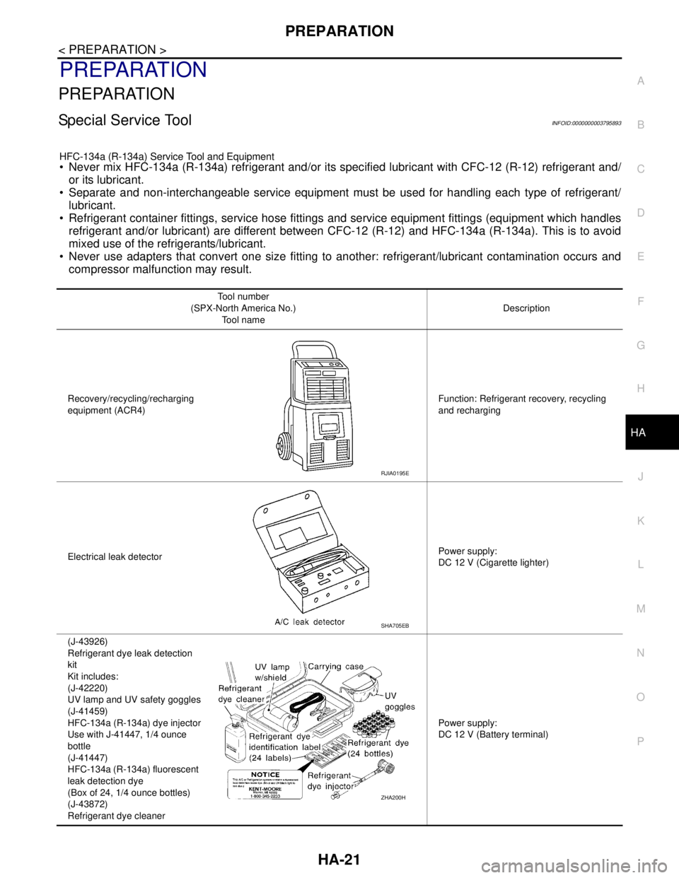
HFC-134a (R-134a) Service Tool and Equipment Never mix HFC-134a (R-134a) refrigerant and/or its specified lubricant with CFC-12 (R-12) refrigerant and/
or its lubricant.
Separate and non-interchangeable service equipment must be used for handling each type of refrigerant/
lubricant.
Refrigerant container fittings, service hose fittings and service equipment fittings (equipment which handles
refrigerant and/or lubricant) are different between CFC-12 (R-12) and HFC-134a (R-134a). This is to avoid
mixed use of the refrigerants/lubricant.
Never use adapters that convert one size fitting to another: refrigerant/lubricant contamination occurs and
compressor malfunction may result.
Tool number
(SPX-North America No.)
Tool nameDescription
Recovery/recycling/recharging
equipment (ACR4)Function: Refrigerant recovery, recycling
and recharging
Electrical leak detectorPower supply:
DC 12 V (Cigarette lighter)
(J-43926)
Refrigerant dye leak detection
kit
Kit includes:
(J-42220)
UV lamp and UV safety goggles
(J-41459)
HFC-134a (R-134a) dye injector
Use with J-41447, 1/4 ounce
bottle
(J-41447)
HFC-134a (R-134a) fluorescent
leak detection dye
(Box of 24, 1/4 ounce bottles)
(J-43872)
Refrigerant dye cleanerPower supply:
DC 12 V (Battery terminal)
RJIA0195E
SHA705EB
ZHA200H
Page 2591 of 5121
HA-22
< PREPARATION >
PREPARATION
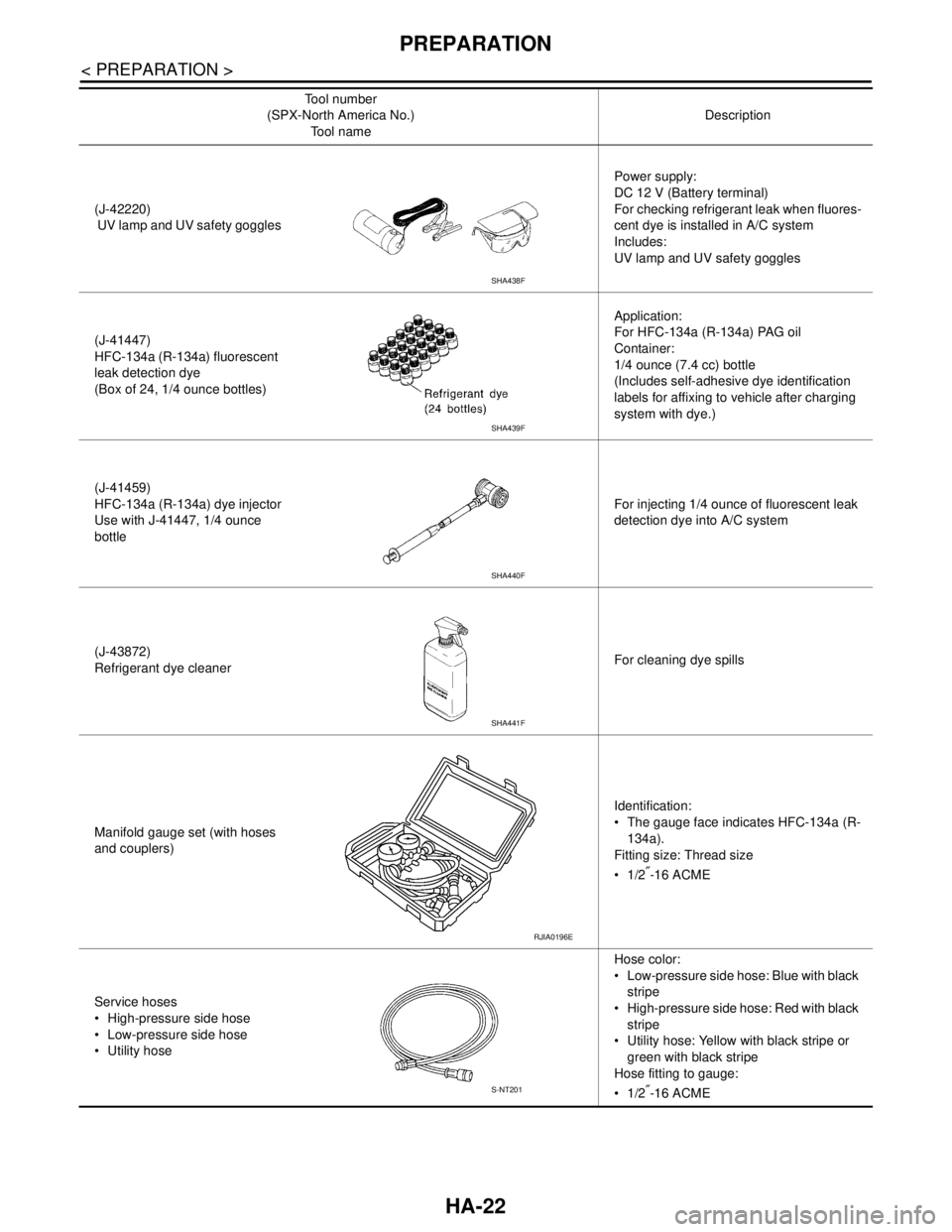
(J-42220)
UV lamp and UV safety gogglesPower supply:
DC 12 V (Battery terminal)
For checking refrigerant leak when fluores-
cent dye is installed in A/C system
Includes:
UV lamp and UV safety goggles
(J-41447)
HFC-134a (R-134a) fluorescent
leak detection dye
(Box of 24, 1/4 ounce bottles)Application:
For HFC-134a (R-134a) PAG oil
Container:
1/4 ounce (7.4 cc) bottle
(Includes self-adhesive dye identification
labels for affixing to vehicle after charging
system with dye.)
(J-41459)
HFC-134a (R-134a) dye injector
Use with J-41447, 1/4 ounce
bottleFor injecting 1/4 ounce of fluorescent leak
detection dye into A/C system
(J-43872)
Refrigerant dye cleanerFor cleaning dye spills
Manifold gauge set (with hoses
and couplers)Identification:
The gauge face indicates HFC-134a (R-
134a).
Fitting size: Thread size
1/2
″-16 ACME
Service hoses
High-pressure side hose
Low-pressure side hose
Utility hoseHose color:
Low-pressure side hose: Blue with black
stripe
High-pressure side hose: Red with black
stripe
Utility hose: Yellow with black stripe or
green with black stripe
Hose fitting to gauge:
1/2
″-16 ACME Tool number
(SPX-North America No.)
Tool nameDescription
SHA438F
SHA439F
SHA440F
SHA441F
RJIA0196E
S-NT201
Page 2593 of 5121
HA-24
< ON-VEHICLE MAINTENANCE >
REFRIGERANT
ON-VEHICLE MAINTENANCE
REFRIGERANT
Collection and ChargeINFOID:0000000003795980
SETTING OF SERVICE TOOLS AND EQUIPMENT
Discharging Refrigerant
Evacuating System and Charging Refrigerant
Procedure
1. Shut-off valve 2. A/C service valve 3. Recovery/recycling recharging
equipment
JSIIA0257ZZ
1. Shut-off valve 2. A/C service valve 3. Recovery/recycling recharging
equipment
4. Vacuum pump 5. Manifold gauge set 6. Refrigerant container (HFC-134a)
7. Weight scale
A. Preferred (best) method B. Alternative method C. For charging
JSIIA0258ZZ