Page 1701 of 5121
![NISSAN TEANA 2008 Service Manual EC-240
< COMPONENT DIAGNOSIS >[VQ25DE, VQ35DE]
P0605 ECM
P0605 ECM
DescriptionINFOID:0000000003856702
The ECM consists of a microcomputer and connectors for signal
input and output and for power suppl NISSAN TEANA 2008 Service Manual EC-240
< COMPONENT DIAGNOSIS >[VQ25DE, VQ35DE]
P0605 ECM
P0605 ECM
DescriptionINFOID:0000000003856702
The ECM consists of a microcomputer and connectors for signal
input and output and for power suppl](/manual-img/5/57391/w960_57391-1700.png)
EC-240
< COMPONENT DIAGNOSIS >[VQ25DE, VQ35DE]
P0605 ECM
P0605 ECM
DescriptionINFOID:0000000003856702
The ECM consists of a microcomputer and connectors for signal
input and output and for power supply. The ECM controls the engine.
DTC LogicINFOID:0000000003856703
DTC DETECTION LOGIC
DTC CONFIRMATION PROCEDURE
1.PRECONDITIONING
If DTC Confirmation Procedure has been previously conducted, always turn ignition switch OFF and wait at
least 10 seconds before conducting the next test.
>> GO TO 2.
2.PERFORM DTC CONFIRMATION PROCEDURE FOR MALFUNCTION A
1. Turn ignition switch ON.
2. Check 1st trip DTC.
Is 1st trip DTC detected?
YES >> Go to EC-241, "Diagnosis Procedure".
NO >> GO TO 3.
3.PERFORM DTC CONFIRMATION PROCEDURE FOR MALFUNCTION B
1. Turn ignition switch ON and wait at least 1 second.
2. Turn ignition switch OFF, wait at least 10 seconds, and then turn it ON.
3. Check 1st trip DTC.
Is 1st trip DTC detected?
YES >> Go to EC-241, "Diagnosis Procedure".
NO >> GO TO 4.
4.PERFORM DTC CONFIRMATION PROCEDURE FOR MALFUNCTION C
1. Turn ignition switch ON and wait at least 1 second.
2. Turn ignition switch OFF, wait at least 10 seconds, and then turn it ON.
3. Repeat step 2 for 32 times.
4. Check 1st trip DTC.
Is 1st trip DTC detected?
YES >> Go to EC-241, "Diagnosis Procedure".
NO >> INSPECTION END
PBIA9222J
DTC No. Trouble diagnosis name DTC detecting condition Possible cause
P0605 Engine control moduleA) ECM calculation function is a malfunctioning.
ECM B) ECM EEP-ROM system is a malfunctioning.
C) ECM self shut-off function is a malfunctioning.
Page 3260 of 5121

MWI-6
< FUNCTION DIAGNOSIS >
METER SYSTEM
FUNCTION DIAGNOSIS
METER SYSTEM
METER SYSTEM
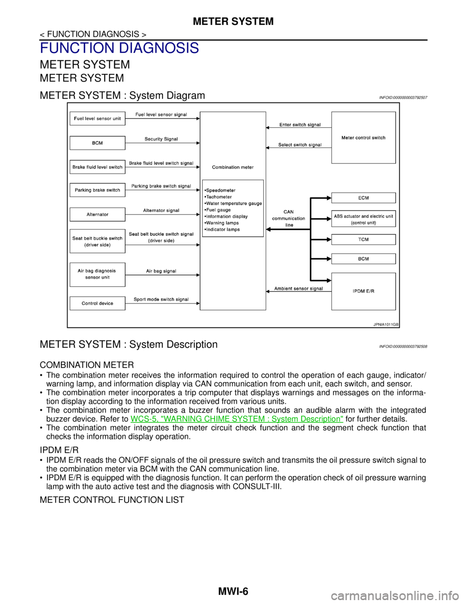
METER SYSTEM : System DiagramINFOID:0000000003792507
METER SYSTEM : System DescriptionINFOID:0000000003792508
COMBINATION METER
The combination meter receives the information required to control the operation of each gauge, indicator/
warning lamp, and information display via CAN communication from each unit, each switch, and sensor.
The combination meter incorporates a trip computer that displays warnings and messages on the informa-
tion display according to the information received from various units.
The combination meter incorporates a buzzer function that sounds an audible alarm with the integrated
buzzer device. Refer to WCS-5, "
WARNING CHIME SYSTEM : System Description" for further details.
The combination meter integrates the meter circuit check function and the segment check function that
checks the information display operation.
IPDM E/R
IPDM E/R reads the ON/OFF signals of the oil pressure switch and transmits the oil pressure switch signal to
the combination meter via BCM with the CAN communication line.
IPDM E/R is equipped with the diagnosis function. It can perform the operation check of oil pressure warning
lamp with the auto active test and the diagnosis with CONSULT-III.
METER CONTROL FUNCTION LIST
JPNIA1011GB
Page 3281 of 5121

MWI
METER SYSTEM
MWI-27
< FUNCTION DIAGNOSIS >
C
D
E
F
G
H
I
J
K
L
MB A
O
P
METER ILLUMINATION CONTROL : Component DescriptionINFOID:0000000003796391
INFORMATION DISPLAY
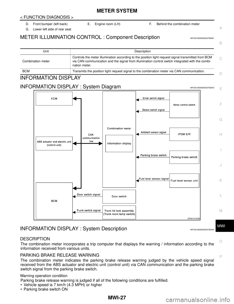
INFORMATION DISPLAY : System DiagramINFOID:0000000003792543
INFORMATION DISPLAY : System DescriptionINFOID:0000000003792544
DESCRIPTION
The combination meter incorporates a trip computer that displays the warning / information according to the
information received from various units.
PARKING BRAKE RELEASE WARNING
The combination meter indicates the parking brake release warning judged by the vehicle speed signal
received from the ABS actuator and electric unit (control unit) via CAN communication and the parking brake
switch signal from the parking brake switch.
Warning operation condition
Parking brake release warning is judged if all of the following conditions are fulfilled.
Vehicle speed is 7 km/h (4.3 MPH) or higher
Parking brake switch ON
D. Front bumper (left back) E. Engine room (LH) F. Behind the combination meter
G. Lower left side of rear seat
Unit Description
Combination meterControls the meter illumination according to the position light request signal transmitted from BCM
via CAN communication and the signal from illumination control switch integrated with the combi-
nation meter.
BCM Transmits the position light request signal to the combination meter via CAN communication.
JPNIA1016GB