2008 NISSAN TEANA trunk release
[x] Cancel search: trunk releasePage 1286 of 5121
![NISSAN TEANA 2008 Service Manual DLK-70
< COMPONENT DIAGNOSIS >[WITH INTELLIGENT KEY SYSTEM]
TRUNK LID OPENER SWITCH
TRUNK LID OPENER SWITCH
DescriptionINFOID:0000000003794870
Output trunk lid open signal to BCM.
Component Function C NISSAN TEANA 2008 Service Manual DLK-70
< COMPONENT DIAGNOSIS >[WITH INTELLIGENT KEY SYSTEM]
TRUNK LID OPENER SWITCH
TRUNK LID OPENER SWITCH
DescriptionINFOID:0000000003794870
Output trunk lid open signal to BCM.
Component Function C](/manual-img/5/57391/w960_57391-1285.png)
DLK-70
< COMPONENT DIAGNOSIS >[WITH INTELLIGENT KEY SYSTEM]
TRUNK LID OPENER SWITCH
TRUNK LID OPENER SWITCH
DescriptionINFOID:0000000003794870
Output trunk lid open signal to BCM.
Component Function CheckINFOID:0000000003794871
1.CHECK FUNCTION
Check trunk lid opener switch (“TR/BD OPEN SW”) in “Data Monitor mode with CONSULT-III.
Is the inspection result normal?
YES >> Trunk lid opener switch is OK.
NO >> Refer to DLK-70, "
Diagnosis Procedure".
Diagnosis ProcedureINFOID:0000000003794872
1.CHECK TRUNK LID OPENER INPUT SIGNAL
1. Turn ignition switch OFF.
2. Disconnect trunk lid opener switch connector.
3. Check signal between trunk lid opener switch harness connector and ground with oscilloscope.
Is the inspection result normal?
YES >> GO TO 3.
NO >> GO TO 2.
2.CHECK TRUNK LID OPENER SWITCH CIRCUIT
1. Disconnect BCM connector.
2. Check continuity between BCM harness connector and trunk lid opener switch harness connector.
3. Check continuity between BCM harness connector and ground.
Is the inspection result normal?
YES >> Replace BCM. Refer to BCS-78, "Removal and Installation".
Monitor item Condition
TR/BD OPEN SWTrunk lid opener switch is pressed: ON
Trunk lid opener switch is released: OFF
(+)
(–)Signal
(Reference value) Trunk lid opener switch
Connector Terminal
M25 1 Ground
JPMIA0011GB
BCM Trunk lid opener switch
Continuity
Connector Terminal Connector Terminal
M121 67 M25 1 Existed
BCM
GroundContinuity
Connector Terminal
M121 67 Not existed
Page 1287 of 5121
![NISSAN TEANA 2008 Service Manual TRUNK LID OPENER SWITCH
DLK-71
< COMPONENT DIAGNOSIS >[WITH INTELLIGENT KEY SYSTEM]
C
D
E
F
G
H
I
J
L
MA
B
DLK
N
O
P
NO >> Repair or replace harness.
3.CHECK TRUNK LID OPENER SWITCH GROUND CIRCUIT
Che NISSAN TEANA 2008 Service Manual TRUNK LID OPENER SWITCH
DLK-71
< COMPONENT DIAGNOSIS >[WITH INTELLIGENT KEY SYSTEM]
C
D
E
F
G
H
I
J
L
MA
B
DLK
N
O
P
NO >> Repair or replace harness.
3.CHECK TRUNK LID OPENER SWITCH GROUND CIRCUIT
Che](/manual-img/5/57391/w960_57391-1286.png)
TRUNK LID OPENER SWITCH
DLK-71
< COMPONENT DIAGNOSIS >[WITH INTELLIGENT KEY SYSTEM]
C
D
E
F
G
H
I
J
L
MA
B
DLK
N
O
P
NO >> Repair or replace harness.
3.CHECK TRUNK LID OPENER SWITCH GROUND CIRCUIT
Check continuity between trunk lid opener switch harness connector and ground.
Is the inspection result normal?
YES >> GO TO 4.
NO >> Repair or replace harness.
4.CHECK TRUNK LID OPENER SWITCH
Refer to DLK-71, "
Component Inspection".
Is the inspection result normal?
YES >> GO TO 5.
NO >> Replace trunk lid opener switch. Refer to DLK-243, "
Removal and Installation".
5.CHECK INTERMITTENT INCIDENT
Refer to GI-35, "
Intermittent Incident".
>> INSPECTION END
Component InspectionINFOID:0000000003794873
1.CHECK TRUNK LID OPENER SWITCH
1. Turn ignition switch OFF.
2. Disconnect trunk lid opener switch connector.
3. Check continuity between trunk lid opener switch terminal.
Is the inspection result normal?
YES >> INSPECTION END
NO >> Replace trunk lid opener switch. Refer to DLK-243, "
Removal and Installation".
Trunk lid opener switch
GroundContinuity
Connector Terminal
M25 2 Existed
Trunk lid opener switch
Condition Continuity
Te r m i n a l
12ON (press and hold) Existed
OFF (release) Not existed
Page 1290 of 5121
![NISSAN TEANA 2008 Service Manual DLK-74
< COMPONENT DIAGNOSIS >[WITH INTELLIGENT KEY SYSTEM]
TRUNK LID OPENER REQUEST SWITCH
TRUNK LID OPENER REQUEST SWITCH
DescriptionINFOID:0000000003794878
Performs trunk lid open request when it i NISSAN TEANA 2008 Service Manual DLK-74
< COMPONENT DIAGNOSIS >[WITH INTELLIGENT KEY SYSTEM]
TRUNK LID OPENER REQUEST SWITCH
TRUNK LID OPENER REQUEST SWITCH
DescriptionINFOID:0000000003794878
Performs trunk lid open request when it i](/manual-img/5/57391/w960_57391-1289.png)
DLK-74
< COMPONENT DIAGNOSIS >[WITH INTELLIGENT KEY SYSTEM]
TRUNK LID OPENER REQUEST SWITCH
TRUNK LID OPENER REQUEST SWITCH
DescriptionINFOID:0000000003794878
Performs trunk lid open request when it is pressed.
Component Function CheckINFOID:0000000003794879
1.CHECK FUNCTION
Check trunk lid opener request switch (“REQ SW -BD/TR ”) in Data Monitor mode.
Is the inspection result normal?
YES >> Trunk lid opener request switch is OK.
NO >> Refer to DLK-74, "
Diagnosis Procedure".
Diagnosis ProcedureINFOID:0000000003794880
1.CHECK TRUNK LID OPENER SWITCH OUTPUT SIGNAL
1. Turn ignition switch OFF.
2. Disconnect trunk lid opener request switch connector.
3. Check signal between trunk lid opener request switch harness connector and ground with oscilloscope.
Is the inspection result normal?
YES >> GO TO 3.
NO >> GO TO 2.
2.CHECK TRUNK LID OPENER REQUEST SWITCH CIRCUIT
1. Disconnect BCM connector.
2. Check continuity between BCM harness connector and trunk lid opener request switch harness connec-
tor.
3. Check continuity between BCM harness connector and ground.
Is the inspection result normal?
Monitor item Condition
REQ SW -BD/TR Trunk lid opener request switch is pressed: ON
Trunk lid opener request switch is released: OFF
(+)
(–)Signal
(Reference value) Trunk lid opener request switch
Connector Terminal
T6 1 Ground
JPMIA0016GB
BCM Trunk lid opener request switch
Continuity
Connector Terminal Connector Terminal
M121 61 T6 1 Existed
BCM
GroundContinuity
Connector Terminal
M121 61 Not existed
Page 1291 of 5121
![NISSAN TEANA 2008 Service Manual TRUNK LID OPENER REQUEST SWITCH
DLK-75
< COMPONENT DIAGNOSIS >[WITH INTELLIGENT KEY SYSTEM]
C
D
E
F
G
H
I
J
L
MA
B
DLK
N
O
P
YES >> Replace BCM. Refer to BCS-78, "Removal and Installation".
NO >> Repa NISSAN TEANA 2008 Service Manual TRUNK LID OPENER REQUEST SWITCH
DLK-75
< COMPONENT DIAGNOSIS >[WITH INTELLIGENT KEY SYSTEM]
C
D
E
F
G
H
I
J
L
MA
B
DLK
N
O
P
YES >> Replace BCM. Refer to BCS-78, "Removal and Installation".
NO >> Repa](/manual-img/5/57391/w960_57391-1290.png)
TRUNK LID OPENER REQUEST SWITCH
DLK-75
< COMPONENT DIAGNOSIS >[WITH INTELLIGENT KEY SYSTEM]
C
D
E
F
G
H
I
J
L
MA
B
DLK
N
O
P
YES >> Replace BCM. Refer to BCS-78, "Removal and Installation".
NO >> Repair or replace harness.
3.CHECK TRUNK LID OPENER REQUEST SWITCH GROUND CIRCUIT
Check continuity between trunk lid opener request switch harness connector and ground.
Is the inspection result normal?
YES >> GO TO 4.
NO >> Repair or replace harness.
4.CHECK TRUNK LID OPENER REQUEST SWITCH
Refer to DLK-75, "
Component Inspection".
Is the inspection result normal?
YES >> GO TO 5.
NO >> Replace trunk lid opener request switch. Refer to DLK-242, "
Removal and Installation".
5.CHECK INTERMITTENT INCIDENT
Refer to GI-35, "
Intermittent Incident".
>> INSPECTION END
Component InspectionINFOID:0000000003794881
1.CHECK TRUNK LID OPENER REQUEST SWITCH
1. Turn ignition switch OFF.
2. Disconnect trunk lid opener request switch connector.
3. Check trunk lid opener request switch.
Is the inspection result normal?
YES >> INSPECTION END
NO >> Replace trunk lid opener request switch. Refer to DLK-242, "
Removal and Installation".
Trunk lid opener request switch
GroundContinuity
Connector Terminal
T6 2 Existed
Trunk lid opener request switch
Condition Continuity
Te r m i n a l
12Trunk lid opener request
switchPressed Existed
Released Not existed
Page 1300 of 5121
![NISSAN TEANA 2008 Service Manual DLK-84
< COMPONENT DIAGNOSIS >[WITH INTELLIGENT KEY SYSTEM]
INTELLIGENT KEY
INTELLIGENT KEY
DescriptionINFOID:0000000003794893
The following functions are available when having and carrying electronic NISSAN TEANA 2008 Service Manual DLK-84
< COMPONENT DIAGNOSIS >[WITH INTELLIGENT KEY SYSTEM]
INTELLIGENT KEY
INTELLIGENT KEY
DescriptionINFOID:0000000003794893
The following functions are available when having and carrying electronic](/manual-img/5/57391/w960_57391-1299.png)
DLK-84
< COMPONENT DIAGNOSIS >[WITH INTELLIGENT KEY SYSTEM]
INTELLIGENT KEY
INTELLIGENT KEY
DescriptionINFOID:0000000003794893
The following functions are available when having and carrying electronic ID.
Door lock/unlock
Trunk lid open
Engine start
Remote control entry function and panic alarm function have specific buttons.
Component Function CheckINFOID:0000000003794894
1.CHECK FUNCTION
Check remote keyless entry receiver (“RKE OPE COUN1”) in Data Monitor mode with CONSULT-III.
Is the inspection result normal?
YES >> Intelligent Key is OK.
NO >> Refer to DLK-84, "
Diagnosis Procedure".
Diagnosis ProcedureINFOID:0000000003794895
1.CHECK INTELLIGENT KEY BATTERY
Check by connecting a resistance (approximately 300 Ω) so that the
current value becomes about 10 mA.
Is the measurement value within the specification?
YES >> Replace Intelligent Key.
NO >> Replace Intelligent Key battery. Refer to DLK-84, "
Com-
ponent Inspection".
Component InspectionINFOID:0000000003794896
1. REPLACE INTELLIGENT KEY BATTERY
1. Release the lock knob at the back of the Intelligent Key and remove the mechanical key.
2. Insert a flat-bladed screwdriver (A) wrapped with a cloth into the
slit of the corner and twist it to separate the upper part from the
lower part.
CAUTION:
Never touch the circuit board or battery terminal.
The key fob is water-resistant. However, if it does get wet,
immediately wipe it dry.
3. Replace the battery with new one.
Monitor item Condition
RKE OPE COUN1 Check that the numerical value is changing while operating on the Intelligent Key.
Standard : Approx. 2.5 - 3.0 V
OCC0607D
PIIB6221E
Page 2505 of 5121

GI-12
< HOW TO USE THIS MANUAL >
HOW TO READ WIRING DIAGRAMS
ignition switch is “OFF”,
doors, hood and trunk lid/back door are closed,
pedals are not depressed, and
parking brake is released.
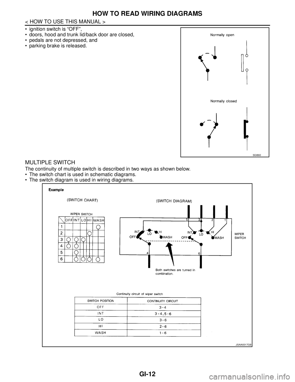
MULTIPLE SWITCH
The continuity of multiple switch is described in two ways as shown below.
The switch chart is used in schematic diagrams.
The switch diagram is used in wiring diagrams.
SGI860
JSAIA0017GB
Page 3230 of 5121

MA-42
< ON-VEHICLE MAINTENANCE >
BODY MAINTENANCE
BODY MAINTENANCE
LOCKS, HINGES AND HOOD LATCH
LOCKS, HINGES AND HOOD LATCH : LubricatingINFOID:0000000003858318
For hood and hood lock illustration.
Hood: Refer to DLK-191, "
HOOD ASSEMBLY : Exploded View".
Hood lock control: Refer to DLK-220, "
Exploded View".
For door and door lock illustration.
Front door: Refer to DLK-201, "
DOOR ASSEMBLY : Exploded View".
Front door lock: Refer to DLK-222, "
DOOR LOCK : Exploded View".
Rear door: Refer to DLK-207, "
DOOR ASSEMBLY : Exploded View".
Rear door lock: Refer to DLK-227, "
DOOR LOCK : Exploded View".
For trunk lid and trunk lid lock illustration.
Trunk lid: Refer to DLK-213, "
TRUNK LID ASSEMBLY : Exploded View".
Trunk lid lock: Refer to DLK-231, "
Exploded View".
SEAT BELT, BUCKLES, RETRACTORS, ANCHORS AND ADJUSTERS
SEAT BELT, BUCKLES, RETRACTORS, ANCHORS AND ADJUSTERS : Inspection
INFOID:0000000003858319
For front seat belt illustration. Refer to SB-5, "SEAT BELT RETRACTOR : Exploded View".
For rear seat belt illustration. Refer to SB-10, "
SEAT BELT RETRACTOR : Exploded View".
CAUTION:
After any collision, inspect all seat belt assemblies, including retractors and other attached hard-
wares (I.e. anchor bolt, guide rail set). Nissan recommends to replace all seat belt assemblies in use
during a collision, unless not damaged and properly operating after minor collision.
Also inspect seat belt assemblies not in use during a collision, and replace if damaged or improperly
operating.
Seat belt pre-tensioner should be replaced even if the seat belts are not in use during a frontal colli-
sion where the driver and passenger air bags are deployed.
If any component of seat belt assembly is questionable, do not repair.
Replace as seat belt assembly.
If webbing is cut, frayed, or damaged, replace belt assembly.
Never oil tongue and buckle.
Use a genuine NISSAN seat belt assembly.
For details, refer to SB-3, "
SEAT BELT RETRACTOR : Inspection" , SB-8, "SEAT BELT RETRACTOR :
Inspection" in SB section.
Check anchors for loose mounting
Check belts for damage
Check retractor for smooth operation
Check function of buckles and tongues when buckled and released
BODY CORROSION
BODY CORROSION : Checking Body CorrosionINFOID:0000000003858320
Visually check body panels for collision damage (scratches, chipping, rubbing, etc.) or damage to the anti-cor-
rosion materials. In particular, check the following locations.
HEMMED PANELS
Hood front end, door lower end, trunk lid rear end, etc.
PA N E L J O I N T
Side sill of rear fender and center pillar, rear wheel housing of rear fender, around strut tower in engine com-
partment, etc.
PA N E L E D G E
Trunk lid opening, sunroof opening, fender wheel-arch flange, fuel filler lid flange, around holes in panel, etc.
PARTS CONTACT
Waist moulding, windshield moulding, bumper, etc.
Page 3321 of 5121

MWI
COMBINATION METER
MWI-67
< ECU DIAGNOSIS >
C
D
E
F
G
H
I
J
K
L
MB A
O
P
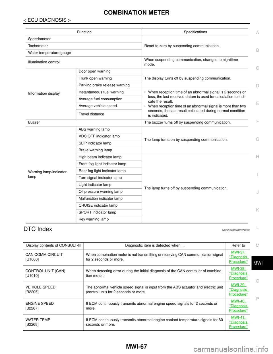
DTC IndexINFOID:0000000003792591
Function Specifications
Speedometer
Reset to zero by suspending communication. Tachometer
Water temperature gauge
Illumination controlWhen suspending communication, changes to nighttime
mode.
Information displayDoor open warning
The display turns off by suspending communication. Trunk open warning
Parking brake release warning
Instantaneous fuel warning When reception time of an abnormal signal is 2 seconds or
less, the last received datum is used for calculation to indi-
cate the result.
When reception time of an abnormal signal is more than two
seconds, the last result calculated during normal condition
is indicated. Average fuel consumption
Average vehicle speed
Travel distance
Buzzer The buzzer turns off by suspending communication.
Warning lamp/indicator
lampABS warning lamp
The lamp turns on by suspending communication. VDC OFF indicator lamp
SLIP indicator lamp
Brake warning lamp
High beam indicator lamp
The lamp turns off by suspending communication. Front fog light indicator lamp
Rear fog light indicator lamp
Turn signal indicator lamp
Light indicator lamp
Oil pressure warning lamp
Malfunction indicator lamp
CRUISE indicator lamp
SPORT indicator lamp
Key warning lamp
Display contents of CONSULT-III Diagnostic item is detected when ... Refer to
CAN COMM CIRCUIT
[U1000]When combination meter is not transmitting or receiving CAN communication signal
for 2 seconds or more.MWI-37,
"Diagnosis
Procedure"
CONTROL UNIT (CAN)
[U1010]When detecting error during the initial diagnosis of the CAN controller of combina-
tion meter.MWI-38, "Diagnosis
Procedure"
VEHICLE SPEED
[B2205]The abnormal vehicle speed signal is input from the ABS actuator and electric unit
(control unit) for 2 seconds or more.MWI-39, "Diagnosis
Procedure"
ENGINE SPEED
[B2267]If ECM continuously transmits abnormal engine speed signals for 2 seconds or
more.MWI-40, "Diagnosis
Procedure"
WATER TEMP
[B2268]If ECM continuously transmits abnormal engine coolant temperature signals for 60
seconds or more.MWI-41, "Diagnosis
Procedure"