2008 NISSAN TEANA seats
[x] Cancel search: seatsPage 212 of 5121
![NISSAN TEANA 2008 Service Manual AV-68
< FUNCTION DIAGNOSIS >[BASE AUDIO AND DISPLAY SYSTEM]
DIAGNOSIS SYSTEM (AV CONTROL UNIT)
Displays the communication status between AV control unit (mas-
ter unit) and each unit.
The error co NISSAN TEANA 2008 Service Manual AV-68
< FUNCTION DIAGNOSIS >[BASE AUDIO AND DISPLAY SYSTEM]
DIAGNOSIS SYSTEM (AV CONTROL UNIT)
Displays the communication status between AV control unit (mas-
ter unit) and each unit.
The error co](/manual-img/5/57391/w960_57391-211.png)
AV-68
< FUNCTION DIAGNOSIS >[BASE AUDIO AND DISPLAY SYSTEM]
DIAGNOSIS SYSTEM (AV CONTROL UNIT)
Displays the communication status between AV control unit (mas-
ter unit) and each unit.
The error counter displays “OK” if any malfunction was not
detected in the past and displays “0” if a malfunction is detected. It
increases by 1 if the condition is normal at the next ignition switch
ON cycle. The upper limit of the counter is 39.
If it resets, the error counter is erased.
Delete Unit Connection Log
Deletes any unit connection records and error records from the AV
control unit memory. (Clear the records of the unit that has been
removed)
CONSULT-III Function (MULTI AV)INFOID:0000000003882712
CONSULT-III FUNCTIONS
CONSULT-III performs the following functions via the communication with the AV control unit.
AV COMMUNICATION
When “AV communication” of “CAN Diag Support Monitor” is selected, the following function will be performed.
SELF-DIAGNOSIS RESULTS
In CONSULT-III self-diagnosis, self-diagnosis results and error history are displayed collectively.
The timing is displayed as “0” if any of the error codes [U1000], [U1010], [U1300] and [U1310] is detected.
The counter increases by 1 if the condition is normal at the next ignition switch ON cycle.
Self-diagnosis Results Display Item
ItemsStatus
(Current)Counter
(Past)
C Tx(ITM–SW) OK / UNKWN OK / 0 – 39
C Rx(PrimarySW–ITM) OK / UNKWN OK / 0 – 39
C Rx(RrSeatSW–ITM) OK / UNKWN OK / 0 – 39
C Rx(RearCamera–ITM) OK / UNKWN OK / 0 – 39
JSNIA1439GB
JSNIA0154GB
Diagnosis mode Description
Ecu Identification The part number of AV control unit can be checked.
Self Diagnostic ResultPerforms a diagnosis on the AV control unit and a connection diagnosis for the communication
circuit of the Multi AV system, and displays the current and past malfunctions collectively.
Data Monitor The diagnosis of vehicle signal that is input to the AV control unit can be performed.
AV communicationAV&NAVI C/UDisplays the communication status from AV control unit to each unit as well as the error
counter.
AUDIO Displays the AV control unit communication status and the error counter.
Error item Detection logic Possible malfunction factor/Action to take
CAN COMM CIRCUIT [U1000]CAN communication malfunction is detect-
ed.Refer to AV- 7 2 , "
DiagnosisProcedure".
Page 355 of 5121
![NISSAN TEANA 2008 Service Manual AV
DIAGNOSIS SYSTEM (AV CONTROL UNIT)
AV-211
< FUNCTION DIAGNOSIS >[BOSE AUDIO WITHOUT NAVIGATION]
C
D
E
F
G
H
I
J
K
L
MB A
O
P Delete Unit Connection Log
Deletes any unit connection records and error NISSAN TEANA 2008 Service Manual AV
DIAGNOSIS SYSTEM (AV CONTROL UNIT)
AV-211
< FUNCTION DIAGNOSIS >[BOSE AUDIO WITHOUT NAVIGATION]
C
D
E
F
G
H
I
J
K
L
MB A
O
P Delete Unit Connection Log
Deletes any unit connection records and error](/manual-img/5/57391/w960_57391-354.png)
AV
DIAGNOSIS SYSTEM (AV CONTROL UNIT)
AV-211
< FUNCTION DIAGNOSIS >[BOSE AUDIO WITHOUT NAVIGATION]
C
D
E
F
G
H
I
J
K
L
MB A
O
P Delete Unit Connection Log
Deletes any unit connection records and error records from the AV
control unit memory. (Clear the records of the unit that has been
removed)
CONSULT-III Function (MULTI AV)INFOID:0000000003765658
CONSULT-III FUNCTIONS
CONSULT-III performs the following functions via the communication with the AV control unit.
AV COMMUNICATION
When “AV communication” of “CAN Diag Support Monitor” is selected, the following function will be performed.
SELF-DIAGNOSIS RESULTS
In CONSULT-III self-diagnosis, self-diagnosis results and error history are displayed collectively.
The timing is displayed as “0” if any of the error codes [U1000], [U1010], [U1300] and [U1310] is detected.
The counter increases by 1 if the condition is normal at the next ignition switch ON cycle.
Self-diagnosis Results Display Item
C Rx(RrSeatSW–ITM) OK / UNKWN OK / 0 – 39
C Rx(Amp–ITM) OK / UNKWN OK / 0 – 39
C Rx(RearCamera–ITM) OK / UNKWN OK / 0 – 39
C Rx(DVD–ITM) OK / UNKWN OK / 0 – 39
C Rx(AmpAudio–ITM) OK / UNKWN OK / 0 – 39
C Rx(DVDAudio–ITM) OK / UNKWN OK / 0 – 39ItemsStatu s
(Current)Counter
(Past)
JSNIA0154GB
Diagnosis mode Description
Ecu Identification The part number of AV control unit can be checked.
Self Diagnostic ResultPerforms a diagnosis on the AV control unit and a connection diagnosis for the communication
circuit of the Multi AV system, and displays the current and past malfunctions collectively.
Data Monitor The diagnosis of vehicle signal that is input to the AV control unit can be performed.
AV communicationAV&NAVI C/UDisplays the communication status from AV control unit to each unit as well as the error
counter.
AUDIO Displays the AV control unit communication status and the error counter.
Error item Detection logic Possible malfunction factor/Action to take
CAN COMM CIRCUIT [U1000]CAN communication malfunction is detect-
ed.Refer to AV- 2 1 6 , "
DiagnosisProcedure".
CONTROL UNIT (CAN) [U1010]CAN initial diagnosis malfunction is detect-
ed.
Replace the AV control unit.
Refer toAV- 3 7 8 , "
Removal and Installation"
AV- 3 7 8 , "
Removal and Installation". CONTROL UNIT (AV) [U1310]AV communication circuit initial diagnosis
malfunction is detected.
Control Unit FLASH-ROM [U1200]
AV control unit malfunction is detected.
CAN CONT [U1216]
Page 577 of 5121
![NISSAN TEANA 2008 Service Manual AV
DIAGNOSIS SYSTEM (AV CONTROL UNIT)
AV-433
< FUNCTION DIAGNOSIS >[BOSE AUDIO WITH NAVIGATION]
C
D
E
F
G
H
I
J
K
L
MB A
O
P Vehicle CAN Diagnosis
CAN communication status and error counter is displ NISSAN TEANA 2008 Service Manual AV
DIAGNOSIS SYSTEM (AV CONTROL UNIT)
AV-433
< FUNCTION DIAGNOSIS >[BOSE AUDIO WITH NAVIGATION]
C
D
E
F
G
H
I
J
K
L
MB A
O
P Vehicle CAN Diagnosis
CAN communication status and error counter is displ](/manual-img/5/57391/w960_57391-576.png)
AV
DIAGNOSIS SYSTEM (AV CONTROL UNIT)
AV-433
< FUNCTION DIAGNOSIS >[BOSE AUDIO WITH NAVIGATION]
C
D
E
F
G
H
I
J
K
L
MB A
O
P Vehicle CAN Diagnosis
CAN communication status and error counter is displayed.
The error counter displays “OK” if any malfunction was not
detected in the past and displays “0” if a malfunction is detected. It
increases by 1 if the condition is normal at the next ignition switch
ON cycle. The upper limit of the counter is 39.
The error counter is erased if reset.
AV COMM Diagnosis
Displays the communication status between AV control unit (mas-
ter unit) and each unit.
The error counter displays “OK” if any malfunction was not
detected in the past and displays “0” if a malfunction is detected. It
increases by 1 if the condition is normal at the next ignition switch
ON cycle. The upper limit of the counter is 39.
If it resets, the error counter is erased.
Delete Unit Connection Log
Deletes any unit connection records and error records from the AV
control unit memory. (Clear the records of the unit that has been
removed)
Initialize Settings
Items Display (Current)Malfunction counter
(Past)
Tx (HVAC) OK / UNKWN OK / 0 – 39
Rx (ECM) OK / UNKWN OK / 0 – 39
Rx (Cluster) OK / UNKWN OK / 0 – 39
Rx (BCM) OK / UNKWN OK / 0 – 39
Rx (HVAC) OK / UNKWN OK / 0 – 39
Rx (USM) OK / UNKWN OK / 0 – 39
JSNIA1287GB
ItemsStatu s
(Current)Counter
(Past)
C Tx(ITM–SW) OK / UNKWN OK / 0 – 39
C Rx(PrimarySW–ITM) OK / UNKWN OK / 0 – 39
C Rx(RrSeatSW–ITM) OK / UNKWN OK / 0 – 39
C Rx(Amp–ITM) OK / UNKWN OK / 0 – 39
C Rx(RearCamera–ITM) OK / UNKWN OK / 0 – 39
C Rx(DVD–ITM) OK / UNKWN OK / 0 – 39
C Rx(DVDNavi–ITM) OK / UNKWN OK / 0 – 39
C Rx(AmpAudio–ITM) OK / UNKWN OK / 0 – 39
C Rx(DVDAudio–ITM) OK / UNKWN OK / 0 – 39
JSNIA1292GB
JSNIA0522GB
Page 1401 of 5121
![NISSAN TEANA 2008 Service Manual SQUEAK AND RATTLE TROUBLE DIAGNOSES
DLK-185
< SYMPTOM DIAGNOSIS >[WITH INTELLIGENT KEY SYSTEM]
C
D
E
F
G
H
I
J
L
MA
B
DLK
N
O
P
SEATS
When isolating seat noise it is important to note the position the NISSAN TEANA 2008 Service Manual SQUEAK AND RATTLE TROUBLE DIAGNOSES
DLK-185
< SYMPTOM DIAGNOSIS >[WITH INTELLIGENT KEY SYSTEM]
C
D
E
F
G
H
I
J
L
MA
B
DLK
N
O
P
SEATS
When isolating seat noise it is important to note the position the](/manual-img/5/57391/w960_57391-1400.png)
SQUEAK AND RATTLE TROUBLE DIAGNOSES
DLK-185
< SYMPTOM DIAGNOSIS >[WITH INTELLIGENT KEY SYSTEM]
C
D
E
F
G
H
I
J
L
MA
B
DLK
N
O
P
SEATS
When isolating seat noise it is important to note the position the seat is in and the load placed on the seat
when the noise occurs. These conditions should be duplicated when verifying and isolating the cause of the
noise.
Cause of seat noise include:
1. Headrest rods and holder
2. A squeak between the seat pad cushion and frame
3. Rear seatback lock and bracket
These noises can be isolated by moving or pressing on the suspected components while duplicating the con-
ditions under which the noise occurs. Most of these incidents can be repaired by repositioning the component
or applying urethane tape to the contact area.
UNDERHOOD
Some interior noise may be caused by components under the hood or on the engine wall. The noise is then
transmitted into the passenger compartment.
Causes of transmitted underhood noise include:
1. Any component mounted to the engine wall
2. Components that pass through the engine wall
3. Engine wall mounts and connectors
4. Loose radiator mounting pins
5. Hood bumpers out of adjustment
6. Hood striker out of adjustment
These noises can be difficult to isolate since they cannot be reached from the interior of the vehicle. The best
method is to secure, move or insulate one component at a time and test drive the vehicle. Also, engine RPM
or load can be changed to isolate the noise. Repairs can usually be made by moving, adjusting, securing, or
insulating the component causing the noise.
Page 1673 of 5121
![NISSAN TEANA 2008 Service Manual EC-212
< COMPONENT DIAGNOSIS >[VQ25DE, VQ35DE]
P0300, P0301, P0302, P0303, P0304, P0305, P0306 MISFIRE
7.CHECK SPARK PLUG
Check the initial spark plug for fouling, etc.
Is the inspection result normal NISSAN TEANA 2008 Service Manual EC-212
< COMPONENT DIAGNOSIS >[VQ25DE, VQ35DE]
P0300, P0301, P0302, P0303, P0304, P0305, P0306 MISFIRE
7.CHECK SPARK PLUG
Check the initial spark plug for fouling, etc.
Is the inspection result normal](/manual-img/5/57391/w960_57391-1672.png)
EC-212
< COMPONENT DIAGNOSIS >[VQ25DE, VQ35DE]
P0300, P0301, P0302, P0303, P0304, P0305, P0306 MISFIRE
7.CHECK SPARK PLUG
Check the initial spark plug for fouling, etc.
Is the inspection result normal?
YES >> Replace spark plug(s) with standard type one(s). For
spark plug type, refer to EM-136, "
Spark Plug".
NO >> Repair or clean spark plug. Then GO TO 8.
8.CHECK FUNCTION OF IGNITION COIL-III
1. Reconnect the initial spark plugs.
2. Crank engine for about 3 seconds, and recheck whether spark is generated between the spark plug and
the grounded portion.
Is the inspection result normal?
YES >> INSPECTION END
NO >> Replace spark plug(s) with standard type one(s). For spark plug type, refer to EM-136, "
Spark
Plug".
9.CHECK COMPRESSION PRESSURE
Check compression pressure. Refer to EM-22, "
Inspection".
Is the inspection result normal?
YES >> GO TO 10.
NO >> Check pistons, piston rings, valves, valve seats and cylinder head gaskets.
10.CHECK FUEL PRESSURE
1. Install all removed parts.
2. Release fuel pressure to zero. Refer to EC-411, "
Inspection".
3. Install fuel pressure gauge and check fuel pressure. Refer to EC-411, "
Inspection".
Is the inspection result normal?
YES >> GO TO 12.
NO >> GO TO 11.
11 .DETECT MALFUNCTIONING PART
Check fuel hoses and fuel tubes for clogging.
Is the inspection result normal?
YES >> Replace “fuel filter and fuel pump assembly”.
NO >> Repair or replace malfunctioning part.
12.CHECK IGNITION TIMING
Check idle speed and ignition timing.
For procedure, refer to EC-11, "
BASIC INSPECTION : Special Repair Requirement".
For specification, refer to EC-414, "
Idle Speed" and EC-414, "Ignition Timing".
Is the inspection result normal?
YES >> GO TO 13.
NO >> Follow the EC-11, "
BASIC INSPECTION : Special Repair Requirement".
13.CHECK A/F SENSOR 1 INPUT SIGNAL CIRCUIT
1. Turn ignition switch OFF.
SEF156I
Spark should be generated.
At idle: Approximately 350 kPa (3.50 bar, 3.57 kg/cm
2, 51 psi)
Page 1977 of 5121

EM-102
< DISASSEMBLY AND ASSEMBLY >
CYLINDER HEAD
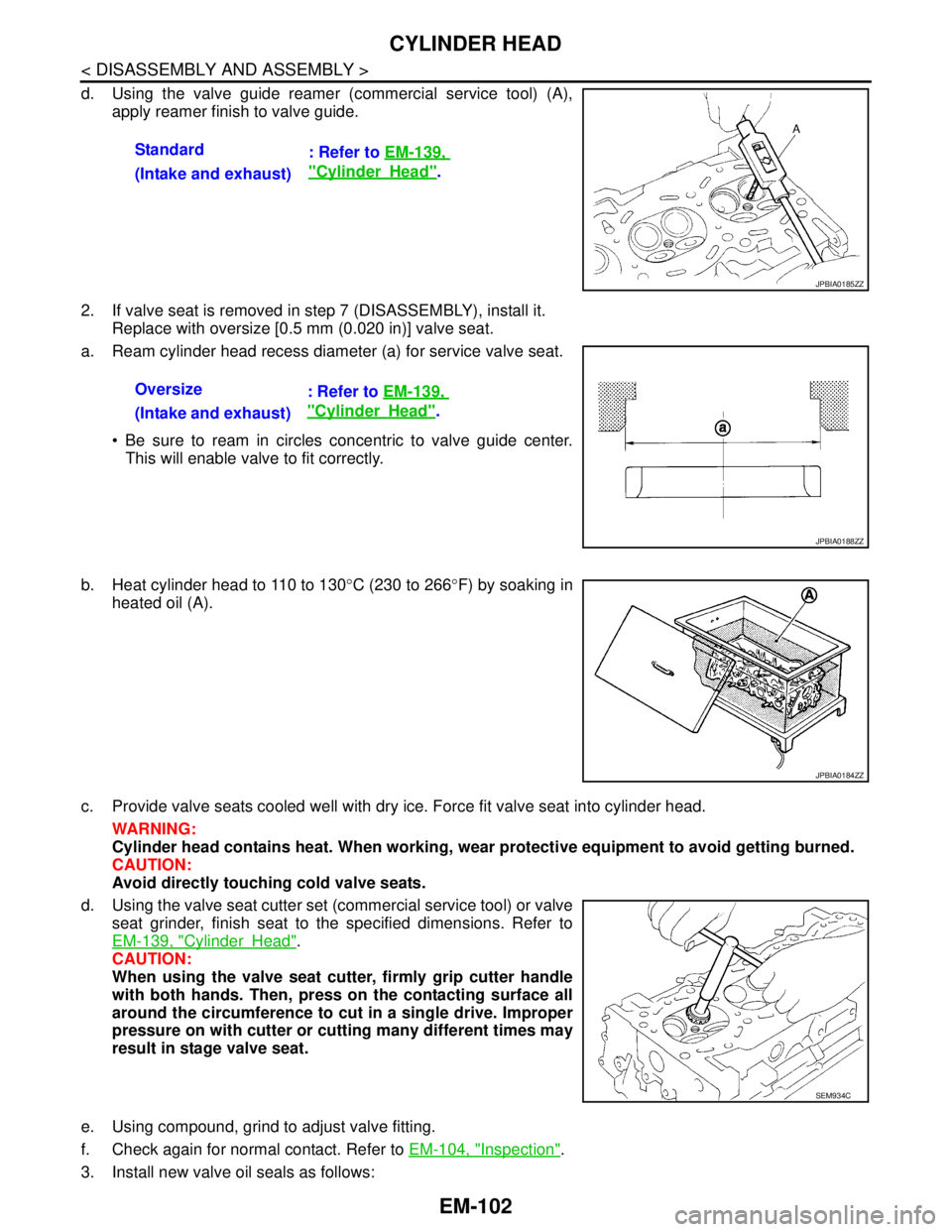
d. Using the valve guide reamer (commercial service tool) (A),
apply reamer finish to valve guide.
2. If valve seat is removed in step 7 (DISASSEMBLY), install it.
Replace with oversize [0.5 mm (0.020 in)] valve seat.
a. Ream cylinder head recess diameter (a) for service valve seat.
Be sure to ream in circles concentric to valve guide center.
This will enable valve to fit correctly.
b. Heat cylinder head to 110 to 130°C (230 to 266°F) by soaking in
heated oil (A).
c. Provide valve seats cooled well with dry ice. Force fit valve seat into cylinder head.
WARNING:
Cylinder head contains heat. When working, wear protective equipment to avoid getting burned.
CAUTION:
Avoid directly touching cold valve seats.
d. Using the valve seat cutter set (commercial service tool) or valve
seat grinder, finish seat to the specified dimensions. Refer to
EM-139, "
CylinderHead".
CAUTION:
When using the valve seat cutter, firmly grip cutter handle
with both hands. Then, press on the contacting surface all
around the circumference to cut in a single drive. Improper
pressure on with cutter or cutting many different times may
result in stage valve seat.
e. Using compound, grind to adjust valve fitting.
f. Check again for normal contact. Refer to EM-104, "
Inspection".
3. Install new valve oil seals as follows:Standard
: Refer to EM-139,
"CylinderHead".
(Intake and exhaust)
JPBIA0185ZZ
Oversize
: Refer to EM-139,
"CylinderHead".
(Intake and exhaust)
JPBIA0188ZZ
JPBIA0184ZZ
SEM934C
Page 1992 of 5121

CYLINDER BLOCK
EM-117
< DISASSEMBLY AND ASSEMBLY >
C
D
E
F
G
H
I
J
K
L
MA
EM
N
P O
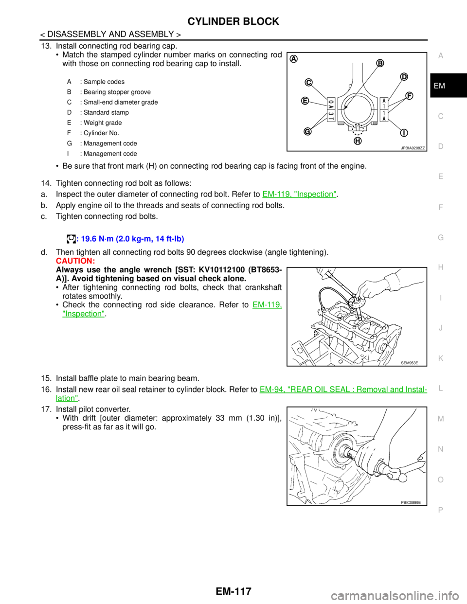
13. Install connecting rod bearing cap.
Match the stamped cylinder number marks on connecting rod
with those on connecting rod bearing cap to install.
Be sure that front mark (H) on connecting rod bearing cap is facing front of the engine.
14. Tighten connecting rod bolt as follows:
a. Inspect the outer diameter of connecting rod bolt. Refer to EM-119, "
Inspection".
b. Apply engine oil to the threads and seats of connecting rod bolts.
c. Tighten connecting rod bolts.
d. Then tighten all connecting rod bolts 90 degrees clockwise (angle tightening).
CAUTION:
Always use the angle wrench [SST: KV10112100 (BT8653-
A)]. Avoid tightening based on visual check alone.
After tightening connecting rod bolts, check that crankshaft
rotates smoothly.
Check the connecting rod side clearance. Refer to EM-119,
"Inspection".
15. Install baffle plate to main bearing beam.
16. Install new rear oil seal retainer to cylinder block. Refer to EM-94, "
REAR OIL SEAL : Removal and Instal-
lation".
17. Install pilot converter.
With drift [outer diameter: approximately 33 mm (1.30 in)],
press-fit as far as it will go.
A: Sample codes
B : Bearing stopper groove
C : Small-end diameter grade
D : Standard stamp
E : Weight grade
F : Cylinder No.
G : Management code
I : Management code
JPBIA0208ZZ
: 19.6 N·m (2.0 kg-m, 14 ft-lb)
SEM953E
PBIC0899E
Page 2394 of 5121

SQUEAK AND RATTLE TROUBLE DIAGNOSES
EXT-5
< SYMPTOM DIAGNOSIS >
C
D
E
F
G
H
I
J
L
MA
B
EXT
N
O
P
Again, pressing on the components to stop the noise while duplicating the conditions can isolate most of these
incidents. Repairs usually consist of insulating with felt cloth tape.
SEATS
When isolating seat noise it is important to note the position the seat is in and the load placed on the seat
when the noise occurs. These conditions must duplicated when verifying and isolating the cause of the noise.
Cause of seat noise include:
1. Headrest rods and holder
2. A squeak between the seat pad cushion and frame
3. Rear seatback lock and bracket
These noises can be isolated by moving or pressing on the suspected components while duplicating the con-
ditions under which the noise occurs. Most of these incidents can be repaired by repositioning the component
or applying urethane tape to the contact area.
UNDERHOOD
Some interior noise may be caused by components under the hood or on the engine wall. The noise is then
transmitted into the passenger compartment.
Causes of transmitted underhood noise include:
1. Any component mounted to the engine wall
2. Components that pass through the engine wall
3. Engine wall mounts and connectors
4. Loose radiator mounting pins
5. Hood bumpers out of adjustment
6. Hood striker out of adjustment
These noises can be difficult to isolate since they cannot be reached from the interior of the vehicle. The best
method is to secure, move or insulate one component at a time and test drive the vehicle. Also, engine RPM
or load can be changed to isolate the noise. Repairs can usually be made by moving, adjusting, securing, or
insulating the component causing the noise.