2008 NISSAN TEANA oil pressure
[x] Cancel search: oil pressurePage 1861 of 5121
![NISSAN TEANA 2008 Service Manual EC-400
< SYMPTOM DIAGNOSIS >[VQ25DE, VQ35DE]
ENGINE CONTROL SYSTEM SYMPTOMS
SYMPTOM DIAGNOSIS
ENGINE CONTROL SYSTEM SYMPTOMS
Symptom TableINFOID:0000000003856875
SYSTEM — BASIC ENGINE CONTROL SYSTEM NISSAN TEANA 2008 Service Manual EC-400
< SYMPTOM DIAGNOSIS >[VQ25DE, VQ35DE]
ENGINE CONTROL SYSTEM SYMPTOMS
SYMPTOM DIAGNOSIS
ENGINE CONTROL SYSTEM SYMPTOMS
Symptom TableINFOID:0000000003856875
SYSTEM — BASIC ENGINE CONTROL SYSTEM](/manual-img/5/57391/w960_57391-1860.png)
EC-400
< SYMPTOM DIAGNOSIS >[VQ25DE, VQ35DE]
ENGINE CONTROL SYSTEM SYMPTOMS
SYMPTOM DIAGNOSIS
ENGINE CONTROL SYSTEM SYMPTOMS
Symptom TableINFOID:0000000003856875
SYSTEM — BASIC ENGINE CONTROL SYSTEM
SYMPTOM
Reference
page
HARD/NO START/RESTART (EXCP. HA)
ENGINE STALL
HESITATION/SURGING/FLAT SPOT
SPARK KNOCK/DETONATION
LACK OF POWER/POOR ACCELERATION
HIGH IDLE/LOW IDLE
ROUGH IDLE/HUNTING
IDLING VIBRATION
SLOW/NO RETURN TO IDLE
OVERHEATS/WATER TEMPERATURE HIGH
EXCESSIVE FUEL CONSUMPTION
EXCESSIVE OIL CONSUMPTION
BATTERY DEAD (UNDER CHARGE)
Warranty symptom code AA AB AC AD AE AF AG AH AJ AK AL AM HA
Fuel Fuel pump circuit 11232 22 3 2EC-337
Fuel pressure regulator system 334444444 4EC-411
Fuel injector circuit 11232 22 2EC-334
Evaporative emission system 334444444 4EC-76
Air Positive crankcase ventilation sys-
tem
334444444 41EC-347
Incorrect idle speed adjustment 1 1 1 1 1EC-11
Electric throttle control actuator 112332222 2 2EC-296,
EC-302
IgnitionIncorrect ignition timing adjustment33111 11 1EC-11
Ignition circuit 11222 22 2EC-341
Power supply and ground circuit 22333 33 23EC-132
Mass air flow sensor circuit
1
122
222 2EC-149
Engine coolant temperature sensor circuit
333EC-157
Air fuel ratio (A/F) sensor 1 circuitEC-163
,
EC-167
,
EC-170
,
EC-173
,
EC-318
Throttle position sensor circuit
22EC-160
,
EC-206
,
EC-254
,
EC-256
,
EC-311
Accelerator pedal position sensor circuit 3 2 1EC-243
,
EC-304
,
EC-307
,
EC-314
Knock sensor circuit 2 3EC-215
Page 1862 of 5121
![NISSAN TEANA 2008 Service Manual ENGINE CONTROL SYSTEM SYMPTOMS
EC-401
< SYMPTOM DIAGNOSIS >[VQ25DE, VQ35DE]
C
D
E
F
G
H
I
J
K
L
MA
EC
N
P O
1 - 6: The numbers refer to the order of inspection.
(continued on the next figure)
SYSTEM � NISSAN TEANA 2008 Service Manual ENGINE CONTROL SYSTEM SYMPTOMS
EC-401
< SYMPTOM DIAGNOSIS >[VQ25DE, VQ35DE]
C
D
E
F
G
H
I
J
K
L
MA
EC
N
P O
1 - 6: The numbers refer to the order of inspection.
(continued on the next figure)
SYSTEM �](/manual-img/5/57391/w960_57391-1861.png)
ENGINE CONTROL SYSTEM SYMPTOMS
EC-401
< SYMPTOM DIAGNOSIS >[VQ25DE, VQ35DE]
C
D
E
F
G
H
I
J
K
L
MA
EC
N
P O
1 - 6: The numbers refer to the order of inspection.
(continued on the next figure)
SYSTEM — ENGINE MECHANICAL & OTHER
Crankshaft position sensor (POS) circuit 2 2EC-218
Camshaft position sensor (PHASE) circuit 3 2EC-222
Vehicle speed signal circuit 2 3 3 3EC-234
Power steering pressure sensor circuit 2 3 3EC-236
ECM 22333333333EC-238,
EC-240
Intake valve timing control solenoid valve cir-
cuit32 13223 3EC-146
PNP signal circuit 3 3 3 3 3EC-245
VIAS control solenoid valve 1 circuit 1EC-285
VIAS control solenoid valve 2 circuit 1EC-288
Refrigerant pressure sensor circuit 2 3 3 4EC-348
Electrical load signal circuit 3EC-329
Air conditioner circuit 223333333 3 2HAC-159
ABS actuator and electric unit (control unit) 4BRC-80
SYMPTOM
Reference
page
HARD/NO START/RESTART (EXCP. HA)
ENGINE STALL
HESITATION/SURGING/FLAT SPOT
SPARK KNOCK/DETONATION
LACK OF POWER/POOR ACCELERATION
HIGH IDLE/LOW IDLE
ROUGH IDLE/HUNTING
IDLING VIBRATION
SLOW/NO RETURN TO IDLE
OVERHEATS/WATER TEMPERATURE HIGH
EXCESSIVE FUEL CONSUMPTION
EXCESSIVE OIL CONSUMPTION
BATTERY DEAD (UNDER CHARGE)
Warranty symptom code AA AB AC AD AE AF AG AH AJ AK AL AM HA
Page 1876 of 5121
EM-1
ENGINE
C
D
E
F
G
H
I
J
K
L
M
SECTION EM
A
EM
N
O
P
CONTENTS
ENGINE MECHANICAL
SYMPTOM DIAGNOSIS ...............................3
NOISE, VIBRATION AND HARSHNESS
(NVH) TROUBLESHOOTING .............................
3
NVH Troubleshooting - Engine Noise .......................3
Use the Chart Below to Help You Find the Cause
of the Symptom .........................................................
4
PRECAUTION ...............................................5
PRECAUTIONS ...................................................5
Precaution for Procedure without Cowl Top Cover ......5
Precaution for Supplemental Restraint System
(SRS) "AIR BAG" and "SEAT BELT PRE-TEN-
SIONER" ...................................................................
5
Precaution Necessary for Steering Wheel Rota-
tion after Battery Disconnect .....................................
5
Precaution for Drain Engine Coolant and Engine
Oil ..............................................................................
6
Precaution for Disconnecting Fuel Piping .................6
Precaution for Removal and Disassembly ................6
Precaution for Inspection, Repair and Replace-
ment ..........................................................................
6
Precaution for Assembly and Installation ..................6
Precaution for Angle Tightening ................................6
Precaution for Liquid Gasket .....................................7
PREPARATION ............................................8
PREPARATION ...................................................8
Special Service Tool .................................................8
Commercial Service Tool ..........................................9
ON-VEHICLE MAINTENANCE ....................12
DRIVE BELT .......................................................12
Exploded View ........................................................12
Checking .................................................................12
Tension Adjustment ................................................12
Removal and Installation .........................................12
AIR CLEANER FILTER ......................................14
Removal and Installation .........................................14
SPARK PLUG ...................................................15
Exploded View .........................................................15
Removal and Installation .........................................15
Inspection ................................................................16
CAMSHAFT VALVE CLEARANCE ..................17
Inspection and Adjustment ......................................17
COMPRESSION PRESSURE ...........................22
Inspection ................................................................22
ON-VEHICLE REPAIR .................................24
ENGINE COVER ...............................................24
Exploded View .........................................................24
Removal and Installation .........................................24
DRIVE BELT AUTO TENSIONER AND IDLER
PULLEY .............................................................
25
Exploded View .........................................................25
Removal and Installation .........................................25
AIR CLEANER AND AIR DUCT .......................26
Exploded View .........................................................26
Removal and Installation .........................................26
Inspection ................................................................27
INTAKE MANIFOLD COLLECTOR ..................28
Exploded View .........................................................28
Removal and Installation .........................................29
INTAKE MANIFOLD .........................................32
Exploded View .........................................................32
Removal and Installation .........................................32
Inspection ................................................................33
EXHAUST MANIFOLD AND THREE WAY
CATALYST ........................................................
34
Exploded View .........................................................34
Removal and Installation .........................................34
Inspection ................................................................37
Page 1881 of 5121

EM-6
< PRECAUTION >
PRECAUTIONS
3. Disconnect both battery cables. The steering lock will remain released with both battery cables discon-
nected and the steering wheel can be turned.
4. Perform the necessary repair operation.
5. When the repair work is completed, re-connect both battery cables. With the brake pedal released, turn
the push-button ignition switch from ACC position to ON position, then to LOCK position. (The steering
wheel will lock when the push-button ignition switch is turned to LOCK position.)
6. Perform self-diagnosis check of all control units using CONSULT-III.
Precaution for Drain Engine Coolant and Engine OilINFOID:0000000003802227
Drain engine coolant and engine oil when the engine is cooled.
Precaution for Disconnecting Fuel PipingINFOID:0000000003802228
Before starting work, check no fire or spark producing items are in the work area.
Release fuel pressure before disconnecting and disassembly.
After disconnecting pipes, plug openings to stop fuel leakage.
Precaution for Removal and DisassemblyINFOID:0000000003802229
When instructed to use SST, use the specified tools. Always be careful to work safely, avoid forceful or unin-
structed operations.
Exercise maximum care to avoid damage to mating or sliding surfaces.
Dowel pins are used for several parts alignment. When replacing and reassembling parts with dowel pins,
check that dowel pins are installed in the original position.
Cover openings of engine system with a tape or the equivalent, if necessary, to seal out foreign materials.
Mark and arrange disassembly parts in an organized way for easy troubleshooting and reassembly.
When loosening nuts and bolts, as a basic rule, start with the one furthest outside, then the one diagonally
opposite, and so on. If the order of loosening is specified, do exactly as specified. Power tools may be used
in the step.
Precaution for Inspection, Repair and ReplacementINFOID:0000000003802230
Before repairing or replacing, thoroughly inspect parts. Inspect new replacement parts in the same way, and
replace if necessary.
Precaution for Assembly and InstallationINFOID:0000000003802231
Use torque wrench to tighten bolts or nuts to specification.
When tightening nuts and bolts, as a basic rule, equally tighten in several different steps starting with the
ones in center, then ones on inside and outside diagonally in this order. If the order of tightening is specified,
do exactly as specified.
Replace with new gasket, packing, oil seal or O-ring.
Dowel pins are used for several parts alignment. When replacing and reassembling parts with dowel pins,
check that dowel pins are installed in the original position.
Thoroughly wash, clean, and air-blow each part. Carefully check engine oil or engine coolant passages for
any restriction and blockage.
Avoid damaging sliding or mating surfaces. Completely remove foreign materials such as cloth lint or dust.
Before assembly, oil sliding surfaces well.
Release air within route when refilling after draining engine coolant.
After repairing, start the engine and increase engine speed to check engine coolant, fuel, engine oil, and
exhaust gases for leakage.
Precaution for Angle TighteningINFOID:0000000003802232
Use the angle wrench [SST: KV10112100 (BT8653-A)] for the final tightening of the following engine parts:
- Cylinder head bolts
- Main bearing cap bolts
- Connecting rod cap bolts
- Crankshaft pulley bolt (No the angle wrench is required as bolt flange is provided with notches for angle
tightening)
Never use a torque value for final tightening.
The torque value for these parts are for a preliminary step.
Page 1897 of 5121
EM-22
< ON-VEHICLE MAINTENANCE >
COMPRESSION PRESSURE
COMPRESSION PRESSURE
InspectionINFOID:0000000003802245
1. Warm up engine thoroughly. Then, stop it.
2. Release fuel pressure. Refer to EC-411, "
Inspection".
3. Disconnect fuel pump fuse to avoid fuel injection during measurement. Refer to EC-20,
"ComponentPartsLocation".
4. Remove engine cover. Refer to EM-24, "
Exploded View".
5. Remove ignition coil and spark plug from each cylinder. Refer to EM-49, "
Exploded View".
6. Connect engine tachometer (not required in use of CONSULT-III).
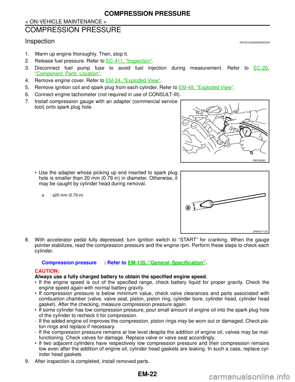
7. Install compression gauge with an adapter (commercial service
tool) onto spark plug hole.
Use the adapter whose picking up end inserted to spark plug
hole is smaller than 20 mm (0.79 in) in diameter. Otherwise, it
may be caught by cylinder head during removal.
8. With accelerator pedal fully depressed, turn ignition switch to “START” for cranking. When the gauge
pointer stabilizes, read the compression pressure and the engine rpm. Perform these steps to check each
cylinder.
CAUTION:
Always use a fully charged battery to obtain the specified engine speed.
If the engine speed is out of the specified range, check battery liquid for proper gravity. Check the
engine speed again with normal battery gravity.
If compression pressure is below minimum value, check valve clearances and parts associated with
combustion chamber (valve, valve seat, piston, piston ring, cylinder bore, cylinder head, cylinder head
gasket). After the checking, measure compression pressure again.
If some cylinder has low compression pressure, pour small amount of engine oil into the spark plug hole
of the cylinder to recheck it for compression.
- If the added engine oil improves the compression, piston rings may be worn out or damaged. Check pis-
ton rings and replace if necessary.
- If the compression pressure remains at low level despite the addition of engine oil, valves may be mal-
functioning. Check valves for damage. Replace valve or valve seat accordingly.
If two adjacent cylinders have respectively low compression pressure and their compression remains
low even after the addition of engine oil, cylinder head gaskets are leaking. In such a case, replace cyl-
inder head gaskets.
9. After inspection is completed, install removed parts.
PBIC0900E
a: φ20 mm (0.79 in)
JPBIA0171ZZ
Compression pressure : Refer to EM-135, "GeneralSpecification".
Page 1913 of 5121
EM-38
< ON-VEHICLE REPAIR >
OIL PAN AND OIL STRAINER
OIL PAN AND OIL STRAINER
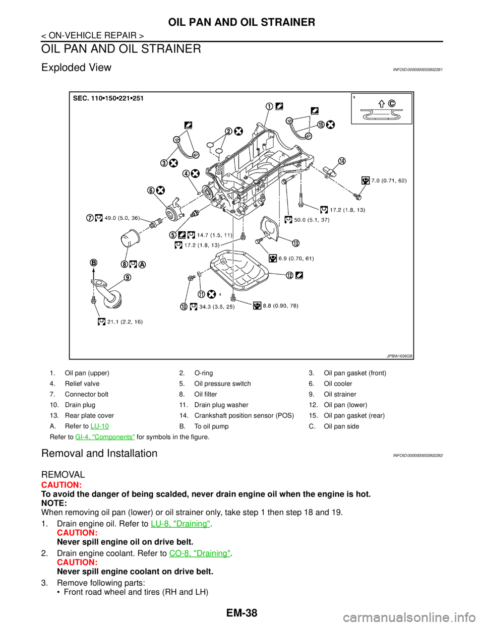
Exploded ViewINFOID:0000000003802261
Removal and InstallationINFOID:0000000003802262
REMOVAL
CAUTION:
To avoid the danger of being scalded, never drain engine oil when the engine is hot.
NOTE:
When removing oil pan (lower) or oil strainer only, take step 1 then step 18 and 19.
1. Drain engine oil. Refer to LU-8, "
Draining".
CAUTION:
Never spill engine oil on drive belt.
2. Drain engine coolant. Refer to CO-8, "
Draining".
CAUTION:
Never spill engine coolant on drive belt.
3. Remove following parts:
Front road wheel and tires (RH and LH)
1. Oil pan (upper) 2. O-ring 3. Oil pan gasket (front)
4. Relief valve 5. Oil pressure switch 6. Oil cooler
7. Connector bolt 8. Oil filter 9. Oil strainer
10. Drain plug 11. Drain plug washer 12. Oil pan (lower)
13. Rear plate cover 14. Crankshaft position sensor (POS) 15. Oil pan gasket (rear)
A. Refer to LU-10
B. To oil pump C. Oil pan side
Refer to GI-4, "
Components" for symbols in the figure.
JPBIA1636GB
Page 1914 of 5121
OIL PAN AND OIL STRAINER
EM-39
< ON-VEHICLE REPAIR >
C
D
E
F
G
H
I
J
K
L
MA
EM
N
P O
Splash guard (RH and LH): Refer to EXT-22, "FENDER PROTECTOR : Exploded View".
Exhaust front tube: Refer to EX-5, "
Exploded View".
Drive belt: Refer to EM-12, "
Removal and Installation".
4. Remove A/C compressor with piping connected, and temporarily secure it to aside. Refer to HA-36,
"Exploded View".
5. Remove oil level gauge. Refer to EM-96, "
Exploded View".
6. Remove front drive shaft (RH). Refer to FAX-16, "
Exploded View".
7. Remove three way catalyst (bank 1 and bank 2) from exhaust manifolds (bank 1 and bank 2). Refer to
EM-34, "
Exploded View".
8. Remove oil pressure switch.
9. Remove oil filter. Refer to LU-10, "
Removal and Installation".
10. Remove oil cooler and water pipes. Refer to LU-11, "
Exploded View".
11. Support transaxle assembly with a suitable jack.
CAUTION:
When setting the transmission jack, be careful not to allow it to collide against the drain plug.
12. Support front suspension member with a suitable jack.
13. Remove engine mounting insulator (rear). Refer to EM-67, "
Exploded View".
14. Remove engine mounting insulator (LH) mounting bolts from transaxle. Refer to EM-67, "
Exploded View".
15. Remove rear torque rod through bolts from rear torque rod bracket. Refer to EM-67, "
Exploded View".
16. Remove member stay, front suspension member fixing bolts and nuts. Refer to FSU-16, "
Exploded View".
17. Lower the jack for the front suspension member to the height.
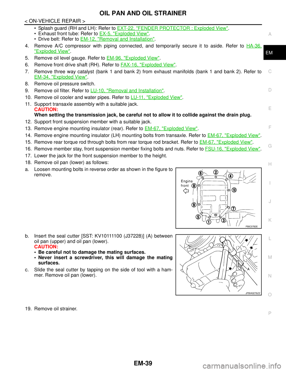
18. Remove oil pan (lower) as follows:
a. Loosen mounting bolts in reverse order as shown in the figure to
remove.
b. Insert the seal cutter [SST: KV10111100 (J37228)] (A) between
oil pan (upper) and oil pan (lower).
CAUTION:
Be careful not to damage the mating surfaces.
Never insert a screwdriver, this will damage the mating
surfaces.
c. Slide the seal cutter by tapping on the side of tool with a ham-
mer. Remove oil pan (lower).
19. Remove oil strainer.
PBIC0782E
JPBIA0276ZZ
Page 1921 of 5121
EM-46
< ON-VEHICLE REPAIR >
FUEL INJECTOR AND FUEL TUBE
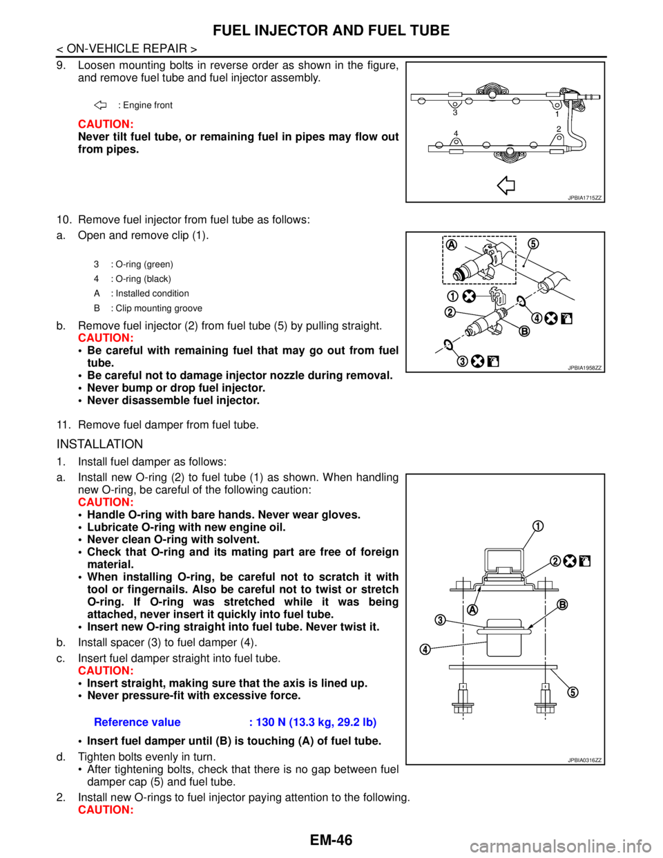
9. Loosen mounting bolts in reverse order as shown in the figure,
and remove fuel tube and fuel injector assembly.
CAUTION:
Never tilt fuel tube, or remaining fuel in pipes may flow out
from pipes.
10. Remove fuel injector from fuel tube as follows:
a. Open and remove clip (1).
b. Remove fuel injector (2) from fuel tube (5) by pulling straight.
CAUTION:
Be careful with remaining fuel that may go out from fuel
tube.
Be careful not to damage injector nozzle during removal.
Never bump or drop fuel injector.
Never disassemble fuel injector.
11. Remove fuel damper from fuel tube.
INSTALLATION
1. Install fuel damper as follows:
a. Install new O-ring (2) to fuel tube (1) as shown. When handling
new O-ring, be careful of the following caution:
CAUTION:
Handle O-ring with bare hands. Never wear gloves.
Lubricate O-ring with new engine oil.
Never clean O-ring with solvent.
Check that O-ring and its mating part are free of foreign
material.
When installing O-ring, be careful not to scratch it with
tool or fingernails. Also be careful not to twist or stretch
O-ring. If O-ring was stretched while it was being
attached, never insert it quickly into fuel tube.
Insert new O-ring straight into fuel tube. Never twist it.
b. Install spacer (3) to fuel damper (4).
c. Insert fuel damper straight into fuel tube.
CAUTION:
Insert straight, making sure that the axis is lined up.
Never pressure-fit with excessive force.
Insert fuel damper until (B) is touching (A) of fuel tube.
d. Tighten bolts evenly in turn.
After tightening bolts, check that there is no gap between fuel
damper cap (5) and fuel tube.
2. Install new O-rings to fuel injector paying attention to the following.
CAUTION:
: Engine front
JPBIA1715ZZ
3 : O-ring (green)
4 : O-ring (black)
A : Installed condition
B : Clip mounting groove
JPBIA1958ZZ
Reference value : 130 N (13.3 kg, 29.2 lb)
JPBIA0316ZZ