2008 NISSAN TEANA oil pressure
[x] Cancel search: oil pressurePage 2249 of 5121
![NISSAN TEANA 2008 Service Manual EXL-220
< FUNCTION DIAGNOSIS >[HALOGEN TYPE]
DIAGNOSIS SYSTEM (IPDM E/R)
Concept of auto active test
IPDM E/R starts the auto active test with the door switch signals transmitted by BCM via CAN comm NISSAN TEANA 2008 Service Manual EXL-220
< FUNCTION DIAGNOSIS >[HALOGEN TYPE]
DIAGNOSIS SYSTEM (IPDM E/R)
Concept of auto active test
IPDM E/R starts the auto active test with the door switch signals transmitted by BCM via CAN comm](/manual-img/5/57391/w960_57391-2248.png)
EXL-220
< FUNCTION DIAGNOSIS >[HALOGEN TYPE]
DIAGNOSIS SYSTEM (IPDM E/R)
Concept of auto active test
IPDM E/R starts the auto active test with the door switch signals transmitted by BCM via CAN communica-
tion. Therefore, the CAN communication line between IPDM E/R and BCM is considered normal if the auto
active test starts successfully.
The auto active test facilitates troubleshooting if any systems controlled by IPDM E/R cannot be operated.
Diagnosis chart in auto active test mode
JPMIA1016GB
Symptom Inspection contents Possible cause
Any of the following components do not operate
Parking lamps
License plate lamps
Tail lamps
Front fog lamps
Headlamp (HI, LO)
Front wiperPerform auto active test.
Does the applicable system
operate?YES BCM signal input circuit
NO Lamp or motor
Lamp or motor ground cir-
cuit
Harness or connector be-
tween IPDM E/R and appli-
cable system
IPDM E/R
A/C compressor does not operatePerform auto active test.
Does the magnet clutch oper-
ate?YES A/C amp. signal input circuit
CAN communication signal
between A/C amp. and
ECM
CAN communication signal
between ECM and IPDM E/
R
NO Magnet clutch
Harness or connector be-
tween IPDM E/R and mag-
net clutch
IPDM E/R
Oil pressure warning lamp does not operatePerform auto active test.
Does the oil pressure warning
lamp blink?YES Harness or connector be-
tween IPDM E/R and oil
pressure switch
Oil pressure switch
IPDM E/R
NO CAN communication signal
between IPDM E/R and
BCM
CAN communication signal
between BCM and combi-
nation meter
Combination meter
Page 2251 of 5121
![NISSAN TEANA 2008 Service Manual EXL-222
< FUNCTION DIAGNOSIS >[HALOGEN TYPE]
DIAGNOSIS SYSTEM (IPDM E/R)
ACTIVE TEST
Te s t i t e m
IGN RLY
[Off/On]×Displays the status of the ignition relay judged by IPDM E/R.
PUSH SW
[Off/On]Dis NISSAN TEANA 2008 Service Manual EXL-222
< FUNCTION DIAGNOSIS >[HALOGEN TYPE]
DIAGNOSIS SYSTEM (IPDM E/R)
ACTIVE TEST
Te s t i t e m
IGN RLY
[Off/On]×Displays the status of the ignition relay judged by IPDM E/R.
PUSH SW
[Off/On]Dis](/manual-img/5/57391/w960_57391-2250.png)
EXL-222
< FUNCTION DIAGNOSIS >[HALOGEN TYPE]
DIAGNOSIS SYSTEM (IPDM E/R)
ACTIVE TEST
Te s t i t e m
IGN RLY
[Off/On]×Displays the status of the ignition relay judged by IPDM E/R.
PUSH SW
[Off/On]Displays the status of the push-button ignition switch judged by IPDM E/R.
INTER/NP SW
[Off/On]Displays the status of the shift position judged by IPDM E/R.
ST RLY CONT
[Off/On]Displays the status of the starter relay status signal received from BCM via CAN
communication.
IHBT RLY -REQ
[Off/On]Displays the status of the starter control relay signal received from BCM via CAN
communication.
ST/INHI RLY
[Off/ ST /INHI/UNKWN]Displays the status of the starter relay and starter control relay judged by IPDM
E/R.
DETENT SW
[Off/On]Displays the status of the control device (detention switch) judged by IPDM E/R.
S/L RLY -REQ
[Off/On]Displays the status of the steering lock relay signal received from BCM via CAN
communication.
S/L STATE
[LOCK/UNLOCK/UNKWN]Displays the status of the steering lock judged by IPDM E/R.
DTRL REQ
[Off]NOTE:
The item is indicated, but not monitored.
OIL P SW
[Open/Close]Displays the status of the oil pressure switch judged by IPDM E/R.
HOOD SW
[Off/On]Displays the status of the hood switch judged by IPDM E/R.
HL WASHER REQ
[Off]Display the status of the headlamp washer request signal received from BCM via
CAN communication.
THFT HRN REQ
[Off/On]Displays the status of the theft warning horn request signal received from BCM
via CAN communication.
HORN CHIRP
[Off/On]Displays the status of the horn reminder signal received from BCM via CAN com-
munication.
CRNRNG LMP REQ
[Off]NOTE:
The item is indicated, but not monitored. Monitor Item
[Unit]MAIN SIG-
NALSDescription
Test item Operation Description
CORNERING LAMPOff
NOTE:
The item is indicated, but cannot be tested. LH
RH
HORN On Operates horn relay for 20 ms.
FRONT WIPEROff OFF
Lo Operates the front wiper relay.
Hi Operates the front wiper relay and front wiper high relay.
MOTOR FAN1OFF
2 Operates the cooling fan relay-1.
3 Operates the cooling fan relay-2.
4 Operates the cooling fan relay-2 and cooling fan relay-3.
HEAD LAMP WASHER On Operates the headlamp washer relay for 1 s.
Page 2349 of 5121
![NISSAN TEANA 2008 Service Manual EXL-320
< ECU DIAGNOSIS >[HALOGEN TYPE]
IPDM E/R (INTELLIGENT POWER DISTRIBUTION MODULE ENGINE ROOM)
75
(P/L)Ground Oil pressure switch InputIgnition
switch ONEngine stopped 0 V
Engine running Batter NISSAN TEANA 2008 Service Manual EXL-320
< ECU DIAGNOSIS >[HALOGEN TYPE]
IPDM E/R (INTELLIGENT POWER DISTRIBUTION MODULE ENGINE ROOM)
75
(P/L)Ground Oil pressure switch InputIgnition
switch ONEngine stopped 0 V
Engine running Batter](/manual-img/5/57391/w960_57391-2348.png)
EXL-320
< ECU DIAGNOSIS >[HALOGEN TYPE]
IPDM E/R (INTELLIGENT POWER DISTRIBUTION MODULE ENGINE ROOM)
75
(P/L)Ground Oil pressure switch InputIgnition
switch ONEngine stopped 0 V
Engine running Battery voltage
76
(SB)GroundPower generation com-
mand signalOutputIgnition switch ON
6.3 V
40% is set on “ACTIVE TEST”, “AL-
TERNATOR DUTY” of “ENGINE”
3.8 V
80% is set on “ACTIVE TEST”, “AL-
TERNATOR DUTY” of “ENGINE”
1.4 V
77
(GR)Ground Fuel pump relay control Output Approximately 1 second after turning
the ignition switch ON
Engine running0 - 1.5 V
Approximately 1 second or more after
turning the ignition switch ONBattery voltage
80
(B/W)Ground Starter motor Output At engine cranking Battery voltage
83
(Y)Ground Headlamp LO (RH) OutputIgnition
switch ONLighting switch OFF 0 V
Lighting switch 2ND Battery voltage
84
(SB)Ground Headlamp LO (LH) OutputIgnition
switch ONLighting switch OFF 0 V
Lighting switch 2ND Battery voltage
86
(L)Ground Front fog lamp (RH) OutputLighting
switch
2ND Front fog lamp switch
ON
Daytime running light
activated (Only for Can-
ada)Battery voltage
Front fog lamp switch OFF 0 V
87
(R)Ground Front fog lamp (LH) OutputLighting
switch
2ND Front fog lamp switch
ON
Daytime running light
activated (Only for Can-
ada)Battery voltage
Front fog lamp switch OFF 0 V Te r m i n a l N o .
(Wire color)Description
ConditionVa l u e
(Approx.)
Signal nameInput/
Output +−
JPMIA0001GB
JPMIA0002GB
JPMIA0003GB
Page 2365 of 5121
![NISSAN TEANA 2008 Service Manual EXL-336
< ON-VEHICLE MAINTENANCE >[HALOGEN TYPE]
HEADLAMP AIMING ADJUSTMENT
ON-VEHICLE MAINTENANCE
HEADLAMP AIMING ADJUSTMENT
DescriptionINFOID:0000000003829238
PREPARATION BEFORE ADJUSTING
NOTE:
Fo NISSAN TEANA 2008 Service Manual EXL-336
< ON-VEHICLE MAINTENANCE >[HALOGEN TYPE]
HEADLAMP AIMING ADJUSTMENT
ON-VEHICLE MAINTENANCE
HEADLAMP AIMING ADJUSTMENT
DescriptionINFOID:0000000003829238
PREPARATION BEFORE ADJUSTING
NOTE:
Fo](/manual-img/5/57391/w960_57391-2364.png)
EXL-336
< ON-VEHICLE MAINTENANCE >[HALOGEN TYPE]
HEADLAMP AIMING ADJUSTMENT
ON-VEHICLE MAINTENANCE
HEADLAMP AIMING ADJUSTMENT
DescriptionINFOID:0000000003829238
PREPARATION BEFORE ADJUSTING
NOTE:
For details, refer to the regulations in your own country.
Perform aiming if the vehicle front body has been repaired and/or the headlamp assembly has been
replaced.
Before performing aiming adjustment, check the following. Adjust the tire pressure to the specification.
Fill with fuel, engine coolant and each oil.
Maintain the unloaded vehicle condition. (Remove luggage from the passenger compartment and the trunk
room.)
NOTE:
Do not remove the temporary tire, jack and on-vehicle tool.
Wipe out dirt on the headlamp.
CAUTION:
Never use organic solvent (thinner, gasoline etc.)
Ride alone on the driver seat.
Headlamp aiming switch sets to “0”.
AIMING ADJUSTMENT SCREW
JPLIA1104ZZ
Page 2370 of 5121
![NISSAN TEANA 2008 Service Manual FRONT FOG LAMP AIMING ADJUSTMENT
EXL-341
< ON-VEHICLE MAINTENANCE >[HALOGEN TYPE]
C
D
E
F
G
H
I
J
K
MA
B
EXL
N
O
P
FRONT FOG LAMP AIMING ADJUSTMENT
DescriptionINFOID:0000000003894358
PREPARATION BEFOR NISSAN TEANA 2008 Service Manual FRONT FOG LAMP AIMING ADJUSTMENT
EXL-341
< ON-VEHICLE MAINTENANCE >[HALOGEN TYPE]
C
D
E
F
G
H
I
J
K
MA
B
EXL
N
O
P
FRONT FOG LAMP AIMING ADJUSTMENT
DescriptionINFOID:0000000003894358
PREPARATION BEFOR](/manual-img/5/57391/w960_57391-2369.png)
FRONT FOG LAMP AIMING ADJUSTMENT
EXL-341
< ON-VEHICLE MAINTENANCE >[HALOGEN TYPE]
C
D
E
F
G
H
I
J
K
MA
B
EXL
N
O
P
FRONT FOG LAMP AIMING ADJUSTMENT
DescriptionINFOID:0000000003894358
PREPARATION BEFORE ADJUSTING
NOTE:
For details, refer to the regulations in your own country.
Before performing aiming adjustment, check the following.
Adjust the tire pressure to the specification.
Fill with fuel, engine coolant and each oil.
Maintain the unloaded vehicle condition. (Remove luggage from the passenger compartment and the lug-
gage room.)
NOTE:
Do not remove the temporary tire, jack and on-vehicle tool.
Wipe out dirt on the headlamp.
CAUTION:
Never use organic solvent (thinner, gasoline etc.)
Ride alone on the driver seat.
AIMING ADJUSTMENT SCREW
Turn the aiming adjusting screw for adjustment.
For the position and direction of the adjusting screw, refer to the
figure.
NOTE:
A screwdriver or hexagonal wrench [6 mm (0.24 in)] can be used
for adjustment.
Aiming Adjustment ProcedureINFOID:0000000003894359
1. Place the screen.
NOTE:
Stop the vehicle facing the wall.
Place the board on a plain road vertically.
2. Face the vehicle with the screen. Maintain 10 m (32.8 ft) between the front fog lamp center and the
screen.
3. Start the engine. Illuminate the front fog lamp.
CAUTION:
Never cover the lens surface with a tape etc. The lens is made of resin.
NOTE:
Shut off the headlamp light with the board to prevent from illuminating the adjustment screen.
4. Adjust the cutoff line height (A) with the aiming adjustment screw so that the distance (X) between the hor-
izontal center line of front fog lamp (H) and (A) becomes 200 mm (7.87 in).
Front fog lamp light distribution on the screen
A: UP
B: DOWN
JPLIA1086ZZ
JPLIA0008ZZ
Page 2490 of 5121

FSU-16
< REMOVAL AND INSTALLATION >
FRONT SUSPENSION MEMBER
REMOVAL AND INSTALLATION
FRONT SUSPENSION MEMBER
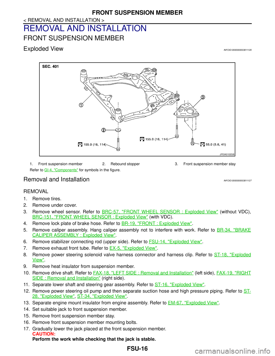
Exploded ViewINFOID:0000000003811126
Removal and InstallationINFOID:0000000003811127
REMOVAL
1. Remove tires.
2. Remove under cover.
3. Remove wheel sensor. Refer to BRC-57, "
FRONT WHEEL SENSOR : Exploded View" (without VDC),
BRC-151, "
FRONT WHEEL SENSOR : Exploded View" (with VDC).
4. Remove lock plate of brake hose. Refer to BR-19, "
FRONT : Exploded View".
5. Remove caliper assembly. Hang caliper assembly not to interfere with work. Refer to BR-34, "
BRAKE
CALIPER ASSEMBLY : Exploded View".
6. Remove stabilizer connecting rod (upper side). Refer to FSU-14, "
Exploded View".
7. Remove exhaust front tube. Refer to EX-5, "
Exploded View".
8. Remove power steering solenoid valve harness connector and harness clip. Refer to ST-18, "
Exploded
View".
9. Remove heat insulator from suspension member.
10. Remove drive shaft. Refer to FAX-18, "
LEFT SIDE : Removal and Installation" (left side), FAX-19, "RIGHT
SIDE : Removal and Installation" (right side).
11. Separate lower shaft and steering gear assembly. Refer to ST-16, "
Exploded View".
12. Remove power steering oil pump and then separate suction hose and high pressure piping. Refer to ST-
28, "Exploded View", ST-34, "Exploded View".
13. Separate engine mount insulator from engine assembly. Refer to EM-67, "
Exploded View".
14. Set suitable jack to front suspension member.
15. Remove front suspension member stay.
16. Remove front suspension member mounting bolts.
17. Gradually lower the jack placed at the front suspension member.
CAUTION:
Perform the work while checking that the jack is stable.
1. Front suspension member 2. Rebound stopper 3. Front suspension member stay
Refer to GI-4, "
Components" for symbols in the figure.
JPEIA0102GB
Page 2580 of 5121

COMPRESSOR SYSTEM SYMPTOMS
HA-11
< SYMPTOM DIAGNOSIS >
C
D
E
F
G
H
J
K
L
MA
B
HA
N
O
P
COMPRESSOR SYSTEM SYMPTOMS
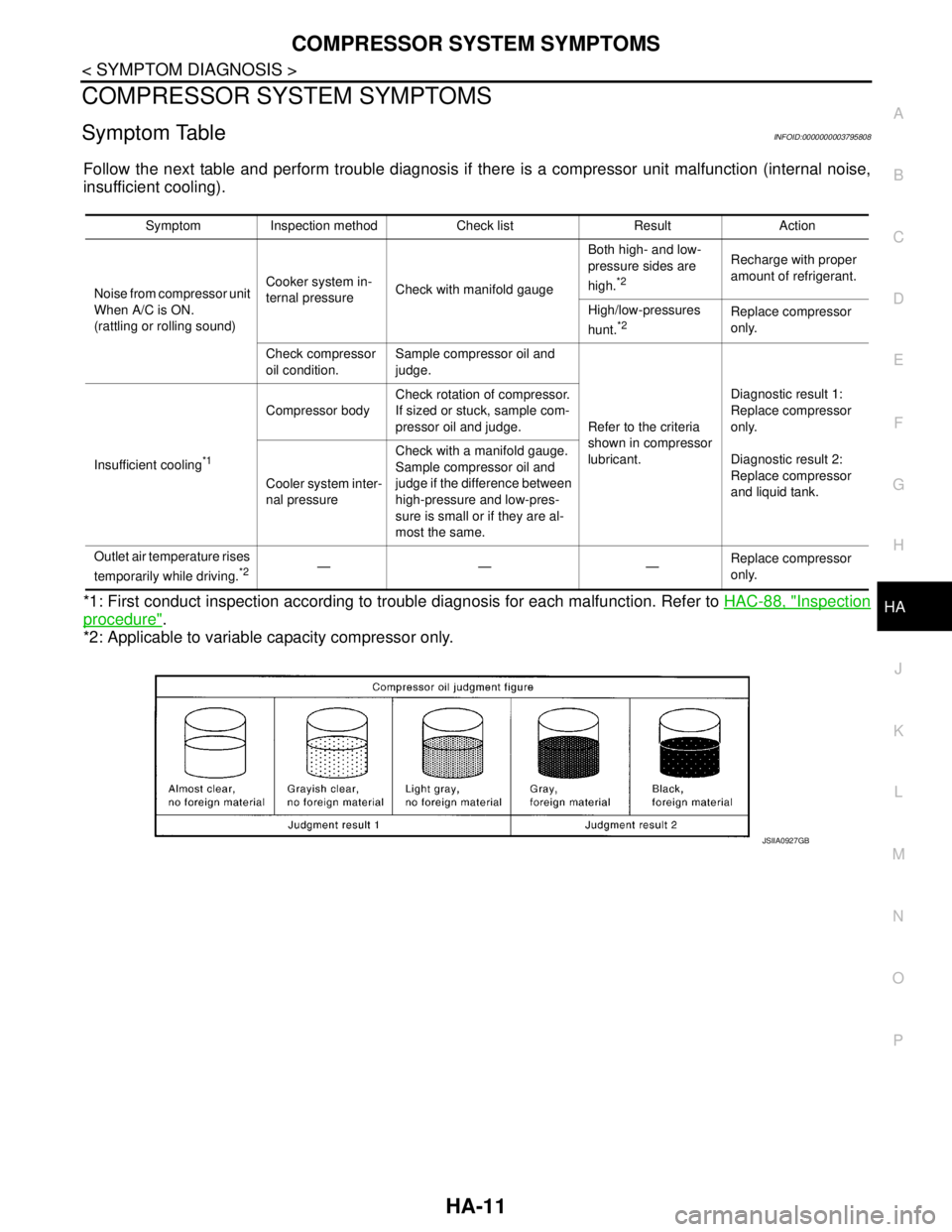
Symptom TableINFOID:0000000003795808
Follow the next table and perform trouble diagnosis if there is a compressor unit malfunction (internal noise,
insufficient cooling).
*1: First conduct inspection according to trouble diagnosis for each malfunction. Refer to HAC-88, "
Inspection
procedure".
*2: Applicable to variable capacity compressor only.
Symptom Inspection method Check list Result Action
Noise from compressor unit
When A/C is ON.
(rattling or rolling sound)Cooker system in-
ternal pressureCheck with manifold gaugeBoth high- and low-
pressure sides are
high.
*2
Recharge with proper
amount of refrigerant.
High/low-pressures
hunt.
*2Replace compressor
only.
Check compressor
oil condition.Sample compressor oil and
judge.
Refer to the criteria
shown in compressor
lubricant.Diagnostic result 1:
Replace compressor
only.
Diagnostic result 2:
Replace compressor
and liquid tank. Insufficient cooling
*1
Compressor bodyCheck rotation of compressor.
If sized or stuck, sample com-
pressor oil and judge.
Cooler system inter-
nal pressureCheck with a manifold gauge.
Sample compressor oil and
judge if the difference between
high-pressure and low-pres-
sure is small or if they are al-
most the same.
Outlet air temperature rises
temporarily while driving.
*2—— —Replace compressor
only.
JSIIA0927GB
Page 2584 of 5121

PRECAUTIONS
HA-15
< PRECAUTION >
C
D
E
F
G
H
J
K
L
MA
B
HA
N
O
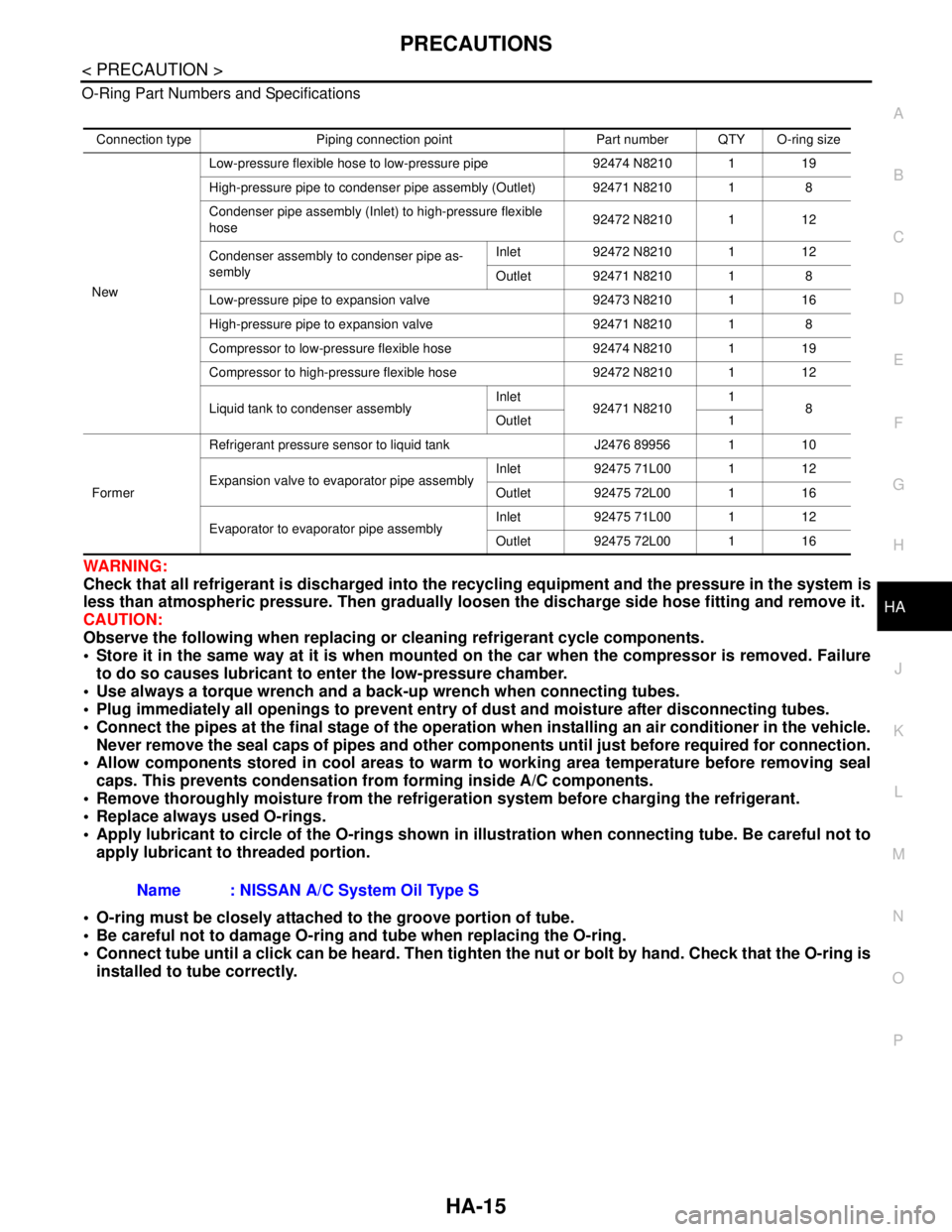
P O-Ring Part Numbers and Specifications
WARNING:
Check that all refrigerant is discharged into the recycling equipment and the pressure in the system is
less than atmospheric pressure. Then gradually loosen the discharge side hose fitting and remove it.
CAUTION:
Observe the following when replacing or cleaning refrigerant cycle components.
Store it in the same way at it is when mounted on the car when the compressor is removed. Failure
to do so causes lubricant to enter the low-pressure chamber.
Use always a torque wrench and a back-up wrench when connecting tubes.
Plug immediately all openings to prevent entry of dust and moisture after disconnecting tubes.
Connect the pipes at the final stage of the operation when installing an air conditioner in the vehicle.
Never remove the seal caps of pipes and other components until just before required for connection.
Allow components stored in cool areas to warm to working area temperature before removing seal
caps. This prevents condensation from forming inside A/C components.
Remove thoroughly moisture from the refrigeration system before charging the refrigerant.
Replace always used O-rings.
Apply lubricant to circle of the O-rings shown in illustration when connecting tube. Be careful not to
apply lubricant to threaded portion.
O-ring must be closely attached to the groove portion of tube.
Be careful not to damage O-ring and tube when replacing the O-ring.
Connect tube until a click can be heard. Then tighten the nut or bolt by hand. Check that the O-ring is
installed to tube correctly.
Connection type Piping connection point Part number QTY O-ring size
NewLow-pressure flexible hose to low-pressure pipe 92474 N8210 1 19
High-pressure pipe to condenser pipe assembly (Outlet) 92471 N8210 1 8
Condenser pipe assembly (Inlet) to high-pressure flexible
hose92472 N8210 1 12
Condenser assembly to condenser pipe as-
semblyInlet 92472 N8210 1 12
Outlet 92471 N8210 1 8
Low-pressure pipe to expansion valve 92473 N8210 1 16
High-pressure pipe to expansion valve 92471 N8210 1 8
Compressor to low-pressure flexible hose 92474 N8210 1 19
Compressor to high-pressure flexible hose 92472 N8210 1 12
Liquid tank to condenser assemblyInlet
92471 N82101
8
Outlet 1
FormerRefrigerant pressure sensor to liquid tank J2476 89956 1 10
Expansion valve to evaporator pipe assemblyInlet 92475 71L00 1 12
Outlet 92475 72L00 1 16
Evaporator to evaporator pipe assemblyInlet 92475 71L00 1 12
Outlet 92475 72L00 1 16
Name : NISSAN A/C System Oil Type S