2008 NISSAN TEANA set clock
[x] Cancel search: set clockPage 161 of 5121
![NISSAN TEANA 2008 Service Manual AV
DIAGNOSIS SYSTEM (AUDIO UNIT)
AV-17
< FUNCTION DIAGNOSIS >[AUDIO SYSTEM]
C
D
E
F
G
H
I
J
K
L
MB A
O
P
Key check item (audio)
Key check item (steering switch)
6. Self-diagnosis mode is canceled when NISSAN TEANA 2008 Service Manual AV
DIAGNOSIS SYSTEM (AUDIO UNIT)
AV-17
< FUNCTION DIAGNOSIS >[AUDIO SYSTEM]
C
D
E
F
G
H
I
J
K
L
MB A
O
P
Key check item (audio)
Key check item (steering switch)
6. Self-diagnosis mode is canceled when](/manual-img/5/57391/w960_57391-160.png)
AV
DIAGNOSIS SYSTEM (AUDIO UNIT)
AV-17
< FUNCTION DIAGNOSIS >[AUDIO SYSTEM]
C
D
E
F
G
H
I
J
K
L
MB A
O
P
Key check item (audio)
Key check item (steering switch)
6. Self-diagnosis mode is canceled when the ignition switch is turned OFF.
AV COMMUNICATION DIAGNOSIS FUNCTION
1. Turn ignition switch ON.
2. Turn the audio unit off.
3. While pressing the “6” button, turn the volume control dial clock-
wise or counterclockwise for 30 clicks or more.
4. Returns to diagnosis default screen and displays “AV DIAGNOSIS”.
Mode Display item Switch name
Key checkEJECT “EJECT” switch
LOAD “LOAD” switch
POWER “ON·OFF” switch
VOLUME up “VOL up” switch
VOLUME down “VOL down” switch
1 Preset button “1” switch
2 Preset button “2” switch
3 Preset button “3” switch
4 Preset button “4” switch
5 Preset button “5” switch
6 Preset button “6” switch
AM·FM “AM·FM” switch
DISC “DISC” switch
AUX “AUX” switch
AUDIO “AUDIO” switch
TUNE/FOLDER up “TUNE/FOLDER up” switch
TUNE/FOLDER down “TUNE/FOLDER up” switch
DISP CLOCK “DISP CLOCK” switch
AUTO.P “AUTO.P”” switch
SCAN/RPT “SCAN RPT” switch
SEEK/TRACK down “SEEK” switch
SEEK/TRACK up “TRACK” switch
Mode Display item Switch name
Key checkSTR SOURCE “SOURCE” switch
STR VOL UP “VOL up” switch
STR VOL DOWN “VOL down” switch
STR UP “SEEK up” switch
STR DOWN “SEEK down” switch
JSNIA1335GB
Page 205 of 5121
![NISSAN TEANA 2008 Service Manual AV
DIAGNOSIS SYSTEM (AV CONTROL UNIT)
AV-61
< FUNCTION DIAGNOSIS >[BASE AUDIO AND DISPLAY SYSTEM]
C
D
E
F
G
H
I
J
K
L
MB A
O
P
NOTE:
*:On-board self-diagnosis is not supported. Only CONSULT-III is sup NISSAN TEANA 2008 Service Manual AV
DIAGNOSIS SYSTEM (AV CONTROL UNIT)
AV-61
< FUNCTION DIAGNOSIS >[BASE AUDIO AND DISPLAY SYSTEM]
C
D
E
F
G
H
I
J
K
L
MB A
O
P
NOTE:
*:On-board self-diagnosis is not supported. Only CONSULT-III is sup](/manual-img/5/57391/w960_57391-204.png)
AV
DIAGNOSIS SYSTEM (AV CONTROL UNIT)
AV-61
< FUNCTION DIAGNOSIS >[BASE AUDIO AND DISPLAY SYSTEM]
C
D
E
F
G
H
I
J
K
L
MB A
O
P
NOTE:
*:On-board self-diagnosis is not supported. Only CONSULT-III is supported.
STARTING PROCEDURE
1. Start the engine.
2. Turn the audio system OFF.
3. While pressing the “SETTING” button, turn the volume control
dial clockwise or counterclockwise for 40 clicks or more. (When
the self-diagnosis mode is started, a short beep will be heard.)
Shifting from current screen to previous screen is performed
by pressing “BACK” button.
4. The trouble diagnosis initial screen is displayed, and then the
items of “Self Diagnosis” and “Confirmation/Adjustment” can be
selected.
SELF-DIAGNOSIS MODE
1. Start the self-diagnosis function and select “Self Diagnosis”.
- Self-diagnosis subdivision screen is displayed, and the self-diagnosis mode starts.
- The bar graph visible on the center of the self-diagnosis subdivision screen indicates progress of the trou-
ble diagnosis.
Confirmation/
AdjustmentDisplay DiagnosisThe following check functions are available: color tone check by color
bar display, light and shade check by grey scale display and touch panel
calibration response check.
Vehicle SignalsDiagnosis of signals can be performed for vehicle speed, parking brake,
lights, ignition switch, and reverse.
Speaker Test The connection of a speaker can be confirmed by test tone.
Climate Control
*Not used.
Error HistoryThe system malfunction and the frequency when occurred in the past are
displayed. When the malfunctioning item is selected, the time and place
that the selected malfunction last occurred are displayed.
Camera Cont.It can perform the confirmation of a signal connection to the camera con-
trol unit, the calibration of each camera, Correct Draw Line of Camera
Image, and Fine Tuning of Birds-Eye View.
Refer to AV- 6 0 , "
Diagnosis Description".
Vehicle CAN Diagnosis The transmitting/receiving of CAN communication can be monitored.
AV COMM DiagnosisThe communication condition of each unit of Multi AV system can be
monitored.
Delete Unit Connection Log Erase the connection history of unit and error history.
Initialize Settings Initializes the AV control unit memory.Mode Description
JSNIA1285GB
JSNIA0138GB
Page 345 of 5121
![NISSAN TEANA 2008 Service Manual AV
DIAGNOSIS SYSTEM (AV CONTROL UNIT)
AV-201
< FUNCTION DIAGNOSIS >[BOSE AUDIO WITHOUT NAVIGATION]
C
D
E
F
G
H
I
J
K
L
MB A
O
P
NOTE:
*:On-board self-diagnosis is not supported. Only CONSULT-III is su NISSAN TEANA 2008 Service Manual AV
DIAGNOSIS SYSTEM (AV CONTROL UNIT)
AV-201
< FUNCTION DIAGNOSIS >[BOSE AUDIO WITHOUT NAVIGATION]
C
D
E
F
G
H
I
J
K
L
MB A
O
P
NOTE:
*:On-board self-diagnosis is not supported. Only CONSULT-III is su](/manual-img/5/57391/w960_57391-344.png)
AV
DIAGNOSIS SYSTEM (AV CONTROL UNIT)
AV-201
< FUNCTION DIAGNOSIS >[BOSE AUDIO WITHOUT NAVIGATION]
C
D
E
F
G
H
I
J
K
L
MB A
O
P
NOTE:
*:On-board self-diagnosis is not supported. Only CONSULT-III is supported.
STARTING PROCEDURE
1. Start the engine.
2. Turn the audio system OFF.
3. While pressing the “SETTING” button, turn the volume control
dial clockwise or counterclockwise for 40 clicks or more. (When
the self-diagnosis mode is started, a short beep will be heard.)
Shifting from current screen to previous screen is performed
by pressing “BACK” button.
4. The trouble diagnosis initial screen is displayed, and then the
items of “Self Diagnosis” and “Confirmation/Adjustment” can be
selected.
SELF-DIAGNOSIS MODE
1. Start the self-diagnosis function and select “Self Diagnosis”.
- Self-diagnosis subdivision screen is displayed, and the self-diagnosis mode starts.
- The bar graph visible on the center of the self-diagnosis subdivision screen indicates progress of the trou-
ble diagnosis.
Confirmation/
AdjustmentDisplay DiagnosisThe following check functions are available: color tone check by color
bar display, light and shade check by grey scale display and touch panel
calibration response check.
Vehicle SignalsDiagnosis of signals can be performed for vehicle speed, parking brake,
lights, ignition switch, and reverse.
Speaker Test The connection of a speaker can be confirmed by test tone.
Climate Control
*Not used.
Error HistoryThe system malfunction and the frequency when occurred in the past are
displayed. When the malfunctioning item is selected, the time and place
that the selected malfunction last occurred are displayed.
Camera Cont.It can perform the confirmation of a signal connection to the camera con-
trol unit, the calibration of each camera, Correct Draw Line of Camera
Image, and Fine Tuning of Birds-Eye View.
Refer to AV- 2 0 0 , "
Diagnosis Description".
Vehicle CAN Diagnosis The transmitting/receiving of CAN communication can be monitored.
AV COMM DiagnosisThe communication condition of each unit of Multi AV system can be
monitored.
Delete Unit Connection Log Erase the connection history of unit and error history.
Initialize Settings Initializes the AV control unit memory.Mode Description
JSNIA1285GB
JSNIA0138GB
Page 564 of 5121
![NISSAN TEANA 2008 Service Manual AV-420
< FUNCTION DIAGNOSIS >[BOSE AUDIO WITH NAVIGATION]
DIAGNOSIS SYSTEM (AV CONTROL UNIT)
NOTE:
*: On-board self-diagnosis is not supported. Only CONSULT-III is supported.
STARTING PROCEDURE
1. Sta NISSAN TEANA 2008 Service Manual AV-420
< FUNCTION DIAGNOSIS >[BOSE AUDIO WITH NAVIGATION]
DIAGNOSIS SYSTEM (AV CONTROL UNIT)
NOTE:
*: On-board self-diagnosis is not supported. Only CONSULT-III is supported.
STARTING PROCEDURE
1. Sta](/manual-img/5/57391/w960_57391-563.png)
AV-420
< FUNCTION DIAGNOSIS >[BOSE AUDIO WITH NAVIGATION]
DIAGNOSIS SYSTEM (AV CONTROL UNIT)
NOTE:
*: On-board self-diagnosis is not supported. Only CONSULT-III is supported.
STARTING PROCEDURE
1. Start the engine.
2. Turn the audio system OFF.
3. While pressing the “SETTING” button, turn the volume control
dial clockwise or counterclockwise for 40 clicks or more. (When
the self-diagnosis mode is started, a short beep will be heard.)
Shifting from current screen to previous screen is performed
by pressing “BACK” button.
Confirmation/
AdjustmentDisplay DiagnosisThe confirmations of the tint with the color spectrum bar display and
shading of color with the gradation bar display can be performed.
Vehicle SignalsDiagnosis of signals can be performed for vehicle speed, parking brake,
lights, ignition switch, and reverse.
Navigation/PhoneHandsfree Voice Mi-
crophone TestMicrophone speaker check can be performed.
Color Spectrum Bar A color tone can be checked by the color bar display.
Gradation Bar A light and shade can be checked by the gray scale display.
Touch Panel Touch panel response check can be performed.
Vehicle SignalsDiagnosis of signals can be performed for vehicle speed, parking brake,
lights, and reverse.
Confirm/Change
Bluetooth PasskeyThe passkey can be checked and changed.
Confirm/Change
Bluetooth Device
NameThe device name can be checked and changed.
Handsfree Sound
Quality SetNot available.
Speaker Test The connection of a speaker can be confirmed by test tone.
Climate Control
*Not used.
Error HistoryThe system malfunction and the frequency when occurred in the past are
displayed. When the malfunctioning item is selected, the time and place
that the selected malfunction last occurred are displayed.
Camera Cont.The signal connected to camera control unit can be checked and the
guiding line position that overlaps rear view camera image can be adjust-
ed.
Vehicle CAN Diagnosis The transmitting/receiving of CAN communication can be monitored.
AV COMM DiagnosisThe communication condition of each unit of Multi AV system can be
monitored.
Delete Unit Connection Log Erase the connection history of unit and error history.
Initialize Settings Initializes the AV control unit memory.Mode Description
JSNIA1290GB
Page 1888 of 5121

DRIVE BELT
EM-13
< ON-VEHICLE MAINTENANCE >
C
D
E
F
G
H
I
J
K
L
MA
EM
N
P O
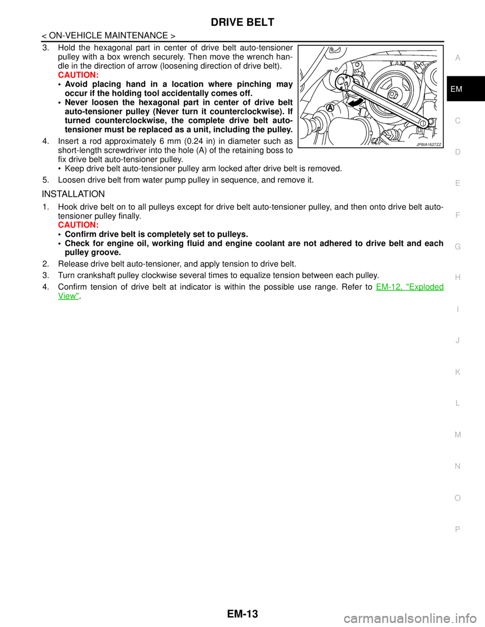
3. Hold the hexagonal part in center of drive belt auto-tensioner
pulley with a box wrench securely. Then move the wrench han-
dle in the direction of arrow (loosening direction of drive belt).
CAUTION:
Avoid placing hand in a location where pinching may
occur if the holding tool accidentally comes off.
Never loosen the hexagonal part in center of drive belt
auto-tensioner pulley (Never turn it counterclockwise). If
turned counterclockwise, the complete drive belt auto-
tensioner must be replaced as a unit, including the pulley.
4. Insert a rod approximately 6 mm (0.24 in) in diameter such as
short-length screwdriver into the hole (A) of the retaining boss to
fix drive belt auto-tensioner pulley.
Keep drive belt auto-tensioner pulley arm locked after drive belt is removed.
5. Loosen drive belt from water pump pulley in sequence, and remove it.
INSTALLATION
1. Hook drive belt on to all pulleys except for drive belt auto-tensioner pulley, and then onto drive belt auto-
tensioner pulley finally.
CAUTION:
Confirm drive belt is completely set to pulleys.
Check for engine oil, working fluid and engine coolant are not adhered to drive belt and each
pulley groove.
2. Release drive belt auto-tensioner, and apply tension to drive belt.
3. Turn crankshaft pulley clockwise several times to equalize tension between each pulley.
4. Confirm tension of drive belt at indicator is within the possible use range. Refer to EM-12, "
Exploded
View".
JPBIA1627ZZ
Page 1892 of 5121

CAMSHAFT VALVE CLEARANCE
EM-17
< ON-VEHICLE MAINTENANCE >
C
D
E
F
G
H
I
J
K
L
MA
EM
N
P O
CAMSHAFT VALVE CLEARANCE
Inspection and AdjustmentINFOID:0000000003802244
INSPECTION
Perform inspection as follows after removal, installation or replacement of camshaft or valve-related parts, or if
there is unusual engine conditions regarding valve clearance.
In cases of removing/installing or replacing camshaft and valve-
related parts, or of unusual engine conditions due to changes in
valve clearance (found malfunctions during stating, idling or causing
noise), perform inspection as follows:
1. Remove rocker covers (bank 1 and bank 2). Refer to EM-49, "
Exploded View".
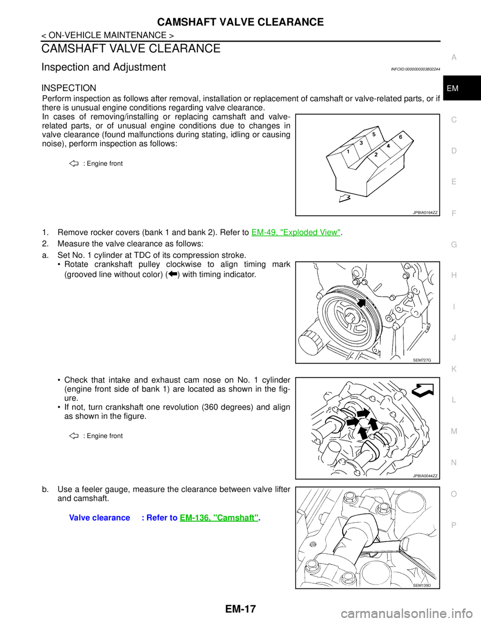
2. Measure the valve clearance as follows:
a. Set No. 1 cylinder at TDC of its compression stroke.
Rotate crankshaft pulley clockwise to align timing mark
(grooved line without color) ( ) with timing indicator.
Check that intake and exhaust cam nose on No. 1 cylinder
(engine front side of bank 1) are located as shown in the fig-
ure.
If not, turn crankshaft one revolution (360 degrees) and align
as shown in the figure.
b. Use a feeler gauge, measure the clearance between valve lifter
and camshaft.
: Engine front
JPBIA0164ZZ
SEM727G
: Engine front
JPBIA0044ZZ
Valve clearance : Refer to EM-136, "Camshaft".
SEM139D
Page 1928 of 5121

TIMING CHAIN
EM-53
< ON-VEHICLE REPAIR >
C
D
E
F
G
H
I
J
K
L
MA
EM
N
P O
Removal and InstallationINFOID:0000000003802270
REMOVAL
1. Drain engine oil. Refer to LU-8, "Draining".
2. Drain engine coolant from inside engine. Refer to EM-76, "
Setting".
3. Remove intake manifold collector. Refer to EM-28, "
Exploded View".
4. Remove rocker covers (bank 1 and bank 2). Refer to EM-49, "
Exploded View".
5. Remove oil pans (lower and upper) and oil strainer. Refer to EM-38, "
Exploded View".
6. Remove drive belt, idler pulleys and bracket. Refer to EM-12, "
Removal and Installation" and EM-25,
"Exploded View".
7. Separate engine harness removing their brackets from front timing chain case.
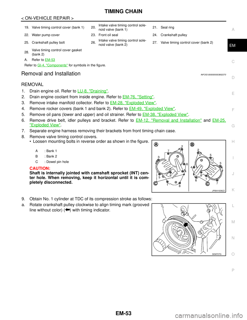
8. Remove valve timing control covers.
Loosen mounting bolts in reverse order as shown in the figure.
CAUTION:
Shaft is internally jointed with camshaft sprocket (INT) cen-
ter hole. When removing, keep it horizontal until it is com-
pletely disconnected.
9. Obtain No. 1 cylinder at TDC of its compression stroke as follows:
a. Rotate crankshaft pulley clockwise to align timing mark (grooved
line without color) ( ) with timing indicator.
19. Valve timing control cover (bank 1) 20.Intake valve timing control sole-
noid valve (bank 1)21. Seal ring
22. Water pump cover 23. Front oil seal 24. Crankshaft pulley
25. Crankshaft pulley bolt 26.Intake valve timing control sole-
noid valve (bank 2)27. Valve timing control cover (bank 2)
28.Valve timing control cover gasket
(bank 2)
A. Refer to EM-53
Refer to GI-4, "Components" for symbols in the figure.
A: Bank 1
B: Bank 2
C : Dowel pin hole
JPBIA1639ZZ
SEM727G
Page 2203 of 5121
![NISSAN TEANA 2008 Service Manual EXL-174
< ON-VEHICLE MAINTENANCE >[XENON TYPE]
HEADLAMP AIMING ADJUSTMENT
Aiming Adjustment Procedure (Low Beam)
INFOID:0000000003774533
1. Place the screen.
NOTE:
Stop the vehicle at the perpendic NISSAN TEANA 2008 Service Manual EXL-174
< ON-VEHICLE MAINTENANCE >[XENON TYPE]
HEADLAMP AIMING ADJUSTMENT
Aiming Adjustment Procedure (Low Beam)
INFOID:0000000003774533
1. Place the screen.
NOTE:
Stop the vehicle at the perpendic](/manual-img/5/57391/w960_57391-2202.png)
EXL-174
< ON-VEHICLE MAINTENANCE >[XENON TYPE]
HEADLAMP AIMING ADJUSTMENT
Aiming Adjustment Procedure (Low Beam)
INFOID:0000000003774533
1. Place the screen.
NOTE:
Stop the vehicle at the perpendicular angle to the wall.
Set the screen so that it is perpendicular to a level load surface.
2. Face the vehicle squarely toward the screen and make the distance between the headlamp center and
the screen 10 m (32.8 ft).
3. Start the engine and illuminate the headlamp (LO).
NOTE:
Block light from the headlamp that is not being adjusted with a thick fabric or another object, so that it
does not reach the adjustment screen.
CAUTION:
Do not cover lens surface with tape, etc. because it is made from plastic.
4. Use the aiming adjustment screw to adjust the elbow point projected by the low beams on the screen, so
that it is within the aiming adjustment area.
A. Headlamp (LO) RH
(UP/DOWN) adjustment screwB. Headlamp (HI) RH
(UP/DOWN) adjustment screwC. Headlamp (LO) RH
(UP-OUTSIDE/DOWN-INSIDE)
adjustment screw
D. Headlamp (HI) RH
(UP-INSIDE/DOWN-OUTSIDE)
adjustment screwE. Headlamp (LO) LH
(UP/DOWN) adjustment screwF. Headlamp (HI) LH
(UP/DOWN) adjustment screw
G. H e a d l a m p ( L O ) L H
(UP-OUTSIDE/DOWN-INSIDE)
adjustment screwH. Headlamp (HI) LH
(UP-INSIDE/DOWN-OUTSIDE)
adjustment screw
: Vehicle center
Adjustment screw Screw driver rotation Facing direction
AHeadlamp (LO) RH
(UP/DOWN)Clockwise UP
Counterclockwise DOWN
BHeadlamp (HI) RH
(UP/DOWN)Clockwise UP
Counterclockwise DOWN
CHeadlamp (LO) RH
(UP-OUTSIDE/DOWN-INSIDE)Clockwise DOWN-INSIDE
Counterclockwise UP-OUTSIDE
DHeadlamp (HI) RH
(UP-INSIDE/DOWN-OUTSIDE)Clockwise DOWN-OUTSIDE
Counterclockwise UP-INSIDE
EHeadlamp (LO) LH
(UP/DOWN)Clockwise UP
Counterclockwise DOWN
FHeadlamp (HI) LH
(UP/DOWN)Clockwise UP
Counterclockwise DOWN
GHeadlamp (LO) LH
(UP-OUTSIDE/DOWN-INSIDE)Clockwise DOWN-INSIDE
Counterclockwise UP-OUTSIDE
HHeadlamp (HI) LH
(UP-INSIDE/DOWN-OUTSIDE)Clockwise DOWN-OUTSIDE
Counterclockwise UP-INSIDE