2008 NISSAN TEANA set clock
[x] Cancel search: set clockPage 2366 of 5121
![NISSAN TEANA 2008 Service Manual HEADLAMP AIMING ADJUSTMENT
EXL-337
< ON-VEHICLE MAINTENANCE >[HALOGEN TYPE]
C
D
E
F
G
H
I
J
K
MA
B
EXL
N
O
P
Aiming Adjustment Procedure (Low Beam)INFOID:0000000003829236
1. Place the screen.
NOTE:
NISSAN TEANA 2008 Service Manual HEADLAMP AIMING ADJUSTMENT
EXL-337
< ON-VEHICLE MAINTENANCE >[HALOGEN TYPE]
C
D
E
F
G
H
I
J
K
MA
B
EXL
N
O
P
Aiming Adjustment Procedure (Low Beam)INFOID:0000000003829236
1. Place the screen.
NOTE:
](/manual-img/5/57391/w960_57391-2365.png)
HEADLAMP AIMING ADJUSTMENT
EXL-337
< ON-VEHICLE MAINTENANCE >[HALOGEN TYPE]
C
D
E
F
G
H
I
J
K
MA
B
EXL
N
O
P
Aiming Adjustment Procedure (Low Beam)INFOID:0000000003829236
1. Place the screen.
NOTE:
Stop the vehicle at the perpendicular angle to the wall.
Set the screen so that it is perpendicular to a level load surface.
2. Face the vehicle squarely toward the screen and make the distance between the headlamp center and
the screen 10 m (32.8 ft).
3. Start the engine and illuminate the headlamp (LO).
NOTE:
Block light from the headlamp that is not being adjusted with a thick fabric or another object, so that it
does not reach the adjustment screen.
CAUTION:
Do not cover lens surface with tape, etc. because it is made from plastic.
4. Use the aiming adjustment screw to adjust the elbow point projected by the low beams on the screen, so
that it is within the aiming adjustment area.
A. Headlamp (LO) RH
(UP/DOWN) adjustment screwB. Headlamp (HI) RH
(UP/DOWN) adjustment screwC. Headlamp (LO) RH
(UP-OUTSIDE/DOWN-INSIDE)
adjustment screw
D. Headlamp (HI) RH
(UP-INSIDE/DOWN-OUTSIDE)
adjustment screwE. Headlamp (LO) LH
(UP/DOWN) adjustment screwF. Headlamp (HI) LH
(UP/DOWN) adjustment screw
G. H e a d l a m p ( L O ) L H
(UP-OUTSIDE/DOWN-INSIDE)
adjustment screwH. Headlamp (HI) LH
(UP-INSIDE/DOWN-OUTSIDE)
adjustment screw
: Vehicle center
Adjustment screw Screw driver rotation Facing direction
AHeadlamp (LO) RH
(UP/DOWN)Clockwise UP
Counterclockwise DOWN
BHeadlamp (HI) RH
(UP/DOWN)Clockwise UP
Counterclockwise DOWN
CHeadlamp (LO) RH
(UP-OUTSIDE/DOWN-INSIDE)Clockwise DOWN-INSIDE
Counterclockwise UP-OUTSIDE
DHeadlamp (HI) RH
(UP-INSIDE/DOWN-OUTSIDE)Clockwise DOWN-OUTSIDE
Counterclockwise UP-INSIDE
EHeadlamp (LO) LH
(UP/DOWN)Clockwise UP
Counterclockwise DOWN
FHeadlamp (HI) LH
(UP/DOWN)Clockwise UP
Counterclockwise DOWN
GHeadlamp (LO) LH
(UP-OUTSIDE/DOWN-INSIDE)Clockwise DOWN-INSIDE
Counterclockwise UP-OUTSIDE
HHeadlamp (HI) LH
(UP-INSIDE/DOWN-OUTSIDE)Clockwise DOWN-OUTSIDE
Counterclockwise UP-INSIDE
Page 2586 of 5121

PRECAUTIONS
HA-17
< PRECAUTION >
C
D
E
F
G
H
J
K
L
MA
B
HA
N
O
P
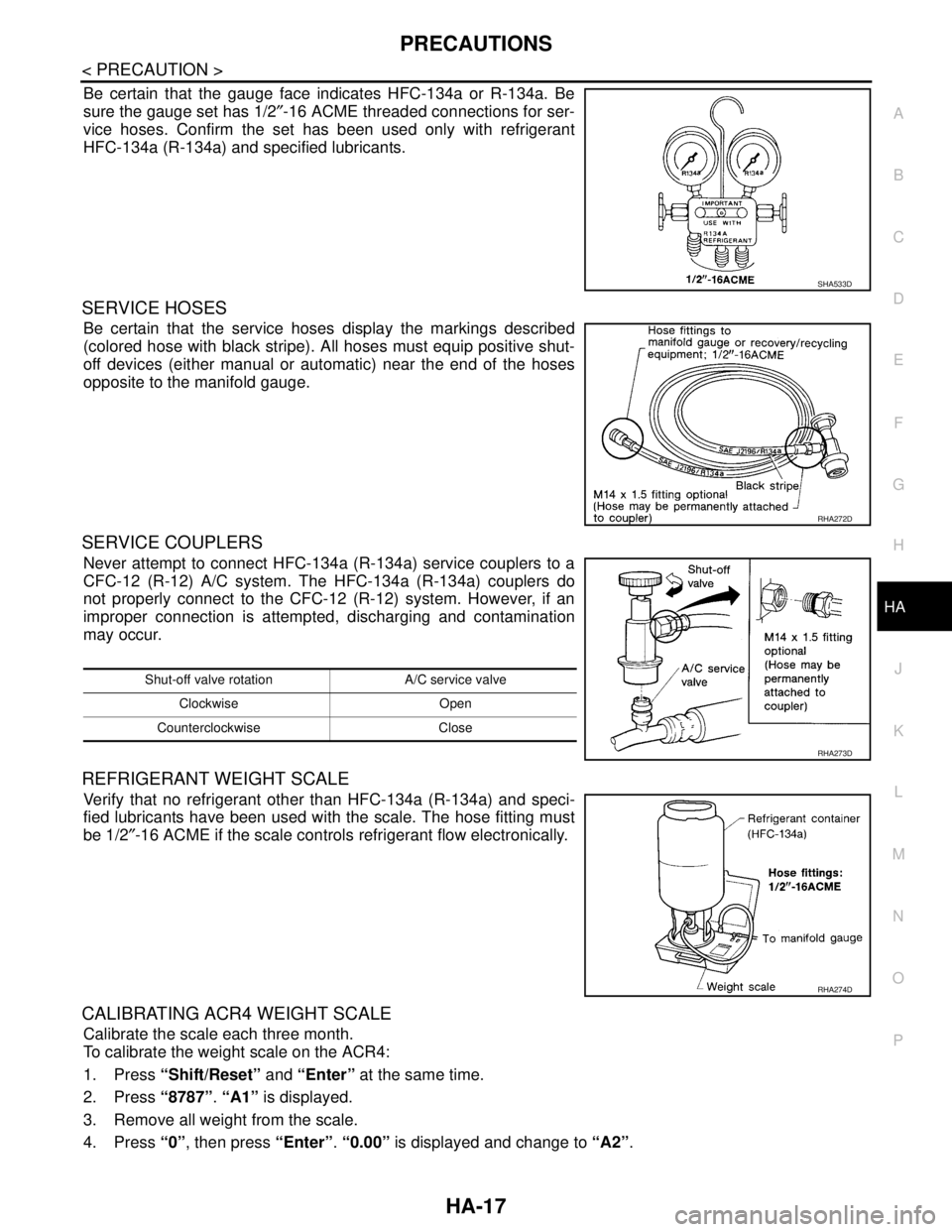
Be certain that the gauge face indicates HFC-134a or R-134a. Be
sure the gauge set has 1/2″-16 ACME threaded connections for ser-
vice hoses. Confirm the set has been used only with refrigerant
HFC-134a (R-134a) and specified lubricants.
SERVICE HOSES
Be certain that the service hoses display the markings described
(colored hose with black stripe). All hoses must equip positive shut-
off devices (either manual or automatic) near the end of the hoses
opposite to the manifold gauge.
SERVICE COUPLERS
Never attempt to connect HFC-134a (R-134a) service couplers to a
CFC-12 (R-12) A/C system. The HFC-134a (R-134a) couplers do
not properly connect to the CFC-12 (R-12) system. However, if an
improper connection is attempted, discharging and contamination
may occur.
REFRIGERANT WEIGHT SCALE
Verify that no refrigerant other than HFC-134a (R-134a) and speci-
fied lubricants have been used with the scale. The hose fitting must
be 1/2″-16 ACME if the scale controls refrigerant flow electronically.
CALIBRATING ACR4 WEIGHT SCALE
Calibrate the scale each three month.
To calibrate the weight scale on the ACR4:
1. Press “Shift/Reset” and “Enter” at the same time.
2. Press “8787”. “A1” is displayed.
3. Remove all weight from the scale.
4. Press “0”, then press “Enter”. “0.00” is displayed and change to “A2”.
SHA533D
RHA272D
Shut-off valve rotation A/C service valve
Clockwise Open
Counterclockwise Close
RHA273D
RHA274D
Page 2742 of 5121
![NISSAN TEANA 2008 Service Manual HAC-114
< BASIC INSPECTION >[WITH 7 INCH DISPLAY]
INSPECTION AND ADJUSTMENT
2. Ion indicator is shown on the display.
3. Press OFF switch.
4. Ion indicator is turned OFF.
Is the inspection result norm NISSAN TEANA 2008 Service Manual HAC-114
< BASIC INSPECTION >[WITH 7 INCH DISPLAY]
INSPECTION AND ADJUSTMENT
2. Ion indicator is shown on the display.
3. Press OFF switch.
4. Ion indicator is turned OFF.
Is the inspection result norm](/manual-img/5/57391/w960_57391-2741.png)
HAC-114
< BASIC INSPECTION >[WITH 7 INCH DISPLAY]
INSPECTION AND ADJUSTMENT
2. Ion indicator is shown on the display.
3. Press OFF switch.
4. Ion indicator is turned OFF.
Is the inspection result normal?
YES >> GO TO 11.
NO >> Refer to HAC-227, "
WITH INTELLIGENT AIR CONDITIONER SYSTEM : Inspection procedure".
11 .CHECK ION CONTROL MODE
1. Turn ignition switch OFF and restart the engine.
2. Turn fan control dial clockwise.
3. Ion indicator (blue) is turned ON.
4. Ion indicator (blue) changes to ion indicator (green) after approximately 15 minutes.
5. Ion indicator (green) changes to ion indicator (blue) after approximately 15 minutes.
6. Press CLEAN switch.
7. Ion indicator (blue) changes to ion indicator (green) after approximately 30 minutes.
8. Ion indicator (green) changes to ion indicator (blue) after approximately 15 minutes.
Is the inspection result normal?
YES >> INSPECTION END
NO >> Replace unified meter and A/C amp.
WITH INTELLIGENT AIR CONDITIONER SYSTEM : Temperature Setting Trimmer
INFOID:0000000003888718
DESCRIPTION
If the temperature felt by the customer is different than the air flow temperature controlled by the temperature
setting, the A/C auto amp. control temperature can be adjusted to compensate for the temperature setting.
HOW TO SET
Using CONSULT-III, perform “TEMP SET CORRECT” on “WORK SUPPORT” of HVAC.
NOTE:
When the temperature setting is set to 25.0°C (77°F) and −3.0°C (−6°F), the temperature controlled by A/C
auto amp. is 25.0°C (77°F) −3.0°C (6°F) = 22.0°C (71°F) and the temperature becomes lower than the tem-
perature setting.
When the battery cable is disconnected from the negative terminal or when the battery voltage becomes 10
V or less, trimmer operation is canceled. Temperature set becomes that of initial condition.
WITH INTELLIGENT AIR CONDITIONER SYSTEM : Foot Position Setting Trimmer
INFOID:0000000003888719
DESCRIPTION
Work support items Display (°F) Display (°C)
TEMP SET CORRECT63.0
52.5
42.0
31.5
21.0
10.5
0 (initial status) 0 (initial status)
−1−0.5
−2−1.0
−3−1.5
−4−2.0
−5−2.5
−6−3.0
Page 3212 of 5121

MA-24
< ON-VEHICLE MAINTENANCE >
CHASSIS MAINTENANCE
HEADLAMP AIMING ADJUSTMENT (XENON TYPE) : Aiming Adjustment Procedure
(Low Beam)
INFOID:0000000003862421
1. Place the screen.
NOTE:
Stop the vehicle at the perpendicular angle to the wall.
Set the screen so that it is perpendicular to a level load surface.
2. Face the vehicle squarely toward the screen and make the distance between the headlamp center and
the screen 10 m (32.8 ft).
3. Start the engine and illuminate the headlamp (LO).
NOTE:
Block light from the headlamp that is not being adjusted with a thick fabric or another object, so that it
does not reach the adjustment screen.
CAUTION:
Do not cover lens surface with tape, etc. because it is made from plastic.
4. Use the aiming adjustment screw to adjust the elbow point projected by the low beams on the screen, so
that it is within the aiming adjustment area.
A. Headlamp (LO) RH
(UP/DOWN) adjustment screwB. Headlamp (HI) RH
(UP/DOWN) adjustment screwC. Headlamp (LO) RH
(UP-OUTSIDE/DOWN-INSIDE)
adjustment screw
D. Headlamp (HI) RH
(UP-INSIDE/DOWN-OUTSIDE)
adjustment screwE. Headlamp (LO) LH
(UP/DOWN) adjustment screwF. Headlamp (HI) LH
(UP/DOWN) adjustment screw
G. H e a d l a m p ( L O ) L H
(UP-OUTSIDE/DOWN-INSIDE)
adjustment screwH. Headlamp (HI) LH
(UP-INSIDE/DOWN-OUTSIDE)
adjustment screw
: Vehicle center
Adjustment screw Screw driver rotation Facing direction
AHeadlamp (LO) RH
(UP/DOWN)Clockwise UP
Counterclockwise DOWN
BHeadlamp (HI) RH
(UP/DOWN)Clockwise UP
Counterclockwise DOWN
CHeadlamp (LO) RH
(UP-OUTSIDE/DOWN-INSIDE)Clockwise DOWN-INSIDE
Counterclockwise UP-OUTSIDE
DHeadlamp (HI) RH
(UP-INSIDE/DOWN-OUTSIDE)Clockwise DOWN-OUTSIDE
Counterclockwise UP-INSIDE
EHeadlamp (LO) LH
(UP/DOWN)Clockwise UP
Counterclockwise DOWN
FHeadlamp (HI) LH
(UP/DOWN)Clockwise UP
Counterclockwise DOWN
GHeadlamp (LO) LH
(UP-OUTSIDE/DOWN-INSIDE)Clockwise DOWN-INSIDE
Counterclockwise UP-OUTSIDE
HHeadlamp (HI) LH
(UP-INSIDE/DOWN-OUTSIDE)Clockwise DOWN-OUTSIDE
Counterclockwise UP-INSIDE
Page 3217 of 5121

CHASSIS MAINTENANCE
MA-29
< ON-VEHICLE MAINTENANCE >
C
D
E
F
G
H
I
J
K
L
MB
MAN
OA
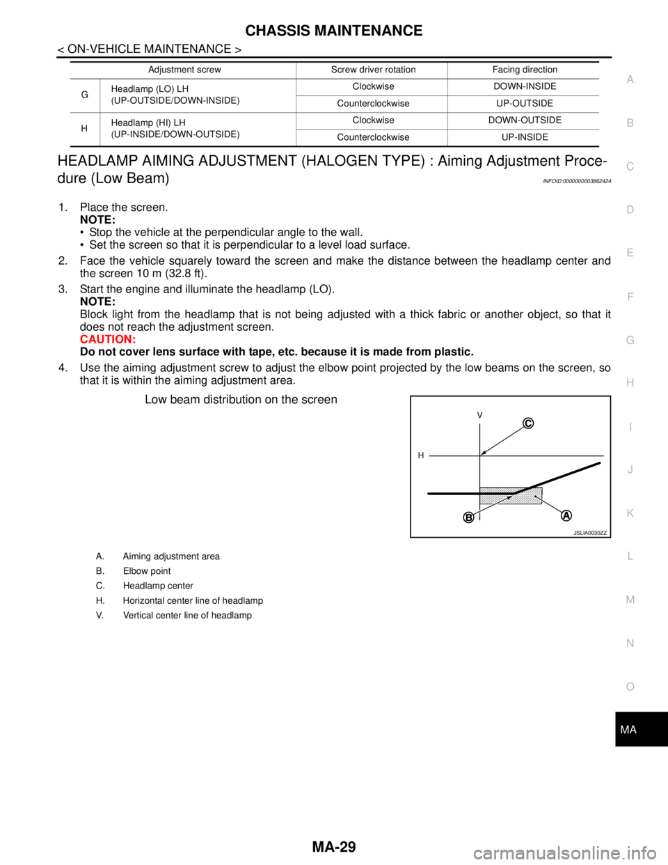
HEADLAMP AIMING ADJUSTMENT (HALOGEN TYPE) : Aiming Adjustment Proce-
dure (Low Beam)
INFOID:0000000003862424
1. Place the screen.
NOTE:
Stop the vehicle at the perpendicular angle to the wall.
Set the screen so that it is perpendicular to a level load surface.
2. Face the vehicle squarely toward the screen and make the distance between the headlamp center and
the screen 10 m (32.8 ft).
3. Start the engine and illuminate the headlamp (LO).
NOTE:
Block light from the headlamp that is not being adjusted with a thick fabric or another object, so that it
does not reach the adjustment screen.
CAUTION:
Do not cover lens surface with tape, etc. because it is made from plastic.
4. Use the aiming adjustment screw to adjust the elbow point projected by the low beams on the screen, so
that it is within the aiming adjustment area.
Low beam distribution on the screen
GHeadlamp (LO) LH
(UP-OUTSIDE/DOWN-INSIDE)Clockwise DOWN-INSIDE
Counterclockwise UP-OUTSIDE
HHeadlamp (HI) LH
(UP-INSIDE/DOWN-OUTSIDE)Clockwise DOWN-OUTSIDE
Counterclockwise UP-INSIDE Adjustment screw Screw driver rotation Facing direction
JSLIA0030ZZ
A. Aiming adjustment area
B. Elbow point
C. Headlamp center
H. Horizontal center line of headlamp
V. Vertical center line of headlamp
Page 4224 of 5121

SR-10
< ON-VEHICLE REPAIR >
SPIRAL CABLE
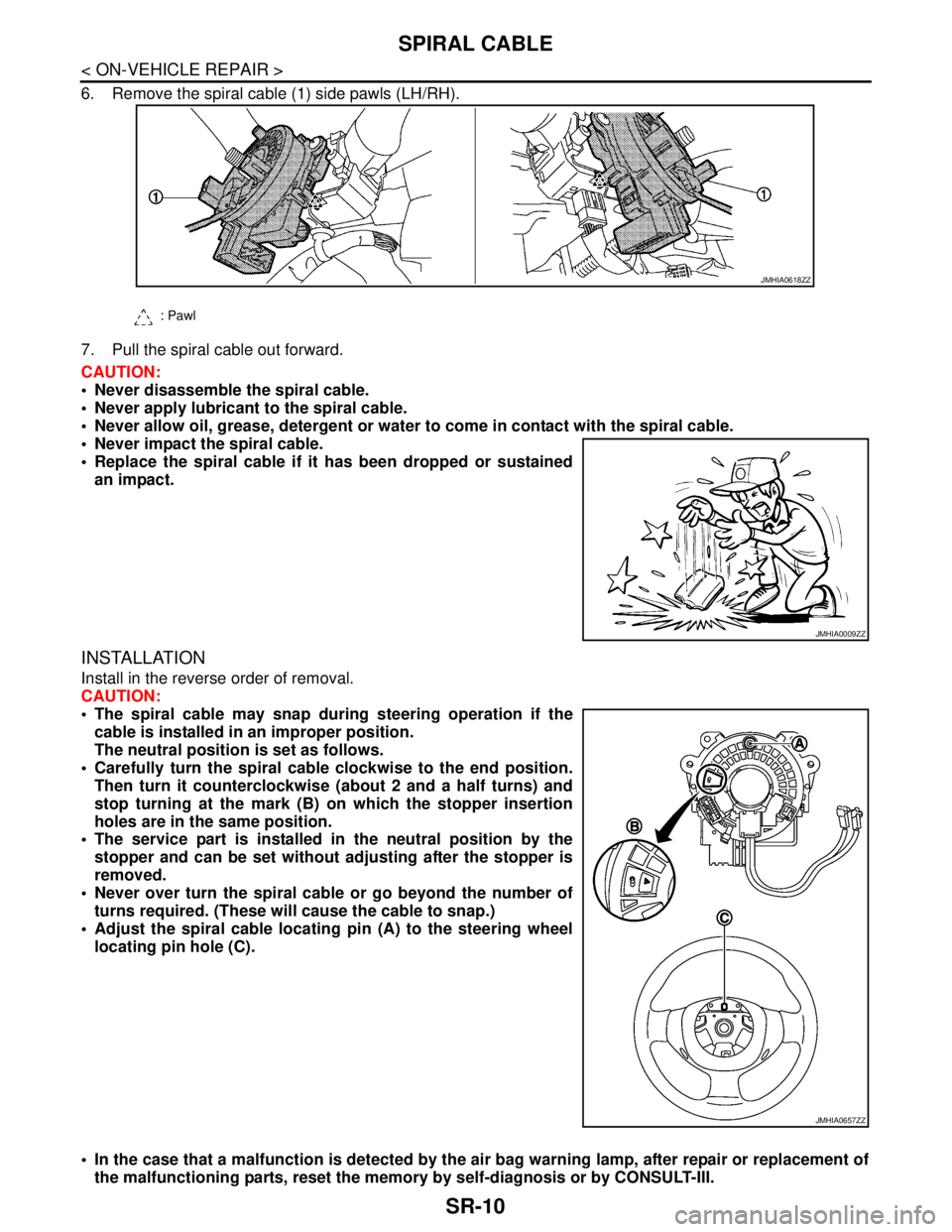
6. Remove the spiral cable (1) side pawls (LH/RH).
7. Pull the spiral cable out forward.
CAUTION:
Never disassemble the spiral cable.
Never apply lubricant to the spiral cable.
Never allow oil, grease, detergent or water to come in contact with the spiral cable.
Never impact the spiral cable.
Replace the spiral cable if it has been dropped or sustained
an impact.
INSTALLATION
Install in the reverse order of removal.
CAUTION:
The spiral cable may snap during steering operation if the
cable is installed in an improper position.
The neutral position is set as follows.
Carefully turn the spiral cable clockwise to the end position.
Then turn it counterclockwise (about 2 and a half turns) and
stop turning at the mark (B) on which the stopper insertion
holes are in the same position.
The service part is installed in the neutral position by the
stopper and can be set without adjusting after the stopper is
removed.
Never over turn the spiral cable or go beyond the number of
turns required. (These will cause the cable to snap.)
Adjust the spiral cable locating pin (A) to the steering wheel
locating pin hole (C).
In the case that a malfunction is detected by the air bag warning lamp, after repair or replacement of
the malfunctioning parts, reset the memory by self-diagnosis or by CONSULT-III.
: Pawl
JMHIA0618ZZ
JMHIA0009ZZ
JMHIA0657ZZ
Page 4643 of 5121
![NISSAN TEANA 2008 Service Manual TM-170
< REMOVAL AND INSTALLATION >[CVT: RE0F09B]
TRANSAXLE ASSEMBLY
When using the drive plate location guide (commercial service tool:
31197CA000) (A), set it to the stud bolts which is used to in NISSAN TEANA 2008 Service Manual TM-170
< REMOVAL AND INSTALLATION >[CVT: RE0F09B]
TRANSAXLE ASSEMBLY
When using the drive plate location guide (commercial service tool:
31197CA000) (A), set it to the stud bolts which is used to in](/manual-img/5/57391/w960_57391-4642.png)
TM-170
< REMOVAL AND INSTALLATION >[CVT: RE0F09B]
TRANSAXLE ASSEMBLY
When using the drive plate location guide (commercial service tool:
31197CA000) (A), set it to the stud bolts which is used to install it
to the torque converter.
When not using drive plate location guide, rotate torque converter
so that the stud bolt (B) for mounting the drive plate location guide
of torque converter aligns with the mounting position of service
hole.
Rotate crankshaft so that the hole (A) for inserting drive plate loca-
tion guide of drive plate aligns with the service hole (B).
NOTE:
When not using drive plate location guide, insert stud bolt of torque
converter into the hole (C) of drive plate, aligning the drive plate
hole position and torque converter.
CAUTION:
Be careful not to strike the drive plate when installing the
torque converter stud bolt.
Align the position of tightening nuts ( ) for drive plate with those
of the torque converter, and temporarily tighten the nuts. Then,
tighten the bolts to the specified torque.
CAUTION:
When turning crankshaft, turn it clockwise as viewed from the
front of the engine.
When tightening the nuts for the torque converter after fixing
the crankshaft pulley bolts, confirm the tightening torque of
the crankshaft pulley mounting bolts. Refer to EM-79,
"Exploded View".
Rotate crankshaft several turns and check that transaxle rotates freely without binding after con-
verter is installed to drive plate.
Never reuse O-ring.
Apply petroleum jelly to O-ring.
InspectionINFOID:0000000003849110
INSPECTION BEFORE INSTALLATION
After inserting a torque converter to transaxle assembly, check that
distance (A) is within the reference value limit.
INSPECTION AFTER INSTALLATION
Check the following items.
JPDIA0607ZZ
JPDIA0603ZZ
: 51 N·m (5.2 kg-m,38 ft-lb)
SCIA1861E
B: Scale
C : Straightedge
Distance A : Refer to TM-175, "Torque Converter".
JPDIA0620ZZ
Page 4823 of 5121
![NISSAN TEANA 2008 Service Manual VTL-12
< PRECAUTION >[WITHOUT 7 INCH DISPLAY]
PRECAUTIONS
Be certain that the gauge face indicates HFC-134a or R-134a. Be
sure the gauge set has 1/2″-16 ACME threaded connections for ser-
vice hoses NISSAN TEANA 2008 Service Manual VTL-12
< PRECAUTION >[WITHOUT 7 INCH DISPLAY]
PRECAUTIONS
Be certain that the gauge face indicates HFC-134a or R-134a. Be
sure the gauge set has 1/2″-16 ACME threaded connections for ser-
vice hoses](/manual-img/5/57391/w960_57391-4822.png)
VTL-12
< PRECAUTION >[WITHOUT 7 INCH DISPLAY]
PRECAUTIONS
Be certain that the gauge face indicates HFC-134a or R-134a. Be
sure the gauge set has 1/2″-16 ACME threaded connections for ser-
vice hoses. Confirm the set has been used only with refrigerant
HFC-134a (R-134a) and specified lubricants.
SERVICE HOSES
Be certain that the service hoses display the markings described
(colored hose with black stripe). All hoses must equip positive shut-
off devices (either manual or automatic) near the end of the hoses
opposite to the manifold gauge.
SERVICE COUPLERS
Never attempt to connect HFC-134a (R-134a) service couplers to a
CFC-12 (R-12) A/C system. The HFC-134a (R-134a) couplers do
not properly connect to the CFC-12 (R-12) system. However, if an
improper connection is attempted, discharging and contamination
may occur.
REFRIGERANT WEIGHT SCALE
Verify that no refrigerant other than HFC-134a (R-134a) and speci-
fied lubricants have been used with the scale. The hose fitting must
be 1/2″-16 ACME if the scale controls refrigerant flow electronically.
CALIBRATING ACR4 WEIGHT SCALE
Calibrate the scale each three month.
To calibrate the weight scale on the ACR4:
1. Press “Shift/Reset” and “Enter” at the same time.
2. Press “8787”. “A1” is displayed.
3. Remove all weight from the scale.
4. Press “0”, then press “Enter”. “0.00” is displayed and change to “A2”.
SHA533D
RHA272D
Shut-off valve rotation A/C service valve
Clockwise Open
Counterclockwise Close
RHA273D
RHA274D