2008 NISSAN TEANA check transmission fluid
[x] Cancel search: check transmission fluidPage 1585 of 5121
![NISSAN TEANA 2008 Service Manual EC-124
< COMPONENT DIAGNOSIS >[VQ25DE, VQ35DE]
TROUBLE DIAGNOSIS - SPECIFICATION VALUE
COMPONENT DIAGNOSIS
TROUBLE DIAGNOSIS - SPECIFICATION VALUE
DescriptionINFOID:0000000003856505
The specification NISSAN TEANA 2008 Service Manual EC-124
< COMPONENT DIAGNOSIS >[VQ25DE, VQ35DE]
TROUBLE DIAGNOSIS - SPECIFICATION VALUE
COMPONENT DIAGNOSIS
TROUBLE DIAGNOSIS - SPECIFICATION VALUE
DescriptionINFOID:0000000003856505
The specification](/manual-img/5/57391/w960_57391-1584.png)
EC-124
< COMPONENT DIAGNOSIS >[VQ25DE, VQ35DE]
TROUBLE DIAGNOSIS - SPECIFICATION VALUE
COMPONENT DIAGNOSIS
TROUBLE DIAGNOSIS - SPECIFICATION VALUE
DescriptionINFOID:0000000003856505
The specification (SP) value indicates the tolerance of the value that is displayed in “SPEC” of “DATA MONI-
TOR” mode of CONSULT-III during normal operation of the Engine Control System. When the value in “SPEC”
in “DATA MONITOR” mode is NOT within the SP value, the Engine Control System may have one or more
malfunctions.
The SP value is used to detect malfunctions that may affect the Engine Control System, but will not illuminate
the MI.
The SP value will be displayed for the following three items:
B/FUEL SCHDL (The fuel injection pulse width programmed into ECM prior to any learned on board correc-
tion)
A/F ALPHA-B1/B2 (The mean value of air-fuel ratio feedback correction factor per cycle)
MAS A/F SE-B1 (The signal voltage of the mass air flow sensor)
Component Function CheckINFOID:0000000003856506
1.START
Check that all of the following conditions are satisfied.
Vehicle driven distance: More than 5,000 km (3,107 miles)
Barometric pressure: 98.3 - 104.3 kPa (0.983 - 1.043 bar, 1.003 - 1.064 kg/cm
2, 14.25 - 15.12 psi)
Atmospheric temperature: 20 - 30°C (68 - 86°F)
Engine coolant temperature: 75 - 95°C (167 - 203°F)
Transmission: Warmed-up
- After the engine is warmed up to normal operating temperature, drive vehicle until “FLUID TEMP SE” (CVT
fluid temperature sensor signal) indicates more than 60°C (140°F).
Electrical load: Not applied
- Rear window defogger switch, air conditioner switch, lighting switch are OFF. Steering wheel is straight
ahead.
Engine speed: Idle
>> GO TO 2.
2.PERFORM “SPEC” OF “DATA MONITOR” MODE
With CONSULT-III
NOTE:
Perform “SPEC” in “DATA MONITOR” mode in maximum scale display.
1. Perform “EC-11, "
BASIC INSPECTION : Special Repair Requirement".
2. Select “B/FUEL SCHDL”, “A/F ALPHA-B1”, “A/F ALPHA-B2” and “MAS A/F SE-B1” in “SPEC” of “DATA
MONITOR” mode with CONSULT-III.
3. Check that monitor items are within the SP value.
Is the measurement value within the SP value?
YES >> INSPECTION END
NO >> Go to EC-125, "
Diagnosis Procedure".
Page 1941 of 5121

EM-66
< ON-VEHICLE REPAIR >
TIMING CHAIN
Use procedure below to check for fuel leakage.
- Turn ignition switch “ON” (with engine stopped). With fuel pressure applied to fuel piping, check for fuel leak-
age at connection points.
- Start engine. With engine speed increased, check again for fuel leakage at connection points.
Run engine to check for unusual noise and vibration.
NOTE:
If hydraulic pressure inside chain tensioner drops after removal/installation, slack in guide may generate a
pounding noise during and just after the engine start. However, this does not indicate an unusualness. Noise
will stop after hydraulic pressure rises.
Warm up engine thoroughly to check there is no leakage of fuel, or any oil/fluids including engine oil and
engine coolant.
Bleed air from lines and hoses of applicable lines, such as in cooling system.
After cooling down engine, again check oil/fluid levels including engine oil and engine coolant. Refill to the
specified level, if necessary.
Summary of the inspection items:
*: Transmission/transaxle/CVT fluid, power steering fluid, brake fluid, etc.Items Before starting engine Engine running After engine stopped
Engine coolant Level Leakage Level
Engine oil Level Leakage Level
Other oils and fluid* Level Leakage Level
Fuel Leakage Leakage Leakage
Page 1944 of 5121
ENGINE ASSEMBLY
EM-69
< REMOVAL AND INSTALLATION >
C
D
E
F
G
H
I
J
K
L
MA
EM
N
P O
10. Remove starter motor. Refer to STR-15, "VQ25DE : Exploded View" (VQ25DE) or STR-20, "VQ35DE :
Exploded View" (VQ35DE).
Vehicle Underbody
1. Remove front drive shafts (RH and LH). Refer to FAX-16, "Exploded View".
2. Remove exhaust front tube. Refer to EX-5, "
Exploded View".
3. Remove heat insulator.
4. Disconnect steering lower joint at power steering gear assembly side, and release steering lower shaft.
Refer to ST-16, "
Exploded View".
5. Disconnect front stabilizer connecting rod. Refer to FSU-14, "
Exploded View".
6. Remove strut assembly and steering knuckle fixing nuts and bolts. Refer to FSU-9, "
Exploded View" and
FA X - 8 , "
Exploded View".
7. Remove front wheel sensor (RH and LH) for ABS from steering knuckle. Refer to BRC-57, "
FRONT
WHEEL SENSOR : Exploded View".
8. Remove front brake caliper assembly with piping connected, and temporarily secure it to aside for vehicle
side. Refer to BR-34, "
BRAKE CALIPER ASSEMBLY : Exploded View".
9. Disconnect power steering piping at a point between vehicle and engine. Refer to ST-34, "
Exploded
View".
Install plug to avoid leakage of power steering fluid.
10. Remove rear plate cover from oil pan (upper). Then remove bolts fixing drive plate to torque converter.
Refer to EM-38, "
Exploded View" and TM-332, "Removal and Installation" (VQ25DE) or TM-168,
"Removal and Installation" (VQ35DE).
11. Remove transaxle joint bolts which pierce at oil pan (upper) lower rear side. Refer to EM-38, "
Exploded
View".
12. Remove crankshaft position sensor (POS). Refer to EM-38, "
Exploded View".
CAUTION:
Handle carefully to avoid dropping and shocks.
Never disassemble.
Never allow metal powder to adhere to magnetic part at sensor tip.
Never place sensors in a location where they are exposed to magnetism.
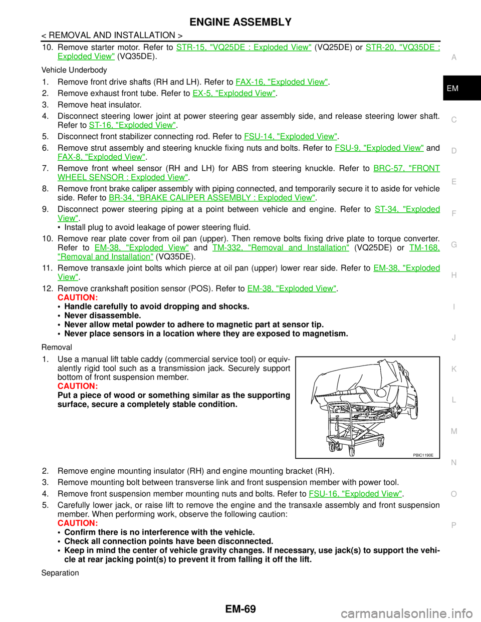
Removal
1. Use a manual lift table caddy (commercial service tool) or equiv-
alently rigid tool such as a transmission jack. Securely support
bottom of front suspension member.
CAUTION:
Put a piece of wood or something similar as the supporting
surface, secure a completely stable condition.
2. Remove engine mounting insulator (RH) and engine mounting bracket (RH).
3. Remove mounting bolt between transverse link and front suspension member with power tool.
4. Remove front suspension member mounting nuts and bolts. Refer to FSU-16, "
Exploded View".
5. Carefully lower jack, or raise lift to remove the engine and the transaxle assembly and front suspension
member. When performing work, observe the following caution:
CAUTION:
Confirm there is no interference with the vehicle.
Check all connection points have been disconnected.
Keep in mind the center of vehicle gravity changes. If necessary, use jack(s) to support the vehi-
cle at rear jacking point(s) to prevent it from falling it off the lift.
Separation
PBIC1190E
Page 1950 of 5121
ENGINE ASSEMBLY
EM-75
< REMOVAL AND INSTALLATION >
C
D
E
F
G
H
I
J
K
L
MA
EM
N
P O
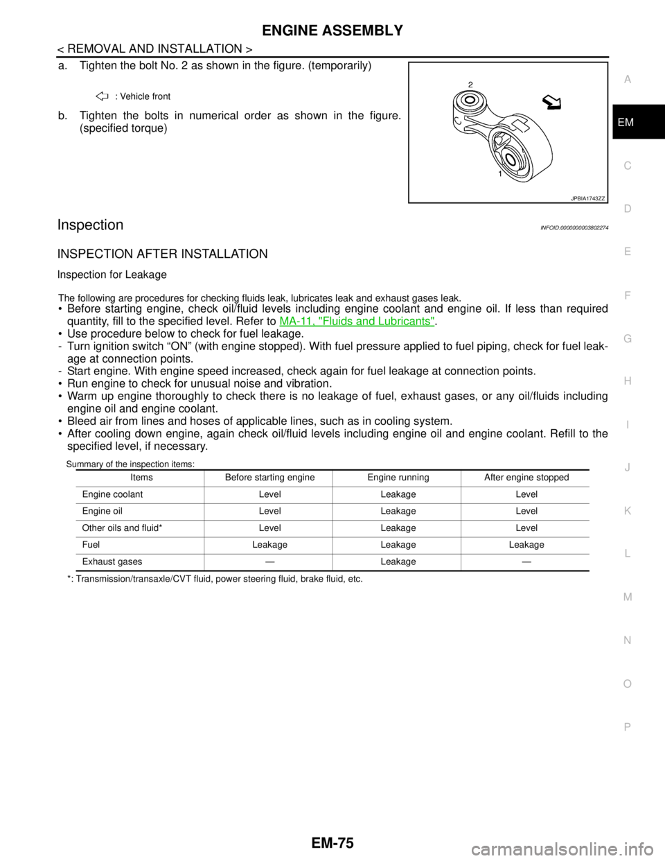
a. Tighten the bolt No. 2 as shown in the figure. (temporarily)
b. Tighten the bolts in numerical order as shown in the figure.
(specified torque)
InspectionINFOID:0000000003802274
INSPECTION AFTER INSTALLATION
Inspection for Leakage
The following are procedures for checking fluids leak, lubricates leak and exhaust gases leak.
Before starting engine, check oil/fluid levels including engine coolant and engine oil. If less than required
quantity, fill to the specified level. Refer to MA-11, "
Fluids and Lubricants".
Use procedure below to check for fuel leakage.
- Turn ignition switch “ON” (with engine stopped). With fuel pressure applied to fuel piping, check for fuel leak-
age at connection points.
- Start engine. With engine speed increased, check again for fuel leakage at connection points.
Run engine to check for unusual noise and vibration.
Warm up engine thoroughly to check there is no leakage of fuel, exhaust gases, or any oil/fluids including
engine oil and engine coolant.
Bleed air from lines and hoses of applicable lines, such as in cooling system.
After cooling down engine, again check oil/fluid levels including engine oil and engine coolant. Refill to the
specified level, if necessary.
Summary of the inspection items:
*: Transmission/transaxle/CVT fluid, power steering fluid, brake fluid, etc.: Vehicle front
JPBIA1743ZZ
Items Before starting engine Engine running After engine stopped
Engine coolant Level Leakage Level
Engine oil Level Leakage Level
Other oils and fluid* Level Leakage Level
Fuel Leakage Leakage Leakage
Exhaust gases — Leakage —
Page 1967 of 5121
EM-92
< DISASSEMBLY AND ASSEMBLY >
CAMSHAFT
b. Disconnect ignition coil and injector harness connectors. Refer to EM-49, "Exploded View" and EM-44,
"Exploded View".
3. Remove intake valve timing control solenoid valve. Refer to EM-79, "
Exploded View".
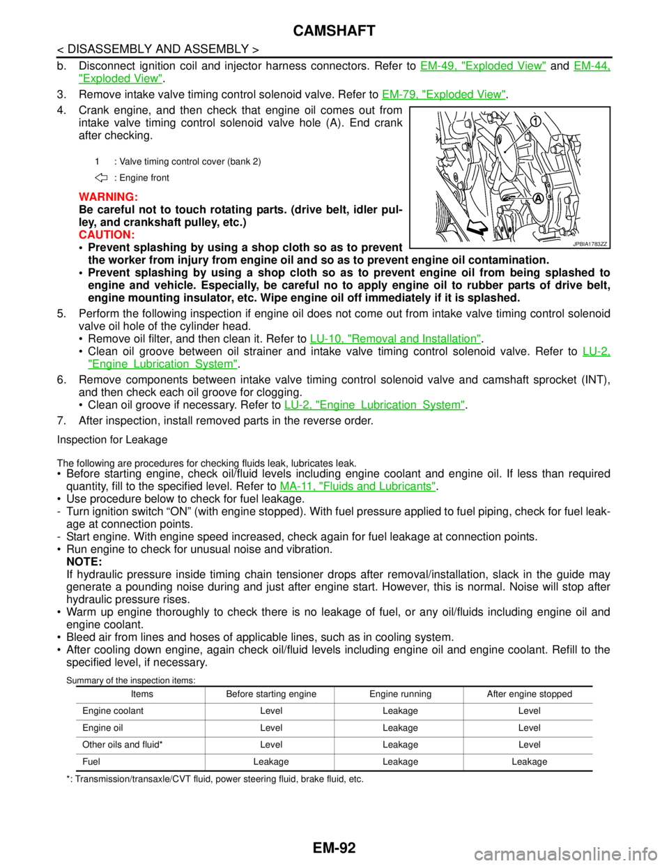
4. Crank engine, and then check that engine oil comes out from
intake valve timing control solenoid valve hole (A). End crank
after checking.
WARNING:
Be careful not to touch rotating parts. (drive belt, idler pul-
ley, and crankshaft pulley, etc.)
CAUTION:
Prevent splashing by using a shop cloth so as to prevent
the worker from injury from engine oil and so as to prevent engine oil contamination.
Prevent splashing by using a shop cloth so as to prevent engine oil from being splashed to
engine and vehicle. Especially, be careful no to apply engine oil to rubber parts of drive belt,
engine mounting insulator, etc. Wipe engine oil off immediately if it is splashed.
5. Perform the following inspection if engine oil does not come out from intake valve timing control solenoid
valve oil hole of the cylinder head.
Remove oil filter, and then clean it. Refer to LU-10, "
Removal and Installation".
Clean oil groove between oil strainer and intake valve timing control solenoid valve. Refer to LU-2,
"EngineLubricationSystem".
6. Remove components between intake valve timing control solenoid valve and camshaft sprocket (INT),
and then check each oil groove for clogging.
Clean oil groove if necessary. Refer to LU-2, "
EngineLubricationSystem".
7. After inspection, install removed parts in the reverse order.
Inspection for Leakage
The following are procedures for checking fluids leak, lubricates leak. Before starting engine, check oil/fluid levels including engine coolant and engine oil. If less than required
quantity, fill to the specified level. Refer to MA-11, "
Fluids and Lubricants".
Use procedure below to check for fuel leakage.
- Turn ignition switch “ON” (with engine stopped). With fuel pressure applied to fuel piping, check for fuel leak-
age at connection points.
- Start engine. With engine speed increased, check again for fuel leakage at connection points.
Run engine to check for unusual noise and vibration.
NOTE:
If hydraulic pressure inside timing chain tensioner drops after removal/installation, slack in the guide may
generate a pounding noise during and just after engine start. However, this is normal. Noise will stop after
hydraulic pressure rises.
Warm up engine thoroughly to check there is no leakage of fuel, or any oil/fluids including engine oil and
engine coolant.
Bleed air from lines and hoses of applicable lines, such as in cooling system.
After cooling down engine, again check oil/fluid levels including engine oil and engine coolant. Refill to the
specified level, if necessary.
Summary of the inspection items:
*: Transmission/transaxle/CVT fluid, power steering fluid, brake fluid, etc.1 : Valve timing control cover (bank 2)
: Engine front
JPBIA1783ZZ
Items Before starting engine Engine running After engine stopped
Engine coolant Level Leakage Level
Engine oil Level Leakage Level
Other oils and fluid* Level Leakage Level
Fuel Leakage Leakage Leakage
Page 1981 of 5121
EM-106
< DISASSEMBLY AND ASSEMBLY >
CYLINDER HEAD
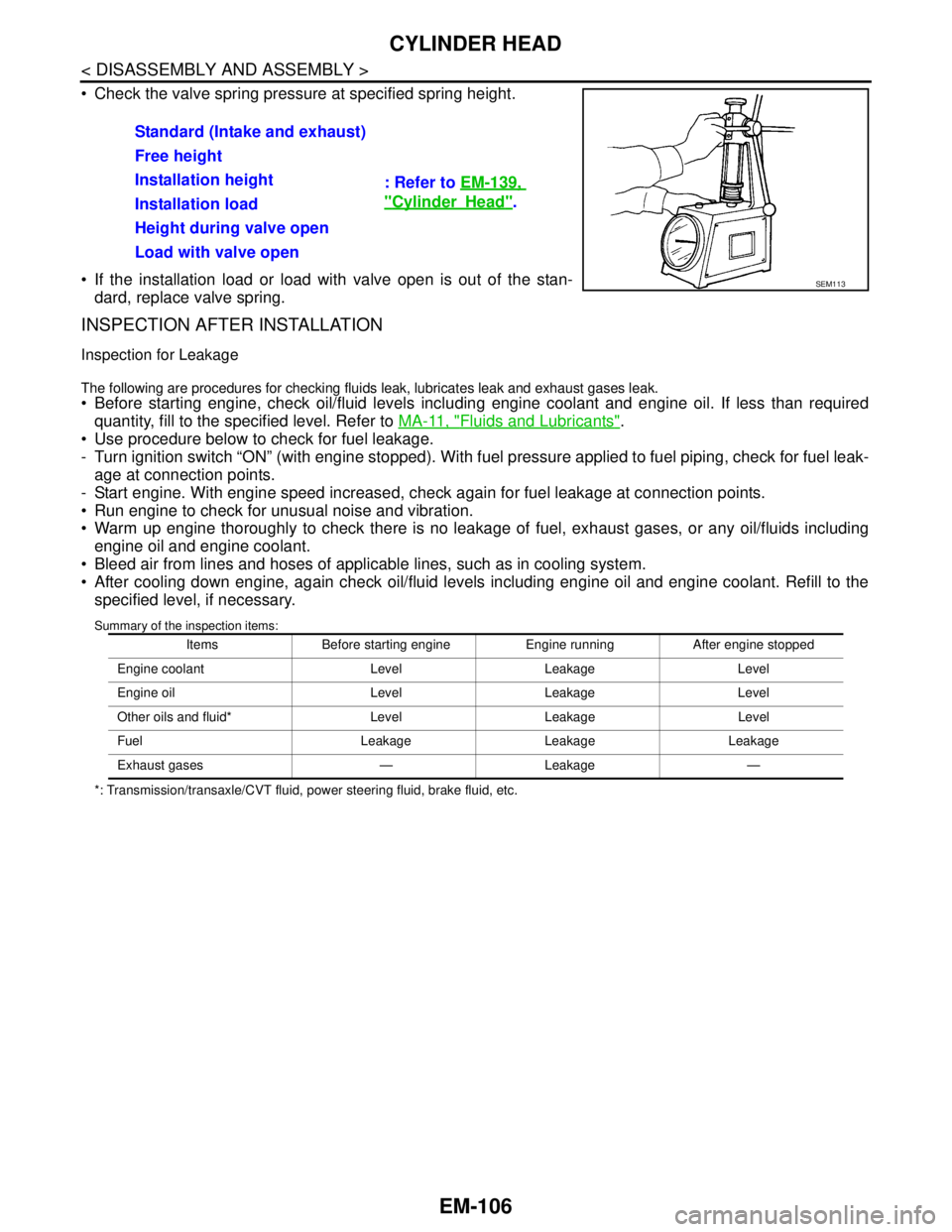
Check the valve spring pressure at specified spring height.
If the installation load or load with valve open is out of the stan-
dard, replace valve spring.
INSPECTION AFTER INSTALLATION
Inspection for Leakage
The following are procedures for checking fluids leak, lubricates leak and exhaust gases leak.
Before starting engine, check oil/fluid levels including engine coolant and engine oil. If less than required
quantity, fill to the specified level. Refer to MA-11, "
Fluids and Lubricants".
Use procedure below to check for fuel leakage.
- Turn ignition switch “ON” (with engine stopped). With fuel pressure applied to fuel piping, check for fuel leak-
age at connection points.
- Start engine. With engine speed increased, check again for fuel leakage at connection points.
Run engine to check for unusual noise and vibration.
Warm up engine thoroughly to check there is no leakage of fuel, exhaust gases, or any oil/fluids including
engine oil and engine coolant.
Bleed air from lines and hoses of applicable lines, such as in cooling system.
After cooling down engine, again check oil/fluid levels including engine oil and engine coolant. Refill to the
specified level, if necessary.
Summary of the inspection items:
*: Transmission/transaxle/CVT fluid, power steering fluid, brake fluid, etc.
Standard (Intake and exhaust)
: Refer to EM-139,
"CylinderHead". Free height
Installation height
Installation load
Height during valve open
Load with valve open
SEM113
Items Before starting engine Engine running After engine stopped
Engine coolant Level Leakage Level
Engine oil Level Leakage Level
Other oils and fluid* Level Leakage Level
Fuel Leakage Leakage Leakage
Exhaust gases — Leakage —
Page 2519 of 5121
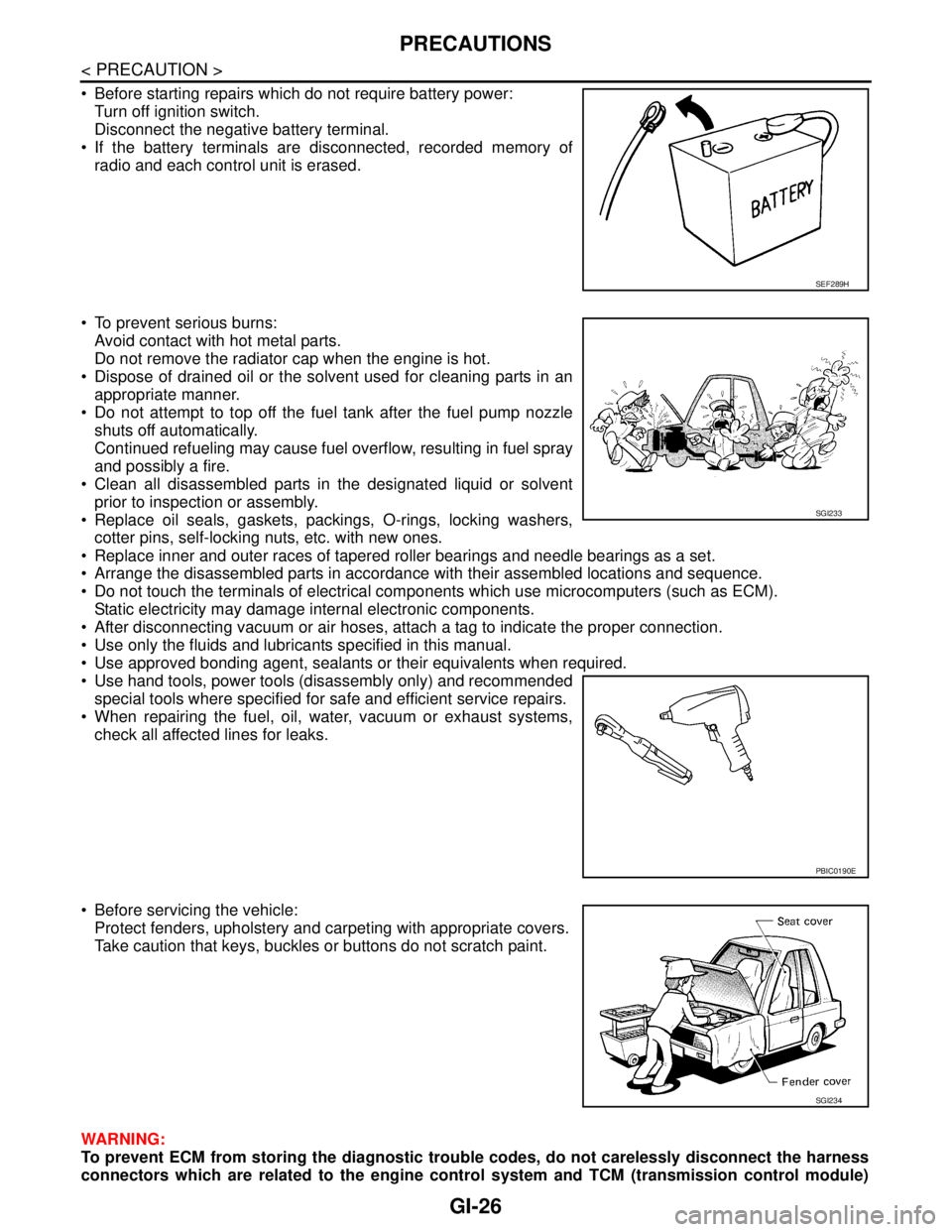
GI-26
< PRECAUTION >
PRECAUTIONS
Before starting repairs which do not require battery power:
Turn off ignition switch.
Disconnect the negative battery terminal.
If the battery terminals are disconnected, recorded memory of
radio and each control unit is erased.
To prevent serious burns:
Avoid contact with hot metal parts.
Do not remove the radiator cap when the engine is hot.
Dispose of drained oil or the solvent used for cleaning parts in an
appropriate manner.
Do not attempt to top off the fuel tank after the fuel pump nozzle
shuts off automatically.
Continued refueling may cause fuel overflow, resulting in fuel spray
and possibly a fire.
Clean all disassembled parts in the designated liquid or solvent
prior to inspection or assembly.
Replace oil seals, gaskets, packings, O-rings, locking washers,
cotter pins, self-locking nuts, etc. with new ones.
Replace inner and outer races of tapered roller bearings and needle bearings as a set.
Arrange the disassembled parts in accordance with their assembled locations and sequence.
Do not touch the terminals of electrical components which use microcomputers (such as ECM).
Static electricity may damage internal electronic components.
After disconnecting vacuum or air hoses, attach a tag to indicate the proper connection.
Use only the fluids and lubricants specified in this manual.
Use approved bonding agent, sealants or their equivalents when required.
Use hand tools, power tools (disassembly only) and recommended
special tools where specified for safe and efficient service repairs.
When repairing the fuel, oil, water, vacuum or exhaust systems,
check all affected lines for leaks.
Before servicing the vehicle:
Protect fenders, upholstery and carpeting with appropriate covers.
Take caution that keys, buckles or buttons do not scratch paint.
WARNING:
To prevent ECM from storing the diagnostic trouble codes, do not carelessly disconnect the harness
connectors which are related to the engine control system and TCM (transmission control module)
SEF289H
SGI233
PBIC0190E
SGI234
Page 3195 of 5121
PERIODIC MAINTENANCE
MA-7
< ON-VEHICLE MAINTENANCE >
C
D
E
F
G
H
I
J
K
L
MB
MAN
OA
(5) Replace spark plug when the spark plug gap exceeds 1.4 mm (0.055 in) even if within specified periodic replacement
mileage.
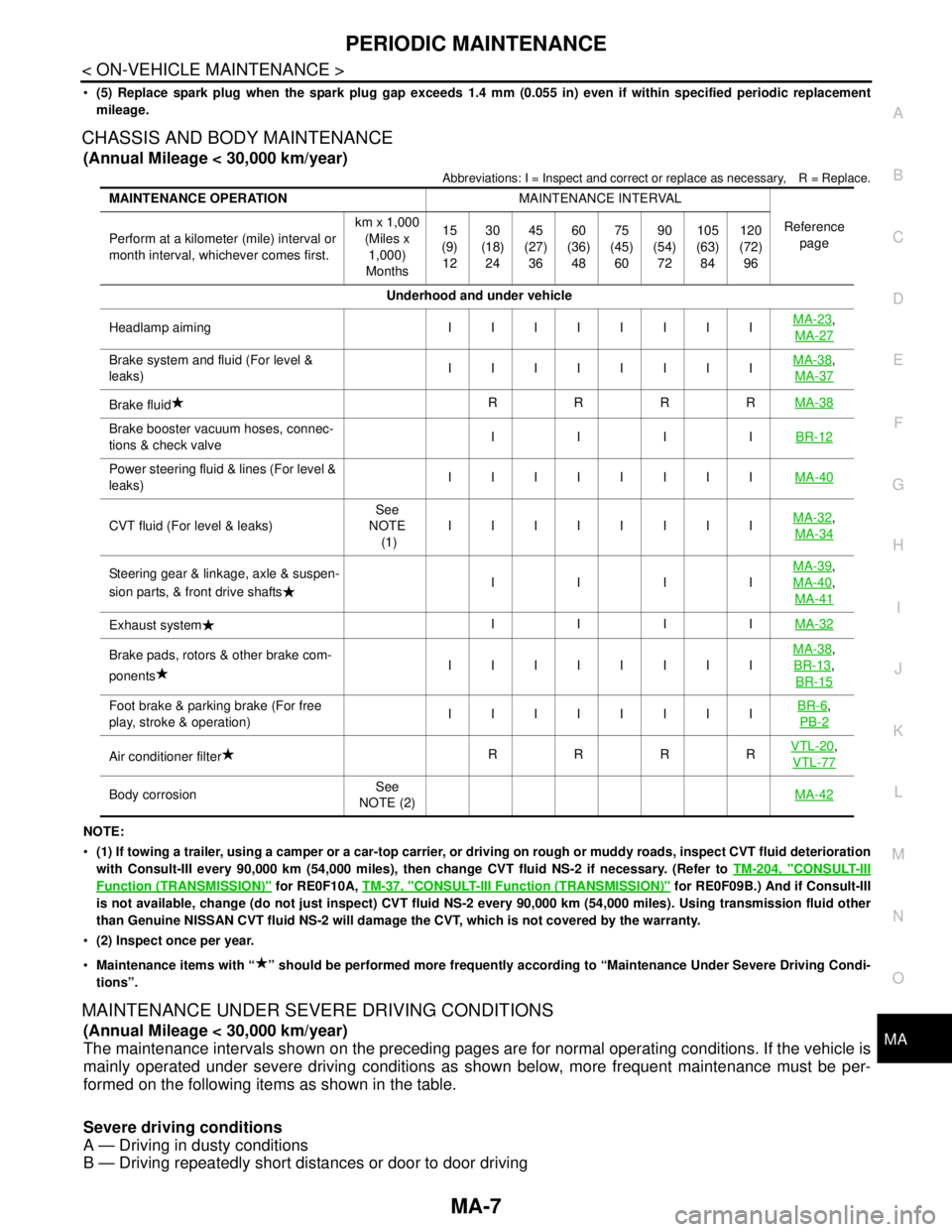
CHASSIS AND BODY MAINTENANCE
(Annual Mileage < 30,000 km/year)
Abbreviations: I = Inspect and correct or replace as necessary, R = Replace.
NOTE:
(1) If towing a trailer, using a camper or a car-top carrier, or driving on rough or muddy roads, inspect CVT fluid deterioration
with Consult-III every 90,000 km (54,000 miles), then change CVT fluid NS-2 if necessary. (Refer to TM-204, "
CONSULT-III
Function (TRANSMISSION)" for RE0F10A, TM-37, "CONSULT-III Function (TRANSMISSION)" for RE0F09B.) And if Consult-III
is not available, change (do not just inspect) CVT fluid NS-2 every 90,000 km (54,000 miles). Using transmission fluid other
than Genuine NISSAN CVT fluid NS-2 will damage the CVT, which is not covered by the warranty.
(2) Inspect once per year.
Maintenance items with “ ” should be performed more frequently according to “Maintenance Under Severe Driving Condi-
tions”.
MAINTENANCE UNDER SEVERE DRIVING CONDITIONS
(Annual Mileage < 30,000 km/year)
The maintenance intervals shown on the preceding pages are for normal operating conditions. If the vehicle is
mainly operated under severe driving conditions as shown below, more frequent maintenance must be per-
formed on the following items as shown in the table.
Severe driving conditions
A — Driving in dusty conditions
B — Driving repeatedly short distances or door to door driving
MAINTENANCE OPERATIONMAINTENANCE INTERVAL
Reference
page Perform at a kilometer (mile) interval or
month interval, whichever comes first.km x 1,000
(Miles x
1,000)
Months15
(9)
1230
(18)
2445
(27)
3660
(36)
4875
(45)
6090
(54)
72105
(63)
84120
(72)
96
Underhood and under vehicle
Headlamp aiming IIIIIIIIMA-23
,
MA-27
Brake system and fluid (For level &
leaks)IIIIIIIIMA-38,
MA-37
Brake fluidRRRRMA-38
Brake booster vacuum hoses, connec-
tions & check valveIIIIBR-12
Power steering fluid & lines (For level &
leaks)IIIIIIIIMA-40
CVT fluid (For level & leaks)See
NOTE
(1)IIIIIIIIMA-32,
MA-34
Steering gear & linkage, axle & suspen-
sion parts, & front drive shaftsIIIIMA-39,
MA-40
,
MA-41
Exhaust systemIIIIMA-32
Brake pads, rotors & other brake com-
ponentsIIIIIIIIMA-38,
BR-13
,
BR-15
Foot brake & parking brake (For free
play, stroke & operation)IIIIIIIIBR-6,
PB-2
Air conditioner filterRRRRVTL-20,
VTL-77
Body corrosionSee
NOTE (2)MA-42