2008 NISSAN TEANA coolant temperature
[x] Cancel search: coolant temperaturePage 1133 of 5121
CO-10
< ON-VEHICLE MAINTENANCE >
ENGINE COOLANT
6. Install air duct assembly and air cleaner cases (upper and lower) assembly. Refer to EM-26, "Exploded
View".
7. Install radiator cap.
8. Warm up engine until opening thermostat. Standard for warming-up time is approximately 10 minutes at
3,000 rpm.
Check thermostat opening condition by touching radiator hose (lower) to see a flow of warm water.
CAUTION:
Watch water temperature gauge so as not to overheat engine.
9. Stop the engine and cool down to less than approximately 50°C (122°F).
Cool down using fan to reduce the time.
If necessary, refill radiator up to filler neck with engine coolant.
CAUTION:
Never adhere the engine coolant to electronic equipments. (alternator etc.)
10. Refill reservoir tank to “MAX” level line with engine coolant.
11. Repeat steps 7 through 10 two or more times with radiator cap installed until engine coolant level no
longer drops.
12. Check cooling system for leakage with engine running.
13. Warm up the engine, and check for sound of engine coolant flow while running engine from idle up to
3,000 rpm with heater temperature controller set at several position between “COOL” and “WARM”.
Sound may be noticeable at heater unit.
14. Repeat step 13 three times.
15. If sound is heard, bleed air from cooling system by repeating step 5, and steps from 7 to 14 until engine
coolant level no longer drops.
FlushingINFOID:0000000003793169
1. Install reservoir tank if removed, and radiator drain plug.
CAUTION:
Be sure to clean drain plug and install with new O-ring.
If water drain plugs on cylinder block are removed, close and tighten them. Refer to EM-110, "
Dis-
assembly and Assembly".
2. Remove air duct assembly and air cleaner cases (upper and lower) assembly. Refer to EM-26, "
Exploded
View".
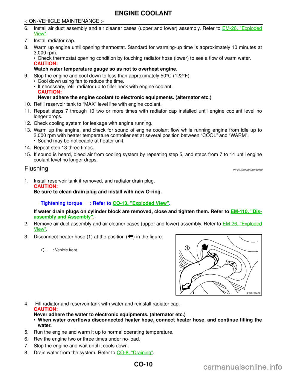
3. Disconnect heater hose (1) at the position ( ) in the figure.
4. Fill radiator and reservoir tank with water and reinstall radiator cap.
CAUTION:
Never adhere the water to electronic equipments. (alternator etc.)
When water overflows disconnected heater hose, connect heater hose, and continue filling the
water.
5. Run the engine and warm it up to normal operating temperature.
6. Rev the engine two or three times under no-load.
7. Stop the engine and wait until it cools down.
8. Drain water from the system. Refer to CO-8, "
Draining". Tightening torque : Refer to CO-13, "
Exploded View".
: Vehicle front
JPBIA2226ZZ
Page 1147 of 5121
CO-24
< ON-VEHICLE REPAIR >
WATER INLET AND THERMOSTAT ASSEMBLY
Inspection
INFOID:0000000003793184
INSPECTION AFTER REMOVAL
1. Check valve seating condition at ordinary room temperatures. It should seat tightly.
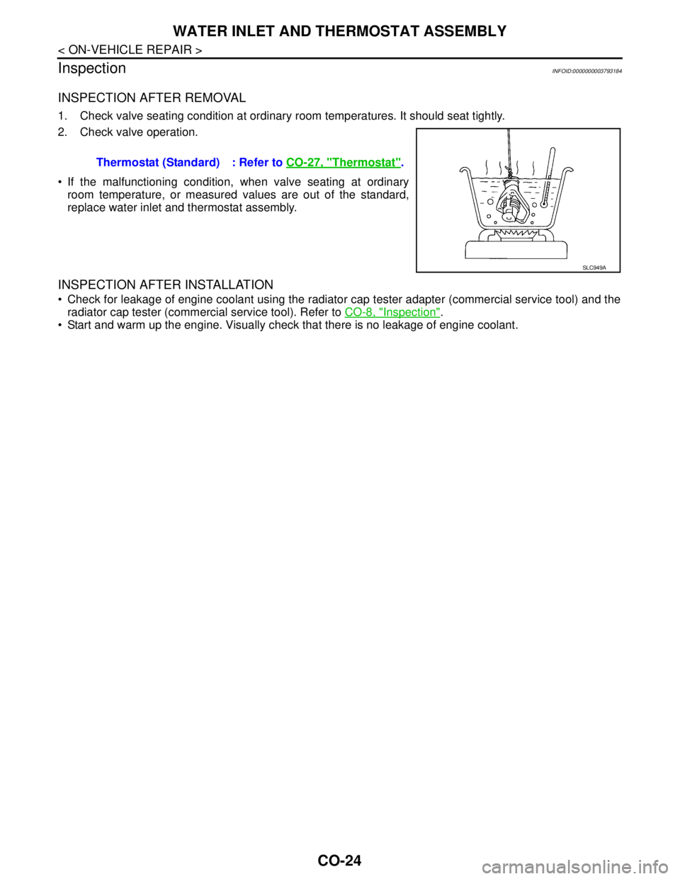
2. Check valve operation.
If the malfunctioning condition, when valve seating at ordinary
room temperature, or measured values are out of the standard,
replace water inlet and thermostat assembly.
INSPECTION AFTER INSTALLATION
Check for leakage of engine coolant using the radiator cap tester adapter (commercial service tool) and the
radiator cap tester (commercial service tool). Refer to CO-8, "
Inspection".
Start and warm up the engine. Visually check that there is no leakage of engine coolant. Thermostat (Standard) : Refer to CO-27, "
Thermostat".
SLC949A
Page 1148 of 5121
WATER OUTLET AND WATER PIPING
CO-25
< ON-VEHICLE REPAIR >
C
D
E
F
G
H
I
J
K
L
MA
CO
N
P O
WATER OUTLET AND WATER PIPING
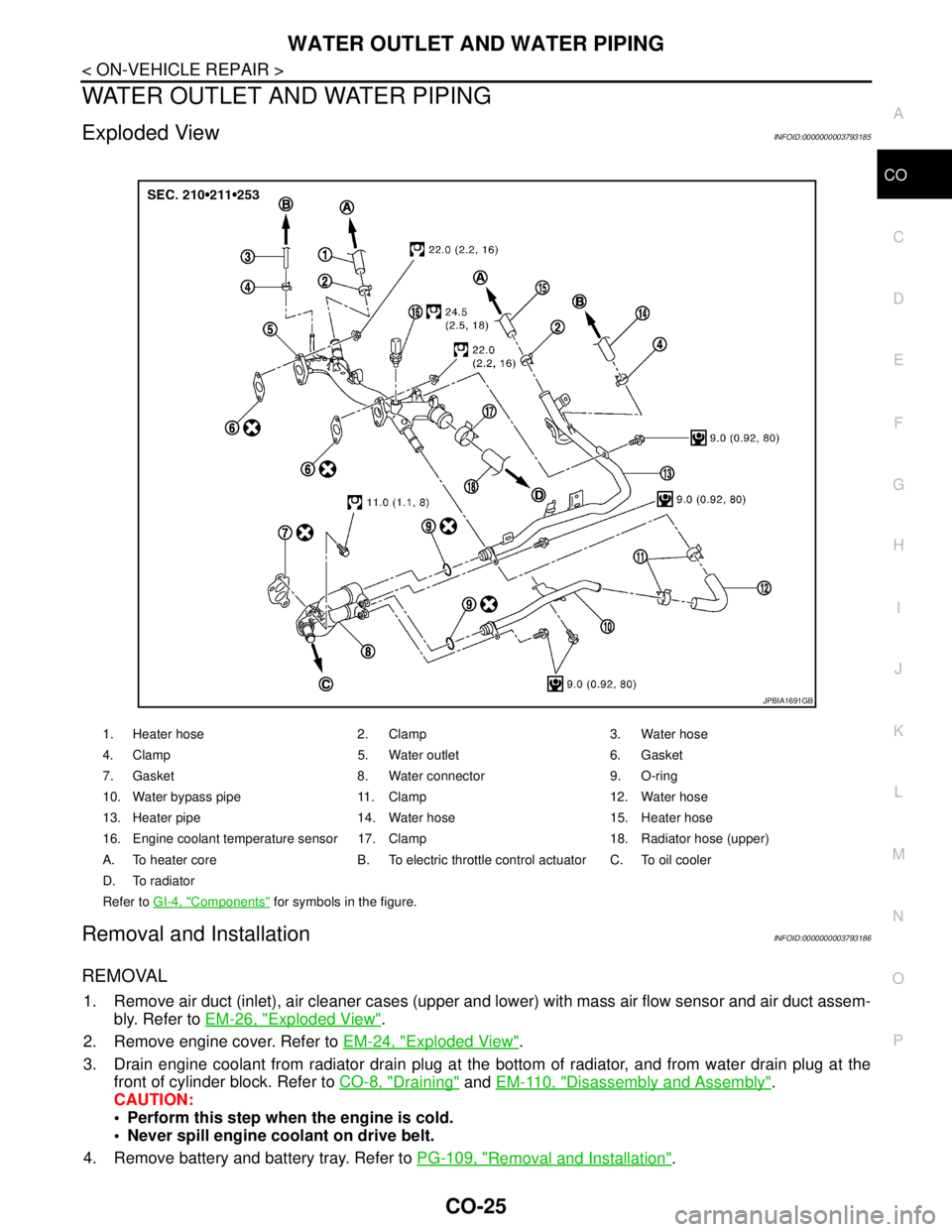
Exploded ViewINFOID:0000000003793185
Removal and InstallationINFOID:0000000003793186
REMOVAL
1. Remove air duct (inlet), air cleaner cases (upper and lower) with mass air flow sensor and air duct assem-
bly. Refer to EM-26, "
Exploded View".
2. Remove engine cover. Refer to EM-24, "
Exploded View".
3. Drain engine coolant from radiator drain plug at the bottom of radiator, and from water drain plug at the
front of cylinder block. Refer to CO-8, "
Draining" and EM-110, "Disassembly and Assembly".
CAUTION:
Perform this step when the engine is cold.
Never spill engine coolant on drive belt.
4. Remove battery and battery tray. Refer to PG-109, "
Removal and Installation".
1. Heater hose 2. Clamp 3. Water hose
4. Clamp 5. Water outlet 6. Gasket
7. Gasket 8. Water connector 9. O-ring
10. Water bypass pipe 11. Clamp 12. Water hose
13. Heater pipe 14. Water hose 15. Heater hose
16. Engine coolant temperature sensor 17. Clamp 18. Radiator hose (upper)
A. To heater core B. To electric throttle control actuator C. To oil cooler
D. To radiator
Refer to GI-4, "
Components" for symbols in the figure.
JPBIA1691GB
Page 1149 of 5121
CO-26
< ON-VEHICLE REPAIR >
WATER OUTLET AND WATER PIPING
5. Remove CVT fluid charging pipe and CVT fluid level gauge. Refer to TM-332, "Exploded View" (VQ25DE)
or TM-168, "
Exploded View" (VQ35DE).
6. Move CVT control cable aside. Refer to TM-319, "
Exploded View" (VQ25DE) or TM-157, "Exploded View"
(VQ35DE).
7. Remove vacuum pipe (front) mounting bolt from water outlet. Refer to EM-67, "
Exploded View".
8. Remove radiator hose (upper) from water outlet.
9. Remove water hoses and heater hoses.
10. Disconnect harness connectors, and move harness to aside.
11. Remove engine coolant temperature sensor as necessary.
CAUTION:
Be careful not to damage engine coolant temperature sensor.
12. Remove water outlet, heater pipe, water bypass pipe and water connector.
INSTALLATION
Note the following, and install in the reverse order of removal.
Securely insert each hose, and install clamp at a position where it does not interfere with the pipe bulge.
When inserting water bypass pipe and heater pipe into water connector, apply neutral detergent to O-ring.
InspectionINFOID:0000000003793187
INSPECTION AFTER INSTALLATION
Check for leakage of engine coolant using the radiator cap tester adapter (commercial service tool) and the
radiator cap tester (commercial service tool). Refer to CO-8, "
Inspection".
Start and warm up the engine. Visually check that there is no leakage of engine coolant.
Page 1150 of 5121
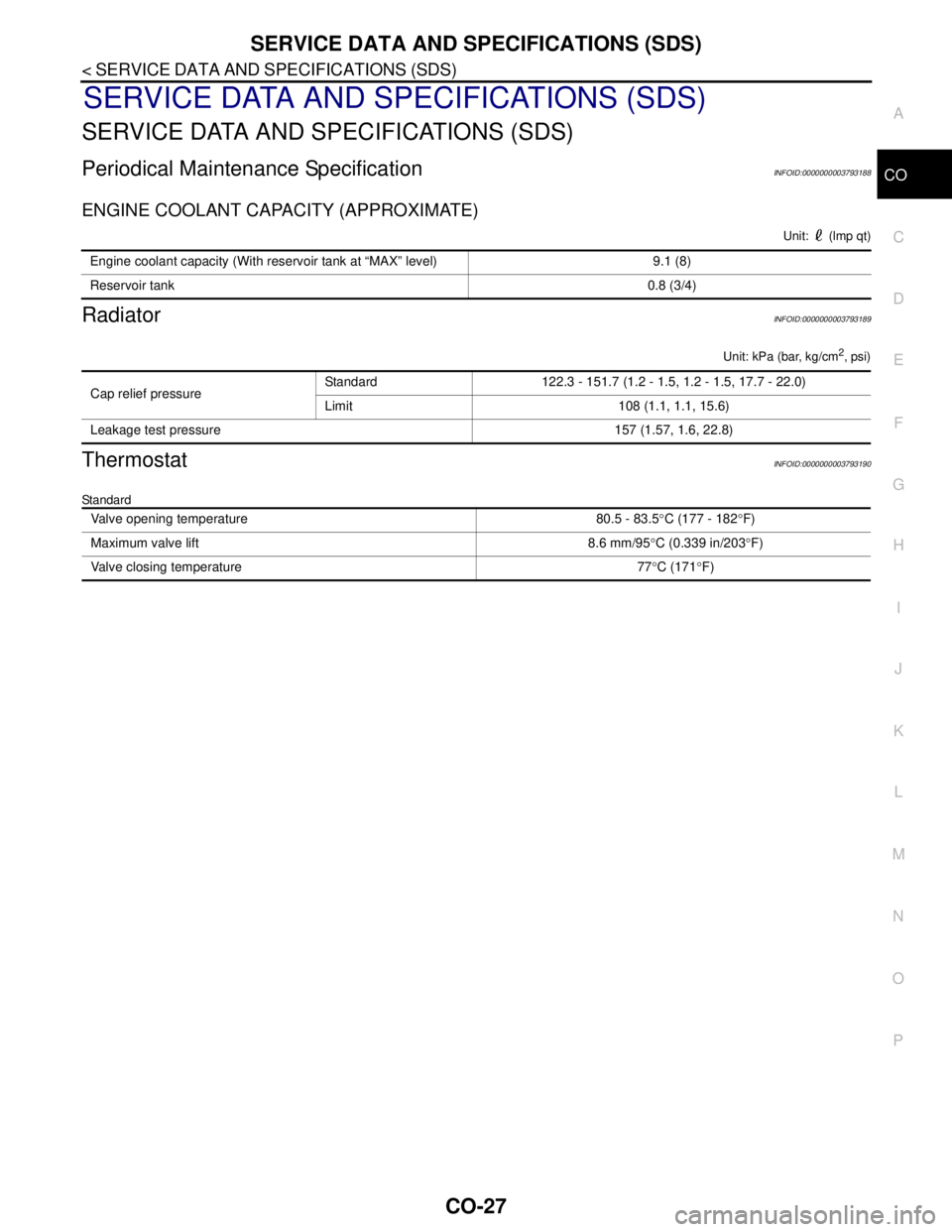
SERVICE DATA AND SPECIFICATIONS (SDS)
CO-27
< SERVICE DATA AND SPECIFICATIONS (SDS)
C
D
E
F
G
H
I
J
K
L
MA
CO
N
P O
SERVICE DATA AND SPECIFICATIONS (SDS)
SERVICE DATA AND SPECIFICATIONS (SDS)
Periodical Maintenance SpecificationINFOID:0000000003793188
ENGINE COOLANT CAPACITY (APPROXIMATE)
Unit: (lmp qt)
RadiatorINFOID:0000000003793189
Unit: kPa (bar, kg/cm2, psi)
ThermostatINFOID:0000000003793190
Standard
Engine coolant capacity (With reservoir tank at “MAX” level) 9.1 (8)
Reservoir tank0.8 (3/4)
Cap relief pressureStandard 122.3 - 151.7 (1.2 - 1.5, 1.2 - 1.5, 17.7 - 22.0)
Limit 108 (1.1, 1.1, 15.6)
Leakage test pressure 157 (1.57, 1.6, 22.8)
Valve opening temperature 80.5 - 83.5°C (177 - 182°F)
Maximum valve lift 8.6 mm/95°C (0.339 in/203°F)
Valve closing temperature 77°C (171°F)
Page 1472 of 5121
![NISSAN TEANA 2008 Service Manual INSPECTION AND ADJUSTMENT
EC-11
< BASIC INSPECTION >[VQ25DE, VQ35DE]
C
D
E
F
G
H
I
J
K
L
MA
EC
N
P O
INSPECTION AND ADJUSTMENT
BASIC INSPECTION
BASIC INSPECTION : Special Repair RequirementINFOID:0000 NISSAN TEANA 2008 Service Manual INSPECTION AND ADJUSTMENT
EC-11
< BASIC INSPECTION >[VQ25DE, VQ35DE]
C
D
E
F
G
H
I
J
K
L
MA
EC
N
P O
INSPECTION AND ADJUSTMENT
BASIC INSPECTION
BASIC INSPECTION : Special Repair RequirementINFOID:0000](/manual-img/5/57391/w960_57391-1471.png)
INSPECTION AND ADJUSTMENT
EC-11
< BASIC INSPECTION >[VQ25DE, VQ35DE]
C
D
E
F
G
H
I
J
K
L
MA
EC
N
P O
INSPECTION AND ADJUSTMENT
BASIC INSPECTION
BASIC INSPECTION : Special Repair RequirementINFOID:0000000003856444
1.INSPECTION START
1. Check service records for any recent repairs that may indicate a related malfunction, or a current need for
scheduled maintenance.
2. Open engine hood and check the following:
- Harness connectors for improper connections
- Wiring harness for improper connections, pinches and cut
- Vacuum hoses for splits, kinks and improper connections
- Hoses and ducts for leaks
- Air cleaner clogging
- Gasket
3. Confirm that electrical or mechanical loads are not applied.
- Head lamp switch is OFF.
- Air conditioner switch is OFF.
- Rear window defogger switch is OFF.
- Steering wheel is in the straight-ahead position, etc.
4. Start engine and warm it up until engine coolant temperature
indicator points the middle of gauge.
Ensure engine stays below 1,000 rpm.
5. Run engine at about 2,000 rpm for about 2 minutes under no
load.
6. Check that no DTC is displayed with CONSULT-III or GST.
Are any DTCs detected?
YES >> GO TO 2.
NO >> GO TO 3.
2.REPAIR OR REPLACE
Repair or replace components as necessary according to corresponding Diagnostic Procedure.
>> GO TO 3
3.CHECK TARGET IDLE SPEED
1. Run engine at about 2,000 rpm for about 2 minutes under no load.
SEF983U
SEF976U
SEF977U
Page 1477 of 5121
![NISSAN TEANA 2008 Service Manual EC-16
< BASIC INSPECTION >[VQ25DE, VQ35DE]
INSPECTION AND ADJUSTMENT
THROTTLE VALVE CLOSED POSITION LEARNING
THROTTLE VALVE CLOSED POSITION LEARNING : DescriptionINFOID:0000000003856455
Throttle Valve NISSAN TEANA 2008 Service Manual EC-16
< BASIC INSPECTION >[VQ25DE, VQ35DE]
INSPECTION AND ADJUSTMENT
THROTTLE VALVE CLOSED POSITION LEARNING
THROTTLE VALVE CLOSED POSITION LEARNING : DescriptionINFOID:0000000003856455
Throttle Valve](/manual-img/5/57391/w960_57391-1476.png)
EC-16
< BASIC INSPECTION >[VQ25DE, VQ35DE]
INSPECTION AND ADJUSTMENT
THROTTLE VALVE CLOSED POSITION LEARNING
THROTTLE VALVE CLOSED POSITION LEARNING : DescriptionINFOID:0000000003856455
Throttle Valve Closed Position Learning is an operation to learn the fully closed position of the throttle valve by
monitoring the throttle position sensor output signal. It must be performed each time harness connector of
electric throttle control actuator or ECM is disconnected.
THROTTLE VALVE CLOSED POSITION LEARNING : Special Repair Requirement
INFOID:0000000003856456
1.START
1. Check that accelerator pedal is fully released.
2. Turn ignition switch ON.
3. Turn ignition switch OFF and wait at least 10 seconds.
Check that throttle valve moves during above 10 seconds by confirming the operating sound.
>> END
IDLE AIR VOLUME LEARNING
IDLE AIR VOLUME LEARNING : DescriptionINFOID:0000000003856457
Idle Air Volume Learning is a function of ECM to learn the idle air volume that keeps engine idle speed within
the specific range. It must be performed under the following conditions:
Each time electric throttle control actuator or ECM is replaced.
Idle speed or ignition timing is out of specification.
IDLE AIR VOLUME LEARNING : Special Repair RequirementINFOID:0000000003856458
1.PRECONDITIONING
Before performing Idle Air Volume Learning, check that all of the following conditions are satisfied.
Learning will be cancelled if any of the following conditions are missed for even a moment.
Battery voltage: More than 12.9 V (At idle)
Engine coolant temperature: 70 - 100°C (158 - 212°F)
Selector lever: P or N
Electric load switch: OFF
(Air conditioner, head lamp, rear window defogger)
-For vehicle equipped with daytime light systems, perform one of the following procedures before
starting engine not to illuminate headlamps.
Apply parking brake
Set lighting switch to the 1st position
Steering wheel: Neutral (Straight-ahead position)
Vehicle speed: Stopped
Transmission: Warmed-up
- With CONSULT-III: Drive vehicle until “ATF TEMP SEN” in “DATA MONITOR” mode of “CVT” system indi-
cates less than 0.9 V.
- Without CONSULT-III: Drive vehicle for 10 minutes.
Will CONSULT-III be used?
YES >> GO TO 2.
NO >> GO TO 3.
2.PERFORM IDLE AIR VOLUME LEARNING
With CONSULT-III
1. Perform EC-15, "
ACCELERATOR PEDAL RELEASED POSITION LEARNING : Special Repair Require-
ment".
2. Perform EC-16, "
THROTTLE VALVE CLOSED POSITION LEARNING : Special Repair Requirement".
3. Start engine and warm it up to normal operating temperature.
4. Select “IDLE AIR VOL LEARN” in “WORK SUPPORT” mode.
5. Touch “START” and wait 20 seconds.
Page 1481 of 5121
![NISSAN TEANA 2008 Service Manual EC-20
< FUNCTION DIAGNOSIS >[VQ25DE, VQ35DE]
ENGINE CONTROL SYSTEM
System Description
INFOID:0000000003856462
ECM performs various controls such as fuel injection control and ignition timing control.
NISSAN TEANA 2008 Service Manual EC-20
< FUNCTION DIAGNOSIS >[VQ25DE, VQ35DE]
ENGINE CONTROL SYSTEM
System Description
INFOID:0000000003856462
ECM performs various controls such as fuel injection control and ignition timing control.](/manual-img/5/57391/w960_57391-1480.png)
EC-20
< FUNCTION DIAGNOSIS >[VQ25DE, VQ35DE]
ENGINE CONTROL SYSTEM
System Description
INFOID:0000000003856462
ECM performs various controls such as fuel injection control and ignition timing control.
Component Parts LocationINFOID:0000000003856463
1. Intake valve timing control solenoid
valve (bank 1)2. Intake valve timing control solenoid
valve (bank 2)3. Electronic controlled engine mount
control solenoid valve
4. Fuel injector (bank 2) 5. Cooling fan motor-2 6. A/F sensor 1 (bank 2)
7. Ignition coil (with power transistor)
and spark plug (bank 2)8. Camshaft position sensor (PHASE)
(bank 2)9. Crankshaft position sensor (POS)
10. Engine coolant temperature sensor 11. Cooling fan motor-1 12. ECM
13. Refrigerant pressure sensor 14. Battery current sensor 15. IPDM E/R
16. Mass air flow sensor (with intake air
temperature sensor)17. Electric throttle control actuator 18. Power valve actuator 2 (VQ35DE
models)
19. EVAP canister purge volume control
solenoid valve20. Camshaft position sensor (PHASE)
(bank 1)21. Ignition coil (with power transistor)
and spark plug (bank 1)
22. A/F sensor 1 (bank 1) 23. Fuel injector (bank 1) 24. VIAS control solenoid valve 1 and 2
(VQ35DE models)
25. Power valve actuator 1
JMBIA1373ZZ