2008 NISSAN TEANA engine oil capacity
[x] Cancel search: engine oil capacityPage 1951 of 5121
EM-76
< DISASSEMBLY AND ASSEMBLY >
ENGINE STAND SETTING
DISASSEMBLY AND ASSEMBLY
ENGINE STAND SETTING
SettingINFOID:0000000003802278
NOTE:
Explained here is how to disassemble with engine stand supporting transaxle surface. When using different
type of engine stand, note with difference in steps and etc.
1. Remove the engine assembly from the vehicle. Refer to EM-67, "
Exploded View".
2. Remove the parts that may restrict installation of engine to widely use engine stand.
NOTE:
The procedure is described assuming that you use a widely use engine stand holding the surface, to
which transmission is installed.
Remove drive plate. Fix crankshaft pulley with the pulley holder (commercial service tool), and remove
mounting bolts.
Loosen mounting bolts in diagonal order.
Check for deformation or damage drive plate.
CAUTION:
Never disassemble drive plate.
Never place drive plate with signal plate facing down.
When handling signal plate, take care not to damage or scratch it.
Handle signal plate in a manner that prevents it from becoming magnetized.
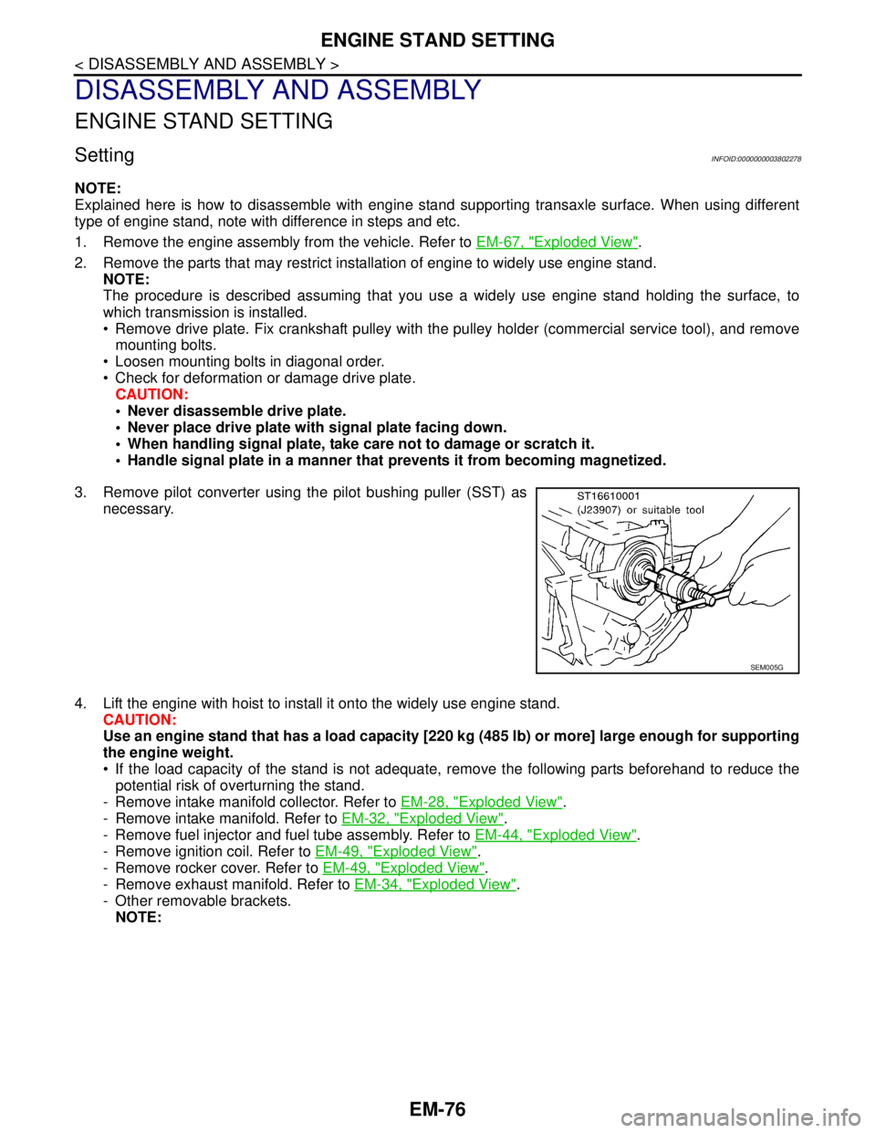
3. Remove pilot converter using the pilot bushing puller (SST) as
necessary.
4. Lift the engine with hoist to install it onto the widely use engine stand.
CAUTION:
Use an engine stand that has a load capacity [220 kg (485 lb) or more] large enough for supporting
the engine weight.
If the load capacity of the stand is not adequate, remove the following parts beforehand to reduce the
potential risk of overturning the stand.
- Remove intake manifold collector. Refer to EM-28, "
Exploded View".
- Remove intake manifold. Refer to EM-32, "
Exploded View".
- Remove fuel injector and fuel tube assembly. Refer to EM-44, "
Exploded View".
- Remove ignition coil. Refer to EM-49, "
Exploded View".
- Remove rocker cover. Refer to EM-49, "
Exploded View".
- Remove exhaust manifold. Refer to EM-34, "
Exploded View".
- Other removable brackets.
NOTE:
SEM005G
Page 2628 of 5121
SERVICE DATA AND SPECIFICATIONS (SDS)
HA-59
< SERVICE DATA AND SPECIFICATIONS (SDS)
C
D
E
F
G
H
J
K
L
MA
B
HA
N
O
P
SERVICE DATA AND SPECIFICATIONS (SDS)
SERVICE DATA AND SPECIFICATIONS (SDS)
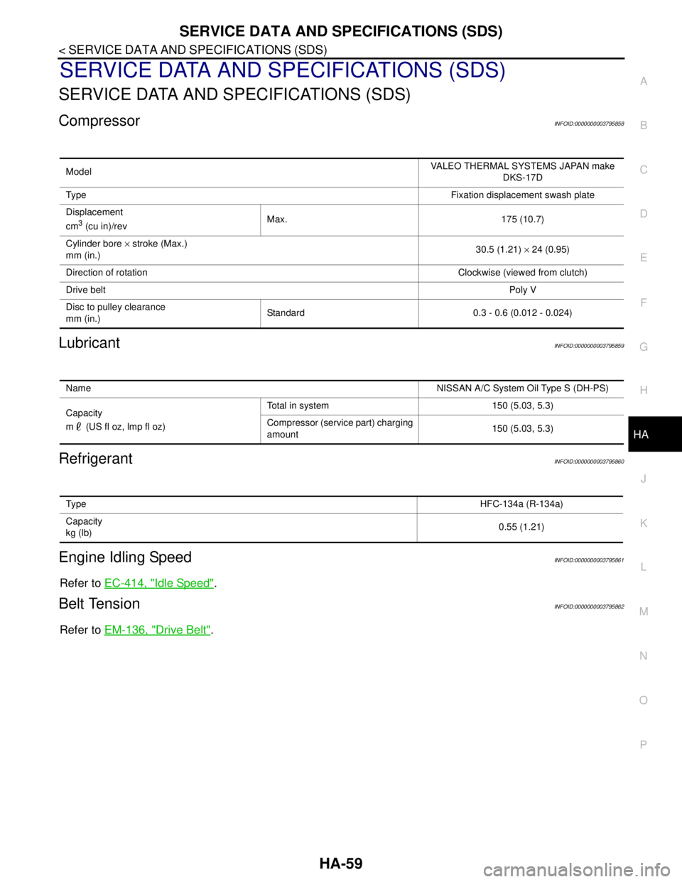
CompressorINFOID:0000000003795858
LubricantINFOID:0000000003795859
RefrigerantINFOID:0000000003795860
Engine Idling SpeedINFOID:0000000003795861
Refer to EC-414, "Idle Speed".
Belt TensionINFOID:0000000003795862
Refer to EM-136, "Drive Belt".
ModelVALEO THERMAL SYSTEMS JAPAN make
DKS-17D
Ty p eFixation displacement swash plate
Displacement
cm
3 (cu in)/revMax. 175 (10.7)
Cylinder bore × stroke (Max.)
mm (in.)30.5 (1.21) × 24 (0.95)
Direction of rotationClockwise (viewed from clutch)
Drive beltPoly V
Disc to pulley clearance
mm (in.)Standard 0.3 - 0.6 (0.012 - 0.024)
NameNISSAN A/C System Oil Type S (DH-PS)
Capacity
m (US fl oz, lmp fl oz)Total in system 150 (5.03, 5.3)
Compressor (service part) charging
amount150 (5.03, 5.3)
Ty p eHFC-134a (R-134a)
Capacity
kg (lb)0.55 (1.21)
Page 3181 of 5121
ENGINE OIL
LU-9
< ON-VEHICLE MAINTENANCE >
C
D
E
F
G
H
I
J
K
L
MA
LU
N
P O
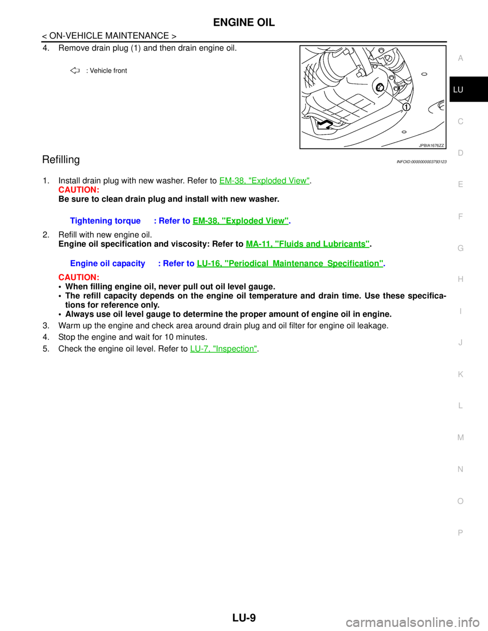
4. Remove drain plug (1) and then drain engine oil.
RefillingINFOID:0000000003793123
1. Install drain plug with new washer. Refer to EM-38, "Exploded View".
CAUTION:
Be sure to clean drain plug and install with new washer.
2. Refill with new engine oil.
Engine oil specification and viscosity: Refer to MA-11, "
Fluids and Lubricants".
CAUTION:
When filling engine oil, never pull out oil level gauge.
The refill capacity depends on the engine oil temperature and drain time. Use these specifica-
tions for reference only.
Always use oil level gauge to determine the proper amount of engine oil in engine.
3. Warm up the engine and check area around drain plug and oil filter for engine oil leakage.
4. Stop the engine and wait for 10 minutes.
5. Check the engine oil level. Refer to LU-7, "
Inspection".
: Vehicle front
JPBIA1676ZZ
Tightening torque : Refer to EM-38, "Exploded View".
Engine oil capacity : Refer to LU-16, "
PeriodicalMaintenanceSpecification".
Page 3188 of 5121

LU-16
< SERVICE DATA AND SPECIFICATIONS (SDS)
SERVICE DATA AND SPECIFICATIONS (SDS)
SERVICE DATA AND SPECIFICATIONS (SDS)
SERVICE DATA AND SPECIFICATIONS (SDS)
Periodical Maintenance SpecificationINFOID:0000000003793134
ENGINE OIL CAPACITY (APPROXIMATE)
Unit: (lmp qt)
Engine Oil PressureINFOID:0000000003793135
Unit: kPa (bar, kg/cm2, psi)
*: Engine oil temperature at 80°C (176°F)
Oil PumpINFOID:0000000003793136
Unit: mm (in)
Regulator ValveINFOID:0000000003793137
Unit: mm (in)
Drain and refill With oil filter change 4.6 (4)
Without oil filter change 4.3 (3-3/4)
Dry engine (Overhaul)5.3 (4-5/8)
Engine speed Approximate discharge pressure*
Idle speed More than 98 (0.98, 1.0, 14)
2,000 rpm More than 294 (2.94, 3.0, 43)
Clearance between oil pump outer rotor and oil pump body 0.114 - 0.260 (0.0045 - 0.0102)
Tip clearance between oil pump inner rotor and oil pump outer rotor Below 0.180 (0.0071)
Side clearance between oil pump inner rotor and oil pump body 0.030 - 0.070 (0.0012 - 0.0028)
Side clearance between oil pump outer rotor and oil pump body 0.050 - 0.110 (0.0020 - 0.0043)
Oil pump inner rotor to oil pump body clearance 0.045 - 0.091 (0.0018 - 0.0036)
Regulator valve to oil pump body clearance 0.040 - 0.097 (0.0016 - 0.0038)
Page 3199 of 5121

RECOMMENDED FLUIDS AND LUBRICANTS
MA-11
< ON-VEHICLE MAINTENANCE >
C
D
E
F
G
H
I
J
K
L
MB
MAN
OA
RECOMMENDED FLUIDS AND LUBRICANTS
Fluids and LubricantsINFOID:0000000003858223
*1: For further details, see “SAE Viscosity Number”.
*2: Use Genuine NISSAN Engine Coolant or equivalent in its quality, in order to avoid possible aluminum corrosion within the engine
cooling system caused by the use of non-genuine engine coolant.
Note that any repairs for the incidents within the engine cooling system while using non-genuine engine coolant may not be
covered by the warranty even if such incidents occurred during the warranty period.
*3: Using transmission fluid other than Genuine NISSAN CVT fluid NS-2 will damage the CVT, which is not covered by the war-
ranty.
*4: DEXRON
™ VI type ATF can be used.
*5: Never mix different types of fluids (DOT3 and DOT4).
SAE Viscosity NumberINFOID:0000000003858224
GASOLINE ENGINE
5W-30 is preferable.
Capacity (Approximate)
Recommended Fluids/Lubricants
LiterImp mea-
sure
Engine oil
Drain and refillWith oil filter change 4.6 4 qt
Genuine NISSAN engine oil
*1
API grade SL or SM*1
ILSAC grade GF-3 or GF-4*1
ACEA A1/B1, A3/B3, A3/B4, A5/B5, C2 or C3*1
Without oil filter
change4.3 3-3/4 qt
Dry engine (engine overhaul) 5.3 4-5/8 qt
Cooling system (with reservoir) 9.1 8 qt
Genuine NISSAN Engine Coolant or equivalent
in its quality
*2Reservoir tank 0.8 3/4 qt
CVT fluidRE0F10A 8.3 7-1/4 qt
Genuine NISSAN CVT Fluid NS-2
*3
RE0F09B 10.2 9 qt
Power steering fluid 1.0 7/8 qt
Genuine NISSAN PSF or equivalent
*4
Brake fluid — —Genuine NISSAN brake fluid, or equivalent DOT
3 or DOT4 (US FMVSS No. 116)*5
Multi-purpose grease — — NLGI No. 2 (Lithium soap base)
Page 3207 of 5121
ENGINE MAINTENANCE
MA-19
< ON-VEHICLE MAINTENANCE >
C
D
E
F
G
H
I
J
K
L
MB
MAN
OA
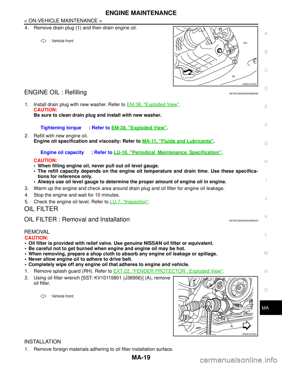
4. Remove drain plug (1) and then drain engine oil.
ENGINE OIL : RefillingINFOID:0000000003862458
1. Install drain plug with new washer. Refer to EM-38, "Exploded View".
CAUTION:
Be sure to clean drain plug and install with new washer.
2. Refill with new engine oil.
Engine oil specification and viscosity: Refer to MA-11, "
Fluids and Lubricants".
CAUTION:
When filling engine oil, never pull out oil level gauge.
The refill capacity depends on the engine oil temperature and drain time. Use these specifica-
tions for reference only.
Always use oil level gauge to determine the proper amount of engine oil in engine.
3. Warm up the engine and check area around drain plug and oil filter for engine oil leakage.
4. Stop the engine and wait for 10 minutes.
5. Check the engine oil level. Refer to LU-7, "
Inspection".
OIL FILTER
OIL FILTER : Removal and InstallationINFOID:0000000003862459
REMOVAL
CAUTION:
Oil filter is provided with relief valve. Use genuine NISSAN oil filter or equivalent.
Be careful not to get burned when engine and engine oil may be hot.
When removing, prepare a shop cloth to absorb any engine oil leakage or spillage.
Never allow engine oil to adhere to drive belt.
Completely wipe off any engine oil that adheres to engine and vehicle.
1. Remove splash guard (RH). Refer to EXT-22, "
FENDER PROTECTOR : Exploded View".
2. Using oil filter wrench [SST: KV10115801 (J38956)] (A), remove
oil filter.
INSTALLATION
1. Remove foreign materials adhering to oil filter installation surface.
: Vehicle front
JPBIA1676ZZ
Tightening torque : Refer to EM-38, "Exploded View".
Engine oil capacity : Refer to LU-16, "
PeriodicalMaintenanceSpecification".
: Vehicle front
JPBIA1678ZZ
Page 3221 of 5121
CHASSIS MAINTENANCE
MA-33
< ON-VEHICLE MAINTENANCE >
C
D
E
F
G
H
I
J
K
L
MB
MAN
OA
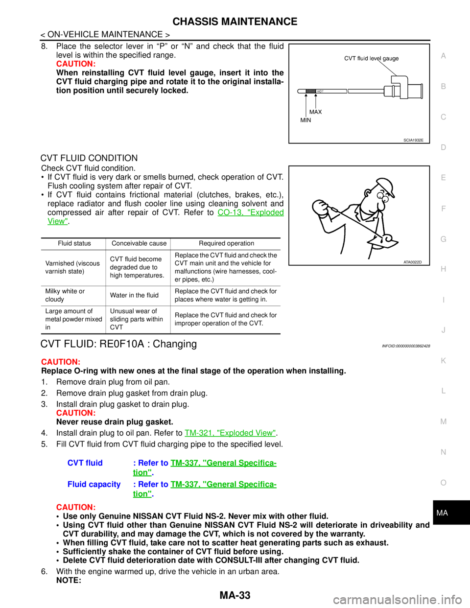
8. Place the selector lever in “P” or “N” and check that the fluid
level is within the specified range.
CAUTION:
When reinstalling CVT fluid level gauge, insert it into the
CVT fluid charging pipe and rotate it to the original installa-
tion position until securely locked.
CVT FLUID CONDITION
Check CVT fluid condition.
If CVT fluid is very dark or smells burned, check operation of CVT.
Flush cooling system after repair of CVT.
If CVT fluid contains frictional material (clutches, brakes, etc.),
replace radiator and flush cooler line using cleaning solvent and
compressed air after repair of CVT. Refer to CO-13, "
Exploded
View".
CVT FLUID: RE0F10A : ChangingINFOID:0000000003862428
CAUTION:
Replace O-ring with new ones at the final stage of the operation when installing.
1. Remove drain plug from oil pan.
2. Remove drain plug gasket from drain plug.
3. Install drain plug gasket to drain plug.
CAUTION:
Never reuse drain plug gasket.
4. Install drain plug to oil pan. Refer to TM-321, "
Exploded View".
5. Fill CVT fluid from CVT fluid charging pipe to the specified level.
CAUTION:
Use only Genuine NISSAN CVT Fluid NS-2. Never mix with other fluid.
Using CVT fluid other than Genuine NISSAN CVT Fluid NS-2 will deteriorate in driveability and
CVT durability, and may damage the CVT, which is not covered by the warranty.
When filling CVT fluid, take care not to scatter heat generating parts such as exhaust.
Sufficiently shake the container of CVT fluid before using.
Delete CVT fluid deterioration date with CONSULT-III after changing CVT fluid.
6. With the engine warmed up, drive the vehicle in an urban area.
NOTE:
SCIA1932E
Fluid status Conceivable cause Required operation
Varnished (viscous
varnish state)CVT fluid become
degraded due to
high temperatures.Replace the CVT fluid and check the
CVT main unit and the vehicle for
malfunctions (wire harnesses, cool-
er pipes, etc.)
Milky white or
cloudyWater in the fluidReplace the CVT fluid and check for
places where water is getting in.
Large amount of
metal powder mixed
inUnusual wear of
sliding parts within
CVTReplace the CVT fluid and check for
improper operation of the CVT.
ATA0022D
CVT fluid : Refer to TM-337, "General Specifica-
tion".
Fluid capacity : Refer to TM-337, "
General Specifica-
tion".
Page 3223 of 5121
CHASSIS MAINTENANCE
MA-35
< ON-VEHICLE MAINTENANCE >
C
D
E
F
G
H
I
J
K
L
MB
MAN
OA
CVT FLUID CONDITION
Check CVT fluid condition.
If CVT fluid is very dark or smells burned, check operation of CVT.
Flush cooling system after repair of CVT.
If CVT fluid contains frictional material (clutches, brakes, etc.),
replace radiator and flush cooler line using cleaning solvent and
compressed air after repair of CVT. Refer to CO-13, "
Exploded
View".
CVT FLUID: RE0F09B : ChangingINFOID:0000000003862430
CAUTION:
Replace O-ring with new ones at the final stage of the operation when installing.
1. Remove drain plug from oil pan.
2. Remove drain plug gasket from drain plug.
3. Install drain plug gasket to drain plug.
CAUTION:
Never reuse drain plug gasket.
4. Install drain plug to oil pan.
5. Fill CVT fluid from CVT fluid charging pipe to the specified level.
CAUTION:
Use only Genuine NISSAN CVT Fluid NS-2. Never mix with other fluid.
Using CVT fluid other than Genuine NISSAN CVT Fluid NS-2 will deteriorate in driveability and
CVT durability, and may damage the CVT, which is not covered by the warranty.
When filling CVT fluid, take care not to scatter heat generating parts such as exhaust.
Sufficiently shake the container of CVT fluid before using.
Delete CVT fluid deterioration date with CONSULT-III after changing CVT fluid. Refer to TM-37,
"CONSULT-III Function (TRANSMISSION)".
6. With the engine warmed up, drive the vehicle in an urban area.
NOTE:
When ambient temperature is 20°C (68°F), it takes about 10 minutes for the CVT fluid to warm up to 50 to
80°C (122 to 176°F).
7. Check CVT fluid level and condition.
8. Repeat steps 1 to 5 if CVT fluid has been contaminated.
WHEELS (BONDING WEIGHT TYPE)
WHEELS (BONDING WEIGHT TYPE) : AdjustmentINFOID:0000000003911590
BALANCING WHEELS (BONDING WEIGHT TYPE)
Fluid status Conceivable cause Required operation
Varnished (viscous
varnish state)CVT fluid becomes
degraded due to
high temperatures.Replace the CVT fluid and check the
CVT main unit and the vehicle for
malfunctions (wire harnesses, cool-
er pipes, etc.)
Milky white or
cloudyWater in the fluidReplace the CVT fluid and check for
places where water is getting in.
Large amount of
metal powder mixed
inUnusual wear of
sliding parts within
CVTReplace the CVT fluid and check for
improper operation of the CVT.
ATA0022D
Drain plug – tightening torque : Refer to TM-159, "Exploded View"
CVT fluid : Refer to TM-174, "General Specification".
Fluid capacity : Refer to TM-174, "
General Specification".