2008 NISSAN TEANA maintenance
[x] Cancel search: maintenancePage 1134 of 5121

ENGINE COOLANT
CO-11
< ON-VEHICLE MAINTENANCE >
C
D
E
F
G
H
I
J
K
L
MA
CO
N
P O
9. Repeat steps 1 through 8 until clear water begins to drain from radiator.
Page 1135 of 5121

CO-12
< ON-VEHICLE MAINTENANCE >
RADIATOR
RADIATOR
RADIATOR CAP
RADIATOR CAP : InspectionINFOID:0000000003793170
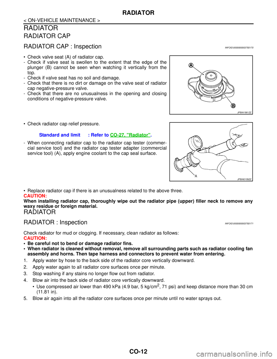
Check valve seat (A) of radiator cap.
- Check if valve seat is swollen to the extent that the edge of the
plunger (B) cannot be seen when watching it vertically from the
top.
- Check if valve seat has no soil and damage.
- Check that there is no dirt or damage on the valve seat of radiator
cap negative-pressure valve.
- Check that there are no unusualness in the opening and closing
conditions of negative-pressure valve.
Check radiator cap relief pressure.
- When connecting radiator cap to the radiator cap tester (commer-
cial service tool) and the radiator cap tester adapter (commercial
service tool) (A), apply engine coolant to the cap seal surface.
Replace radiator cap if there is an unusualness related to the above three.
CAUTION:
When installing radiator cap, thoroughly wipe out the radiator pipe (upper) filler neck to remove any
waxy residue or foreign material.
RADIATOR
RADIATOR : InspectionINFOID:0000000003793171
Check radiator for mud or clogging. If necessary, clean radiator as follows:
CAUTION:
Be careful not to bend or damage radiator fins.
When radiator is cleaned without removal, remove all surrounding parts such as radiator cooling fan
assembly and horns. Then tape harness and connectors to prevent water from entering.
1. Apply water by hose to the back side of the radiator core vertically downward.
2. Apply water again to all radiator core surfaces once per minute.
3. Stop washing if any stains no longer flow out from radiator.
4. Blow air into the back side of radiator core vertically downward.
Use compressed air lower than 490 kPa (4.9 bar, 5 kg/cm
2, 71 psi) and keep distance more than 30 cm
(11.81 in).
5. Blow air again into all the radiator core surfaces once per minute until no water sprays out.
JPBIA1961ZZ
Standard and limit : Refer to CO-27, "Radiator".
JPBIA0109ZZ
Page 1150 of 5121

SERVICE DATA AND SPECIFICATIONS (SDS)
CO-27
< SERVICE DATA AND SPECIFICATIONS (SDS)
C
D
E
F
G
H
I
J
K
L
MA
CO
N
P O
SERVICE DATA AND SPECIFICATIONS (SDS)
SERVICE DATA AND SPECIFICATIONS (SDS)
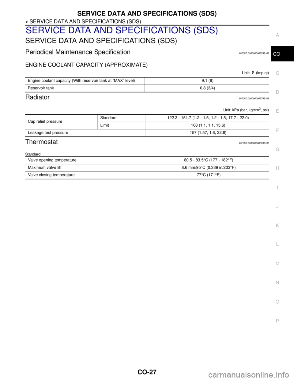
Periodical Maintenance SpecificationINFOID:0000000003793188
ENGINE COOLANT CAPACITY (APPROXIMATE)
Unit: (lmp qt)
RadiatorINFOID:0000000003793189
Unit: kPa (bar, kg/cm2, psi)
ThermostatINFOID:0000000003793190
Standard
Engine coolant capacity (With reservoir tank at “MAX” level) 9.1 (8)
Reservoir tank0.8 (3/4)
Cap relief pressureStandard 122.3 - 151.7 (1.2 - 1.5, 1.2 - 1.5, 17.7 - 22.0)
Limit 108 (1.1, 1.1, 15.6)
Leakage test pressure 157 (1.57, 1.6, 22.8)
Valve opening temperature 80.5 - 83.5°C (177 - 182°F)
Maximum valve lift 8.6 mm/95°C (0.339 in/203°F)
Valve closing temperature 77°C (171°F)
Page 1213 of 5121

PRECAUTIONS
DEF-63
< PRECAUTION >
C
D
E
F
G
H
I
J
K
MA
B
DEF
N
O
P
PRECAUTION
PRECAUTIONS
Precaution for Supplemental Restraint System (SRS) "AIR BAG" and "SEAT BELT
PRE-TENSIONER"
INFOID:0000000003940045
The Supplemental Restraint System such as “AIR BAG” and “SEAT BELT PRE-TENSIONER”, used along
with a front seat belt, helps to reduce the risk or severity of injury to the driver and front passenger for certain
types of collision. Information necessary to service the system safely is included in the “SRS AIRBAG” and
“SEAT BELT” of this Service Manual.
WARNING:
• To avoid rendering the SRS inoperative, which could increase the risk of personal injury or death in
the event of a collision which would result in air bag inflation, all maintenance must be performed by
an authorized NISSAN/INFINITI dealer.
Improper maintenance, including incorrect removal and installation of the SRS, can lead to personal
injury caused by unintentional activation of the system. For removal of Spiral Cable and Air Bag
Module, see the “SRS AIRBAG”.
Never use electrical test equipment on any circuit related to the SRS unless instructed to in this Ser-
vice Manual. SRS wiring harnesses can be identified by yellow and/or orange harnesses or harness
connectors.
Page 1404 of 5121
![NISSAN TEANA 2008 Service Manual DLK-188
< PRECAUTION >[WITH INTELLIGENT KEY SYSTEM]
PRECAUTIONS
PRECAUTION
PRECAUTIONS
Precaution for Supplemental Restraint System (SRS) "AIR BAG" and "SEAT BELT
PRE-TENSIONER"
INFOID:00000000039419 NISSAN TEANA 2008 Service Manual DLK-188
< PRECAUTION >[WITH INTELLIGENT KEY SYSTEM]
PRECAUTIONS
PRECAUTION
PRECAUTIONS
Precaution for Supplemental Restraint System (SRS) "AIR BAG" and "SEAT BELT
PRE-TENSIONER"
INFOID:00000000039419](/manual-img/5/57391/w960_57391-1403.png)
DLK-188
< PRECAUTION >[WITH INTELLIGENT KEY SYSTEM]
PRECAUTIONS
PRECAUTION
PRECAUTIONS
Precaution for Supplemental Restraint System (SRS) "AIR BAG" and "SEAT BELT
PRE-TENSIONER"
INFOID:0000000003941991
The Supplemental Restraint System such as “AIR BAG” and “SEAT BELT PRE-TENSIONER”, used along
with a front seat belt, helps to reduce the risk or severity of injury to the driver and front passenger for certain
types of collision. Information necessary to service the system safely is included in the “SRS AIRBAG” and
“SEAT BELT” of this Service Manual.
WARNING:
To avoid rendering the SRS inoperative, which could increase the risk of personal injury or death in
the event of a collision which would result in air bag inflation, all maintenance must be performed by
an authorized NISSAN/INFINITI dealer.
Improper maintenance, including incorrect removal and installation of the SRS, can lead to personal
injury caused by unintentional activation of the system. For removal of Spiral Cable and Air Bag
Module, see the “SRS AIRBAG”.
Never use electrical test equipment on any circuit related to the SRS unless instructed to in this Ser-
vice Manual. SRS wiring harnesses can be identified by yellow and/or orange harnesses or harness
connectors.
Precaution for Procedure without Cowl Top CoverINFOID:0000000003795058
When performing the procedure after removing cowl top cover, cover
the lower end of windshield with urethane, etc.
Precaution Necessary for Steering Wheel Rotation after Battery Disconnect
INFOID:0000000003845516
NOTE:
Before removing and installing any control units, first turn the push-button ignition switch to the LOCK posi-
tion, then disconnect both battery cables.
After finishing work, confirm that all control unit connectors are connected properly, then re-connect both
battery cables.
Always use CONSULT-III to perform self-diagnosis as a part of each function inspection after finishing work.
If a DTC is detected, perform trouble diagnosis according to self-diagnosis results.
This vehicle is equipped with a push-button ignition switch and a steering lock unit.
If the battery is disconnected or discharged, the steering wheel will lock and cannot be turned.
If turning the steering wheel is required with the battery disconnected or discharged, follow the procedure
below before starting the repair operation.
OPERATION PROCEDURE
1. Connect both battery cables.
NOTE:
Supply power using jumper cables if battery is discharged.
2. Turn the push-button ignition switch to ACC position.
(At this time, the steering lock will be released.)
3. Disconnect both battery cables. The steering lock will remain released with both battery cables discon-
nected and the steering wheel can be turned.
4. Perform the necessary repair operation.
PIIB3706J
Page 1467 of 5121

EC-6
Description .............................................................404
PRECAUTION ............................................405
PRECAUTIONS ...............................................405
Precaution for Supplemental Restraint System
(SRS) "AIR BAG" and "SEAT BELT PRE-TEN-
SIONER" ................................................................
405
Precautions For Xenon Headlamp Service ...........405
Precaution for Procedure without Cowl Top Cover ..405
On Board Diagnostic (OBD) System of Engine
and CVT ................................................................
405
General Precautions ..............................................406
PREPARATION ..........................................410
PREPARATION ...............................................410
Special Service Tools ............................................410
Commercial Service Tools .....................................410
ON-VEHICLE MAINTENANCE .................411
FUEL PRESSURE ............................................411
Inspection ..............................................................411
ON-VEHICLE REPAIR ..............................413
EVAPORATIVE EMISSION SYSTEM ..............413
Inspection ..............................................................413
SERVICE DATA AND SPECIFICATIONS
(SDS) .........................................................
414
SERVICE DATA AND SPECIFICATIONS
(SDS) ................................................................
414
Idle Speed .............................................................414
Ignition Timing .......................................................414
Calculated Load Value ..........................................414
Mass Air Flow Sensor ...........................................414
Page 1472 of 5121
![NISSAN TEANA 2008 Service Manual INSPECTION AND ADJUSTMENT
EC-11
< BASIC INSPECTION >[VQ25DE, VQ35DE]
C
D
E
F
G
H
I
J
K
L
MA
EC
N
P O
INSPECTION AND ADJUSTMENT
BASIC INSPECTION
BASIC INSPECTION : Special Repair RequirementINFOID:0000 NISSAN TEANA 2008 Service Manual INSPECTION AND ADJUSTMENT
EC-11
< BASIC INSPECTION >[VQ25DE, VQ35DE]
C
D
E
F
G
H
I
J
K
L
MA
EC
N
P O
INSPECTION AND ADJUSTMENT
BASIC INSPECTION
BASIC INSPECTION : Special Repair RequirementINFOID:0000](/manual-img/5/57391/w960_57391-1471.png)
INSPECTION AND ADJUSTMENT
EC-11
< BASIC INSPECTION >[VQ25DE, VQ35DE]
C
D
E
F
G
H
I
J
K
L
MA
EC
N
P O
INSPECTION AND ADJUSTMENT
BASIC INSPECTION
BASIC INSPECTION : Special Repair RequirementINFOID:0000000003856444
1.INSPECTION START
1. Check service records for any recent repairs that may indicate a related malfunction, or a current need for
scheduled maintenance.
2. Open engine hood and check the following:
- Harness connectors for improper connections
- Wiring harness for improper connections, pinches and cut
- Vacuum hoses for splits, kinks and improper connections
- Hoses and ducts for leaks
- Air cleaner clogging
- Gasket
3. Confirm that electrical or mechanical loads are not applied.
- Head lamp switch is OFF.
- Air conditioner switch is OFF.
- Rear window defogger switch is OFF.
- Steering wheel is in the straight-ahead position, etc.
4. Start engine and warm it up until engine coolant temperature
indicator points the middle of gauge.
Ensure engine stays below 1,000 rpm.
5. Run engine at about 2,000 rpm for about 2 minutes under no
load.
6. Check that no DTC is displayed with CONSULT-III or GST.
Are any DTCs detected?
YES >> GO TO 2.
NO >> GO TO 3.
2.REPAIR OR REPLACE
Repair or replace components as necessary according to corresponding Diagnostic Procedure.
>> GO TO 3
3.CHECK TARGET IDLE SPEED
1. Run engine at about 2,000 rpm for about 2 minutes under no load.
SEF983U
SEF976U
SEF977U
Page 1564 of 5121
![NISSAN TEANA 2008 Service Manual ON BOARD DIAGNOSTIC (OBD) SYSTEM
EC-103
< FUNCTION DIAGNOSIS >[VQ25DE, VQ35DE]
C
D
E
F
G
H
I
J
K
L
MA
EC
N
P O
The 1st trip DTC (whose number is the same as the DTC number) is displayed for the latest NISSAN TEANA 2008 Service Manual ON BOARD DIAGNOSTIC (OBD) SYSTEM
EC-103
< FUNCTION DIAGNOSIS >[VQ25DE, VQ35DE]
C
D
E
F
G
H
I
J
K
L
MA
EC
N
P O
The 1st trip DTC (whose number is the same as the DTC number) is displayed for the latest](/manual-img/5/57391/w960_57391-1563.png)
ON BOARD DIAGNOSTIC (OBD) SYSTEM
EC-103
< FUNCTION DIAGNOSIS >[VQ25DE, VQ35DE]
C
D
E
F
G
H
I
J
K
L
MA
EC
N
P O
The 1st trip DTC (whose number is the same as the DTC number) is displayed for the latest self-diagnostic
result obtained. If the ECM memory was cleared previously, and the 1st trip DTC did not recur, the 1st trip DTC
will not be displayed.
If a malfunction is detected during the 1st trip, the 1st trip DTC is saved in the ECM memory. The MI will not
illuminate (two trip detection logic). If the same malfunction is not detected in the 2nd trip (meeting the required
driving pattern), the 1st trip DTC is cleared from the ECM memory. If the same malfunction is detected in the
2nd trip, both the 1st trip DTC and DTC are saved in the ECM memory and the MI illuminates. In other words,
the DTC is stored in the ECM memory and the MI illuminates when the same malfunction occurs in two con-
secutive trips. If a 1st trip DTC is stored and a non-diagnostic operation is performed between the 1st and 2nd
trips, only the 1st trip DTC will continue to be stored. For malfunctions that blink or illuminate the MI during the
1st trip, the DTC and 1st trip DTC are stored in the ECM memory.
Procedures for clearing the DTC and the 1st trip DTC from the ECM memory are described in “How to Erase
DTC and 1st Trip DTC”.
For malfunctions in which 1st trip DTCs are displayed, refer to “EMISSION-RELATED DIAGNOSTIC INFOR-
MATION ITEMS”. These items are required by legal regulations to continuously monitor the system/compo-
nent. In addition, the items monitored non-continuously are also displayed on CONSULT-III.
1st trip DTC is specified in Service $07 of ISO 15031-5. 1st trip DTC detection occurs without illuminating the
MI and therefore does not warn the driver of a malfunction. However, 1st trip DTC detection will not prevent
the vehicle from being tested, for example during Inspection/Maintenance (I/M) tests.
When a 1st trip DTC is detected, check, print out or write down and erase (1st trip) DTC and Freeze Frame
data as specified in Work Flow procedure Step 2, refer to EC-7, "
Work Flow". Then perform DTC Confirmation
Procedure or Component Function Check to try to duplicate the malfunction. If the malfunction is duplicated,
the item requires repair.
Freeze Frame Data and 1st Trip Freeze Frame Data
The ECM records the driving conditions such as fuel system status, calculated load value, engine coolant tem-
perature, short-term fuel trim, long-term fuel trim, engine speed, vehicle speed, absolute throttle position, base
fuel schedule and intake air temperature at the moment a malfunction is detected.
Data which are stored in the ECM memory, along with the 1st trip DTC, are called 1st trip freeze frame data.
The data, stored together with the DTC data, are called freeze frame data and displayed on CONSULT-III or
GST. The 1st trip freeze frame data can only be displayed on the CONSULT-III screen, not on the GST.
Only one set of freeze frame data (either 1st trip freeze frame data or freeze frame data) can be stored in the
ECM. 1st trip freeze frame data is stored in the ECM memory along with the 1st trip DTC. There is no priority
for 1st trip freeze frame data and it is updated each time a different 1st trip DTC is detected. However, once
freeze frame data (2nd trip detection/MI on) is stored in the ECM memory, 1st trip freeze frame data is no
longer stored. Remember, only one set of freeze frame data can be stored in the ECM. The ECM has the fol-
lowing priorities to update the data.
For example, the EGR malfunction (Priority: 2) was detected and the freeze frame data was saved in the 2nd
trip. After that when the misfire (Priority: 1) is detected in another trip, the freeze frame data will be updated
from the EGR malfunction to the misfire. The 1st trip freeze frame data is updated each time a different mal-
function is detected. There is no priority for 1st trip freeze frame data. However, once freeze frame data is
stored in the ECM memory, 1st trip freeze data is no longer stored (because only one freeze frame data or 1st
trip freeze frame data can be stored in the ECM). If freeze frame data is stored in the ECM memory and freeze
frame data with the same priority occurs later, the first (original) freeze frame data remains unchanged in the
ECM memory.
Both 1st trip freeze frame data and freeze frame data (along with the DTCs) are cleared when the ECM mem-
ory is erased. Procedures for clearing the ECM memory are described in “How to Erase DTC and 1st Trip
DTC”.
How to Read DTC and 1st Trip DTC
With CONSULT-III
With GST
CONSULT-III or GST (Generic Scan Tool) Examples: P0340, P0850, P1148, etc.
These DTCs are prescribed by ISO 15031-6.
Priority Items
1Freeze frame data Misfire — DTC: P0300 - P0306
Fuel Injection System Function — DTC: P0171, P0172, P0174, P0175
2 Except the above items (Includes CVT related items)
3 1st trip freeze frame data