2008 NISSAN TEANA fuel cap release
[x] Cancel search: fuel cap releasePage 1687 of 5121
![NISSAN TEANA 2008 Service Manual EC-226
< COMPONENT DIAGNOSIS >[VQ25DE, VQ35DE]
P0420, P0430 THREE WAY CATALYST FUNCTION
P0420, P0430 THREE WAY CATALYST FUNCTION
DTC LogicINFOID:0000000003856631
DTC DETECTION LOGIC
The ECM monitors t NISSAN TEANA 2008 Service Manual EC-226
< COMPONENT DIAGNOSIS >[VQ25DE, VQ35DE]
P0420, P0430 THREE WAY CATALYST FUNCTION
P0420, P0430 THREE WAY CATALYST FUNCTION
DTC LogicINFOID:0000000003856631
DTC DETECTION LOGIC
The ECM monitors t](/manual-img/5/57391/w960_57391-1686.png)
EC-226
< COMPONENT DIAGNOSIS >[VQ25DE, VQ35DE]
P0420, P0430 THREE WAY CATALYST FUNCTION
P0420, P0430 THREE WAY CATALYST FUNCTION
DTC LogicINFOID:0000000003856631
DTC DETECTION LOGIC
The ECM monitors the switching frequency ratio of air fuel ratio (A/F)
sensor 1 and heated oxygen sensor 2.
A three way catalyst (manifold) with high oxygen storage capacity
will indicate a low switching frequency of heated oxygen sensor 2.
As oxygen storage capacity decreases, the heated oxygen sensor 2
switching frequency will increase.
When the frequency ratio of A/F sensor 1 and heated oxygen sensor
2 approaches a specified limit value, the three way catalyst (mani-
fold) malfunction is diagnosed.
DTC CONFIRMATION PROCEDURE
1.INSPECTION START
Will CONSULT-III be used?
Will CONSULT-III be used?
YES >> GO TO 2.
NO >> GO TO 7.
2.PRECONDITIONING
If DTC Confirmation Procedure has been previously conducted, always turn ignition switch OFF and wait at
least 10 seconds before conducting the next test.
TESTING CONDITION:
Do not hold engine speed for more than the specified minutes below.
>> GO TO 3.
3.PERFORM DTC CONFIRMATION PROCEDURE-I
With CONSULT-III
1. Turn ignition switch ON and select “DATA MONITOR” mode with CONSULT-III.
2. Start engine and warm it up to the normal operating temperature.
3. Turn ignition switch OFF and wait at least 10 seconds.
4. Start engine and keep the engine speed between 3,500 and 4,000 rpm for at least 1 minute under no load.
5. Let engine idle for 1 minute.
6. Check that “COOLAN TEMP/S” indicates more than 70°C (158°F).
If not, warm up engine and go to next step when “COOLAN TEMP/S” indication reaches to 70°C (158°F).
7. Open engine hood.
8. Select “DTC & SRT CONFIRMATION” then “SRT WORK SUPPORT” mode with CONSULT-III.
9. Rev engine between 2,000 and 3,000 rpm and hold it for 3 consecutive minutes then release the acceler-
ator pedal completely.
10. Check the indication of “CATALYST”.
Which is displayed on CONSULT-III screen?
PBIB2055E
DTC No. Trouble diagnosis name DTC detecting condition Possible cause
P0420Catalyst system efficien-
cy below threshold
(bank 1) Three way catalyst (manifold) does not oper-
ate properly.
Three way catalyst (manifold) does not have
enough oxygen storage capacity. Three way catalyst (manifold)
Exhaust tube
Intake air leaks
Fuel injector
Fuel injector leaks
Spark plug
Improper ignition timing P0430Catalyst system efficien-
cy below threshold
(bank 2)
Page 1881 of 5121

EM-6
< PRECAUTION >
PRECAUTIONS
3. Disconnect both battery cables. The steering lock will remain released with both battery cables discon-
nected and the steering wheel can be turned.
4. Perform the necessary repair operation.
5. When the repair work is completed, re-connect both battery cables. With the brake pedal released, turn
the push-button ignition switch from ACC position to ON position, then to LOCK position. (The steering
wheel will lock when the push-button ignition switch is turned to LOCK position.)
6. Perform self-diagnosis check of all control units using CONSULT-III.
Precaution for Drain Engine Coolant and Engine OilINFOID:0000000003802227
Drain engine coolant and engine oil when the engine is cooled.
Precaution for Disconnecting Fuel PipingINFOID:0000000003802228
Before starting work, check no fire or spark producing items are in the work area.
Release fuel pressure before disconnecting and disassembly.
After disconnecting pipes, plug openings to stop fuel leakage.
Precaution for Removal and DisassemblyINFOID:0000000003802229
When instructed to use SST, use the specified tools. Always be careful to work safely, avoid forceful or unin-
structed operations.
Exercise maximum care to avoid damage to mating or sliding surfaces.
Dowel pins are used for several parts alignment. When replacing and reassembling parts with dowel pins,
check that dowel pins are installed in the original position.
Cover openings of engine system with a tape or the equivalent, if necessary, to seal out foreign materials.
Mark and arrange disassembly parts in an organized way for easy troubleshooting and reassembly.
When loosening nuts and bolts, as a basic rule, start with the one furthest outside, then the one diagonally
opposite, and so on. If the order of loosening is specified, do exactly as specified. Power tools may be used
in the step.
Precaution for Inspection, Repair and ReplacementINFOID:0000000003802230
Before repairing or replacing, thoroughly inspect parts. Inspect new replacement parts in the same way, and
replace if necessary.
Precaution for Assembly and InstallationINFOID:0000000003802231
Use torque wrench to tighten bolts or nuts to specification.
When tightening nuts and bolts, as a basic rule, equally tighten in several different steps starting with the
ones in center, then ones on inside and outside diagonally in this order. If the order of tightening is specified,
do exactly as specified.
Replace with new gasket, packing, oil seal or O-ring.
Dowel pins are used for several parts alignment. When replacing and reassembling parts with dowel pins,
check that dowel pins are installed in the original position.
Thoroughly wash, clean, and air-blow each part. Carefully check engine oil or engine coolant passages for
any restriction and blockage.
Avoid damaging sliding or mating surfaces. Completely remove foreign materials such as cloth lint or dust.
Before assembly, oil sliding surfaces well.
Release air within route when refilling after draining engine coolant.
After repairing, start the engine and increase engine speed to check engine coolant, fuel, engine oil, and
exhaust gases for leakage.
Precaution for Angle TighteningINFOID:0000000003802232
Use the angle wrench [SST: KV10112100 (BT8653-A)] for the final tightening of the following engine parts:
- Cylinder head bolts
- Main bearing cap bolts
- Connecting rod cap bolts
- Crankshaft pulley bolt (No the angle wrench is required as bolt flange is provided with notches for angle
tightening)
Never use a torque value for final tightening.
The torque value for these parts are for a preliminary step.
Page 1884 of 5121

PREPARATION
EM-9
< PREPARATION >
C
D
E
F
G
H
I
J
K
L
MA
EM
N
P O
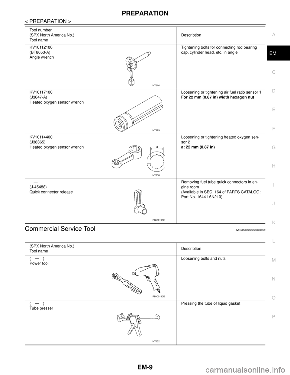
Commercial Service ToolINFOID:0000000003802235
KV10112100
(BT8653-A)
Angle wrenchTightening bolts for connecting rod bearing
cap, cylinder head, etc. in angle
KV10117100
(J3647-A)
Heated oxygen sensor wrenchLoosening or tightening air fuel ratio sensor 1
For 22 mm (0.87 in) width hexagon nut
KV10114400
(J38365)
Heated oxygen sensor wrenchLoosening or tightening heated oxygen sen-
sor 2
a: 22 mm (0.87 in)
—
(J-45488)
Quick connector releaseRemoving fuel tube quick connectors in en-
gine room
(Available in SEC. 164 of PARTS CATALOG:
Part No. 16441 6N210) Tool number
(SPX North America No.)
Tool nameDescription
NT014
NT379
NT636
PBIC0198E
(SPX North America No.)
Tool nameDescription
(—)
Power toolLoosening bolts and nuts
(—)
Tube presserPressing the tube of liquid gasket
PBIC0190E
NT052
Page 1919 of 5121

EM-44
< ON-VEHICLE REPAIR >
FUEL INJECTOR AND FUEL TUBE
FUEL INJECTOR AND FUEL TUBE
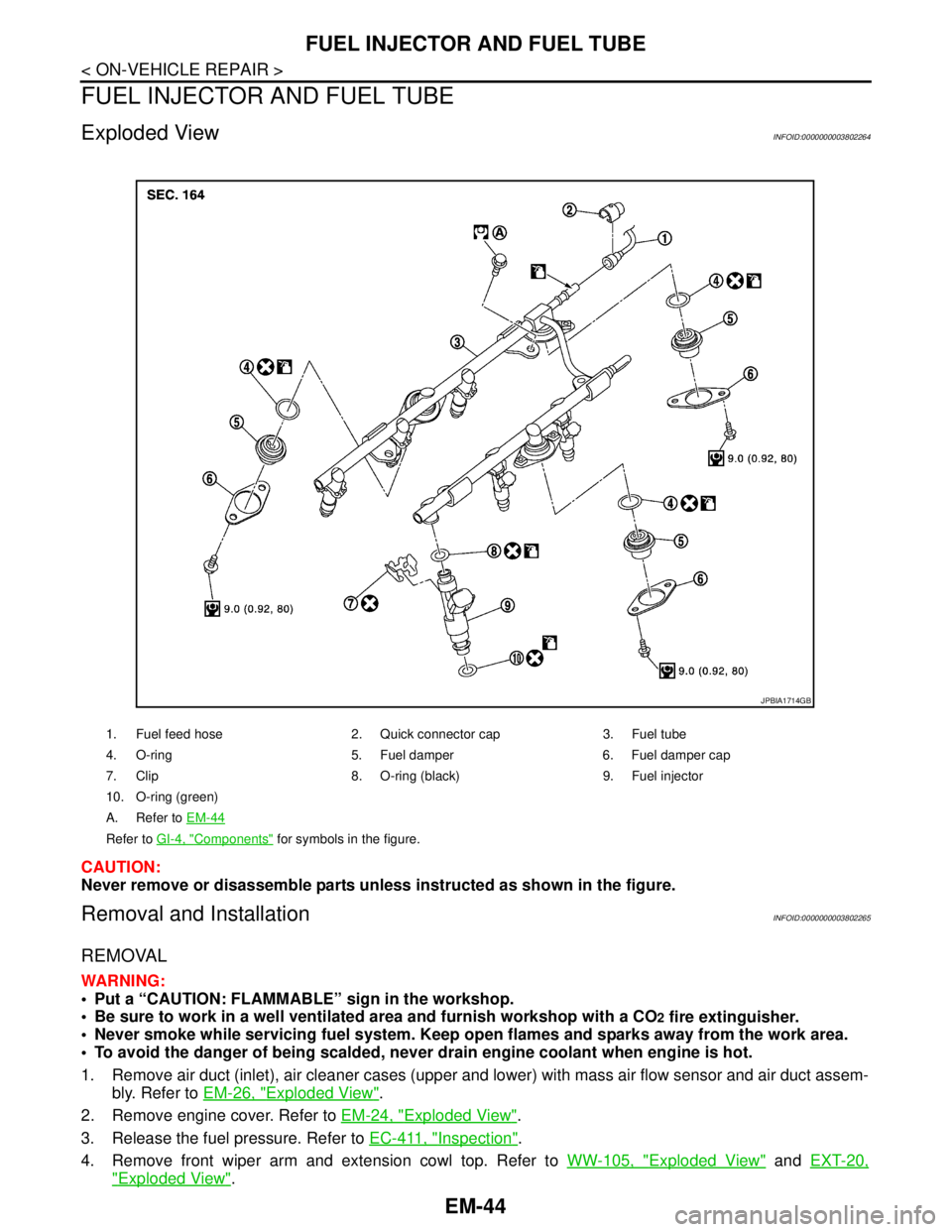
Exploded ViewINFOID:0000000003802264
CAUTION:
Never remove or disassemble parts unless instructed as shown in the figure.
Removal and InstallationINFOID:0000000003802265
REMOVAL
WARNING:
Put a “CAUTION: FLAMMABLE” sign in the workshop.
Be sure to work in a well ventilated area and furnish workshop with a CO
2 fire extinguisher.
Never smoke while servicing fuel system. Keep open flames and sparks away from the work area.
To avoid the danger of being scalded, never drain engine coolant when engine is hot.
1. Remove air duct (inlet), air cleaner cases (upper and lower) with mass air flow sensor and air duct assem-
bly. Refer to EM-26, "
Exploded View".
2. Remove engine cover. Refer to EM-24, "
Exploded View".
3. Release the fuel pressure. Refer to EC-411, "
Inspection".
4. Remove front wiper arm and extension cowl top. Refer to WW-105, "
Exploded View" and EXT-20,
"Exploded View".
1. Fuel feed hose 2. Quick connector cap 3. Fuel tube
4. O-ring 5. Fuel damper 6. Fuel damper cap
7. Clip 8. O-ring (black) 9. Fuel injector
10. O-ring (green)
A. Refer to EM-44
Refer to GI-4, "Components" for symbols in the figure.
JPBIA1714GB
Page 1920 of 5121

FUEL INJECTOR AND FUEL TUBE
EM-45
< ON-VEHICLE REPAIR >
C
D
E
F
G
H
I
J
K
L
MA
EM
N
P O
5. Drain engine coolant, or when water hoses are disconnected, attach plug to prevent engine coolant leak-
age. Refer to CO-8, "
Draining" or EM-28, "Exploded View".
CAUTION:
Perform this step when the engine is cold.
6. Remove intake manifold collector. Refer to EM-28, "
Exploded View".
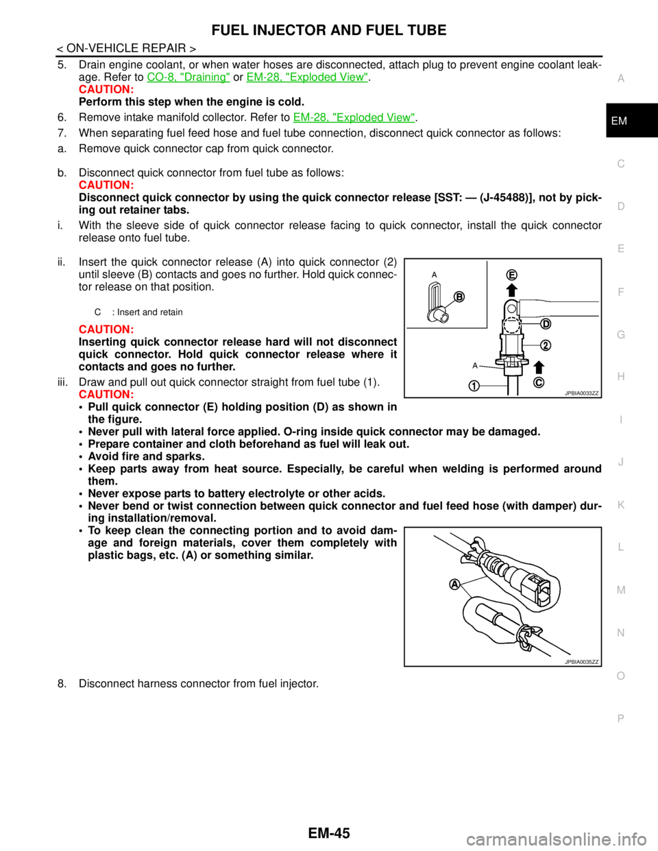
7. When separating fuel feed hose and fuel tube connection, disconnect quick connector as follows:
a. Remove quick connector cap from quick connector.
b. Disconnect quick connector from fuel tube as follows:
CAUTION:
Disconnect quick connector by using the quick connector release [SST: — (J-45488)], not by pick-
ing out retainer tabs.
i. With the sleeve side of quick connector release facing to quick connector, install the quick connector
release onto fuel tube.
ii. Insert the quick connector release (A) into quick connector (2)
until sleeve (B) contacts and goes no further. Hold quick connec-
tor release on that position.
CAUTION:
Inserting quick connector release hard will not disconnect
quick connector. Hold quick connector release where it
contacts and goes no further.
iii. Draw and pull out quick connector straight from fuel tube (1).
CAUTION:
Pull quick connector (E) holding position (D) as shown in
the figure.
Never pull with lateral force applied. O-ring inside quick connector may be damaged.
Prepare container and cloth beforehand as fuel will leak out.
Avoid fire and sparks.
Keep parts away from heat source. Especially, be careful when welding is performed around
them.
Never expose parts to battery electrolyte or other acids.
Never bend or twist connection between quick connector and fuel feed hose (with damper) dur-
ing installation/removal.
To keep clean the connecting portion and to avoid dam-
age and foreign materials, cover them completely with
plastic bags, etc. (A) or something similar.
8. Disconnect harness connector from fuel injector.
C : Insert and retain
JPBIA0033ZZ
JPBIA0035ZZ
Page 2465 of 5121

FL-2
< PRECAUTION >
PRECAUTIONS
PRECAUTION
PRECAUTIONS
General PrecautionsINFOID:0000000003793245
WARNING:
When replacing fuel line parts, be sure to observe the following.
• Put a “CAUTION: FLAMMABLE” sign in the workshop.
Be sure to work in a well ventilated area and furnish workshop with a CO
2 fire extinguisher.
Never smoke while servicing fuel system. Keep open flames and sparks away from the work area.
CAUTION:
Use gasoline required by the regulations for octane number. Refer to GI-29, "
Fuel".
Before removing fuel line parts, perform out the following procedures:
- Put drained fuel in an explosion-proof container and put the lid on securely. Keep the container in
safe area.
- Release fuel pressure from the fuel lines. Refer to EC-411, "
Inspection".
- Disconnect the battery cable from the negative terminal.
Always replace O-ring and clamps with new ones.
Never kink or twist tubes when they are being installed.
Never tighten hose clamps excessively to avoid damaging hoses.
After installing tubes, check there is no fuel leakage at connections in the following steps.
- Apply fuel pressure to fuel lines with turning ignition switch “ON” (with engine stopped). Then check
for fuel leakage at connections.
- Start engine and rev it up and check for fuel leakage at connections.
Use only a genuine NISSAN fuel filler cap as a replacement. If an incorrect fuel filler cap is used, the
“MI” may come on.
For servicing “Evaporative Emission System” parts, refer to EC-76, "
System Diagram".
Page 2469 of 5121

FL-6
< ON-VEHICLE REPAIR >
FUEL LEVEL SENSOR UNIT, FUEL FILTER AND FUEL PUMP ASSEMBLY
b. Disconnect fuel filler hose from fuel filler tube. Refer to FL-9, "Exploded View".
c. Insert hose into fuel tank through fuel filler hose to draw fuel from fuel tank.
2. Release the fuel pressure from the fuel lines. Refer to EC-411, "
Inspection".
3. Open fuel filler lid.
4. Open filler cap and release the pressure inside fuel tank.
5. Remove rear seat cushion. Refer to SE-98, "
Exploded View" (WITH VENTILATION SEAT) or SE-140,
"Exploded View" (WITHOUT VENTILATION SEAT).
6. Peel off floor carpet, then remove inspection hole cover units by
turning clips clockwise by 90 degrees.
7. Disconnect harness connector and quick connector.
Disconnect quick connector as follows:
Hold the sides of connector, push in tabs (B) and pull out fuel
feed tube.
If quick connector sticks to tube of fuel level sensor unit, push
and pull quick connector several times until they start to move.
Then disconnect them by pulling.
CAUTION:
PBIC2520E
PBIC2521E
A: Pull
JPBIA0134ZZ