2008 NISSAN TEANA maintenance
[x] Cancel search: maintenancePage 1099 of 5121

CHG
CHG-1
ELECTRICAL & POWER CONTROL
C
DE
F
G H
I
J
K L
B
SECTION CHG
A
O P
N
CONTENTS
CHARGING SYSTEM
BASIC INSPECTION .......
.............................2
DIAGNOSIS AND REPAIR WORKFLOW ..... .....2
Work Flow ........................................................... ......2
FUNCTION DIAGNOSIS ...............................5
CHARGING SYSTEM ..................................... .....5
System Diagram .................................................. ......5
System Description ...................................................5
Component Parts Location ........................................5
Component Description ............................................5
POWER GENERATION VOLTAGE VARI-
ABLE CONTROL SYSTEM ............................ .....
7
System Diagram .................................................. ......7
System Description ...................................................7
Component Parts Location ........................................7
Component Description .............................................8
COMPONENT DIAGNOSIS ..........................9
B TERMINAL CIRCUIT .................................. .....9
Description .......................................................... ......9
Diagnosis Procedure .................................................9
L TERMINAL CIRCUIT (OPEN) .........................10
Description .......................................................... ....10
Diagnosis Procedure ...............................................10
L TERMINAL CIRCUIT (SHORT) .......................12
Description .......................................................... ....12
Diagnosis Procedure ...............................................12
S TERMINAL CIRCUIT ......................................13
Description .......................................................... ....13
Diagnosis Procedure ...............................................13
CHARGING SYSTEM ..................................... ....14
Wiring Diagram - CHARGING SYSTEM - ........... ....14
SYMPTOM DIAGNOSIS ..............................17
CHARGING SYSTEM .......................................17
Symptom Table ................................................... ....17
PRECAUTION ..............................................18
PRECAUTIONS .................................................18
Precaution for Supplemental Restraint System
(SRS) "AIR BAG" and "SEAT BELT PRE-TEN-
SIONER" ............................................................. ....
18
PREPARATION ...........................................19
PREPARATION .................................................19
Special Service Tools .......................................... ....19
ON-VEHICLE MAINTENANCE ....................20
CHARGING SYSTEM PRELIMINARY IN-
SPECTION ....... ................................ .................
20
Inspection Procedure ........................................... ....20
ON-VEHICLE REPAIR .................................21
ALTERNATOR . ................................ .................21
Exploded View ..................................................... ....21
Removal and Installation .........................................22
Disassembly and Assembly .....................................23
Inspection ................................................................24
SERVICE DATA AND SPECIFICATIONS
(SDS) ............... .............................................
25
SERVICE DATA AND SPECIFICATIONS
(SDS) .................................................................
25
Alternator ............................................................. ....25
Page 1116 of 5121

CHG-18
< PRECAUTION >
PRECAUTIONS
PRECAUTION
PRECAUTIONS
Precaution for Supplemental Restraint System (SRS) "AIR BAG" and "SEAT BELT
PRE-TENSIONER"
INFOID:0000000003860531
The Supplemental Restraint System such as “AIR BAG” and “SEAT BELT PRE-TENSIONER”, used along
with a front seat belt, helps to reduce the risk or severity of injury to the driver and front passenger for certain
types of collision. Information necessary to service the system safely is included in the “SRS AIRBAG” and
“SEAT BELT” of this Service Manual.
WARNING:
• To avoid rendering the SRS inoperative, which could increase the risk of personal injury or death in
the event of a collision which would result in air bag inflation, all maintenance must be performed by
an authorized NISSAN/INFINITI dealer.
Improper maintenance, including incorrect removal and installation of the SRS, can lead to personal
injury caused by unintentional activation of the system. For removal of Spiral Cable and Air Bag
Module, see the “SRS AIRBAG”.
Never use electrical test equipment on any circuit related to the SRS unless instructed to in this Ser-
vice Manual. SRS wiring harnesses can be identified by yellow and/or orange harnesses or harness
connectors.
Page 1118 of 5121
CHG-20
< ON-VEHICLE MAINTENANCE >
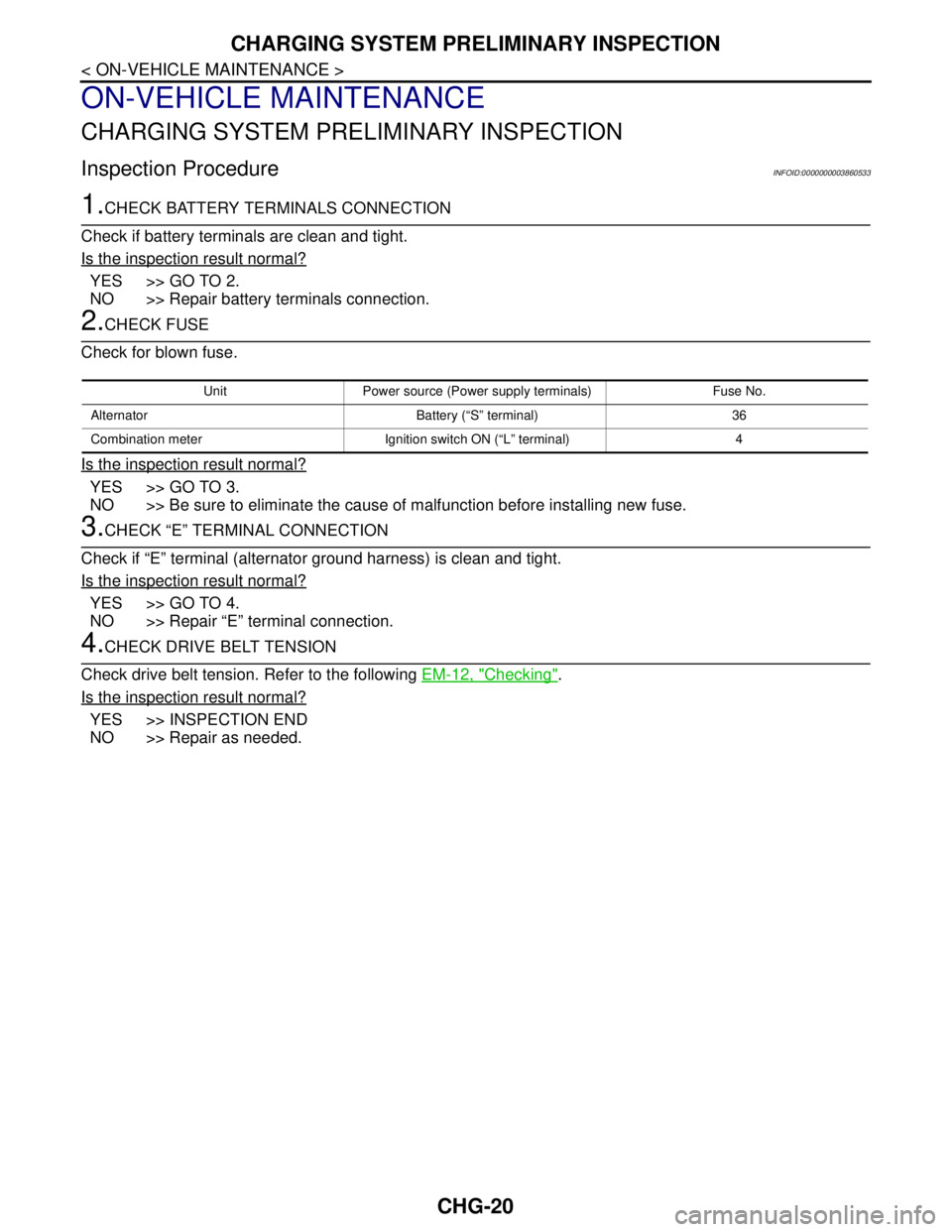
CHARGING SYSTEM PRELIMINARY INSPECTION
ON-VEHICLE MAINTENANCE
CHARGING SYSTEM PRELIMINARY INSPECTION
Inspection ProcedureINFOID:0000000003860533
1.CHECK BATTERY TERMINALS CONNECTION
Check if battery terminals are clean and tight.
Is the inspection result normal?
YES >> GO TO 2.
NO >> Repair battery terminals connection.
2.CHECK FUSE
Check for blown fuse.
Is the inspection result normal?
YES >> GO TO 3.
NO >> Be sure to eliminate the cause of malfunction before installing new fuse.
3.CHECK “E” TERMINAL CONNECTION
Check if “E” terminal (alternator ground harness) is clean and tight.
Is the inspection result normal?
YES >> GO TO 4.
NO >> Repair “E” terminal connection.
4.CHECK DRIVE BELT TENSION
Check drive belt tension. Refer to the following EM-12, "
Checking".
Is the inspection result normal?
YES >> INSPECTION END
NO >> Repair as needed.
Unit Power source (Power supply terminals) Fuse No.
Alternator Battery (“S” terminal) 36
Combination meter Ignition switch ON (“L” terminal) 4
Page 1124 of 5121

CO-1
ENGINE
C
DE
F
G H
I
J
K L
M
SECTION CO
A
CO
N
O P
CONTENTS
ENGINE COOLING SYSTEM
FUNCTION DIAGNOSIS .. .............................2
DESCRIPTION ............................................... .....2
Engine Cooling System ..................................... ......2
Engine Cooling System Schematic .........................2
SYMPTOM DIAGNOSIS ...............................3
OVERHEATING CAUSE ANALYSIS ............. .....3
Troubleshooting Chart ........................................ ......3
PRECAUTION ...............................................5
PRECAUTIONS .............................................. .....5
Precaution for Supplemental Restraint System
(SRS) "AIR BAG" and "SEAT BELT PRE-TEN-
SIONER" ............................................................. ......
5
Liquid Gasket ...........................................................5
PREPARATION ............................................7
PREPARATION .............................................. .....7
Special Service Tool ........................................... ......7
Commercial Service Tools .......................................7
ON-VEHICLE MAINTENANCE .....................8
ENGINE COOLANT ....................................... .....8
Inspection ............................................................ ......8
Draining .....................................................................8
Refilling .....................................................................9
Flushing ...................................................................10
RADIATOR .........................................................12
RADIATOR CAP .................................................... ....12
RADIATOR CAP : Inspection ..................................12
RADIATOR ............................................................ ....12
RADIATOR : Inspection ..........................................12
ON-VEHICLE REPAIR .................................13
RADIATOR ....... ................................ .................13
Exploded View ..................................................... ....13
Removal and Installation .........................................13
Inspection ................................................................15
COOLING FAN ..................................................16
Exploded View .........................................................16
Removal and Installation .........................................16
Disassembly and Assembly .....................................17
Inspection ................................................................17
WATER PUMP ..................................................18
Exploded View .........................................................18
Removal and Installation .........................................18
Inspection ................................................................21
WATER INLET AND THERMOSTAT ASSEM-
BLY ....................................................................
23
Exploded View .........................................................23
Removal and Installation .........................................23
Inspection ................................................................24
WATER OUTLET AND WATER PIPING ..........25
Exploded View .........................................................25
Removal and Installation .........................................25
Inspection ................................................................26
SERVICE DATA AND SPECIFICATIONS
(SDS) ............... .............................................
27
SERVICE DATA AND SPECIFICATIONS
(SDS) .................................................................
27
Periodical Maintenance Specification .................. ....27
Radiator ...................................................................27
Thermostat ..............................................................27
Page 1128 of 5121
PRECAUTIONS
CO-5
< PRECAUTION >
C
D
E
F
G
H
I
J
K
L
MA
CO
N
P O
PRECAUTION
PRECAUTIONS
Precaution for Supplemental Restraint System (SRS) "AIR BAG" and "SEAT BELT
PRE-TENSIONER"
INFOID:0000000003801896
The Supplemental Restraint System such as “AIR BAG” and “SEAT BELT PRE-TENSIONER”, used along
with a front seat belt, helps to reduce the risk or severity of injury to the driver and front passenger for certain
types of collision. This system includes seat belt switch inputs and dual stage front air bag modules. The SRS
system uses the seat belt switches to determine the front air bag deployment, and may only deploy one front
air bag, depending on the severity of a collision and whether the front occupants are belted or unbelted.
Information necessary to service the system safely is included in the “SRS AIRBAG” and “SEAT BELT” of this
Service Manual.
WARNING:
• To avoid rendering the SRS inoperative, which could increase the risk of personal injury or death in
the event of a collision which would result in air bag inflation, all maintenance must be performed by
an authorized NISSAN/INFINITI dealer.
Improper maintenance, including incorrect removal and installation of the SRS, can lead to personal
injury caused by unintentional activation of the system. For removal of Spiral Cable and Air Bag
Module, see the “SRS AIRBAG”.
Do not use electrical test equipment on any circuit related to the SRS unless instructed to in this
Service Manual. SRS wiring harnesses can be identified by yellow and/or orange harnesses or har-
ness connectors.
Liquid GasketINFOID:0000000003793163
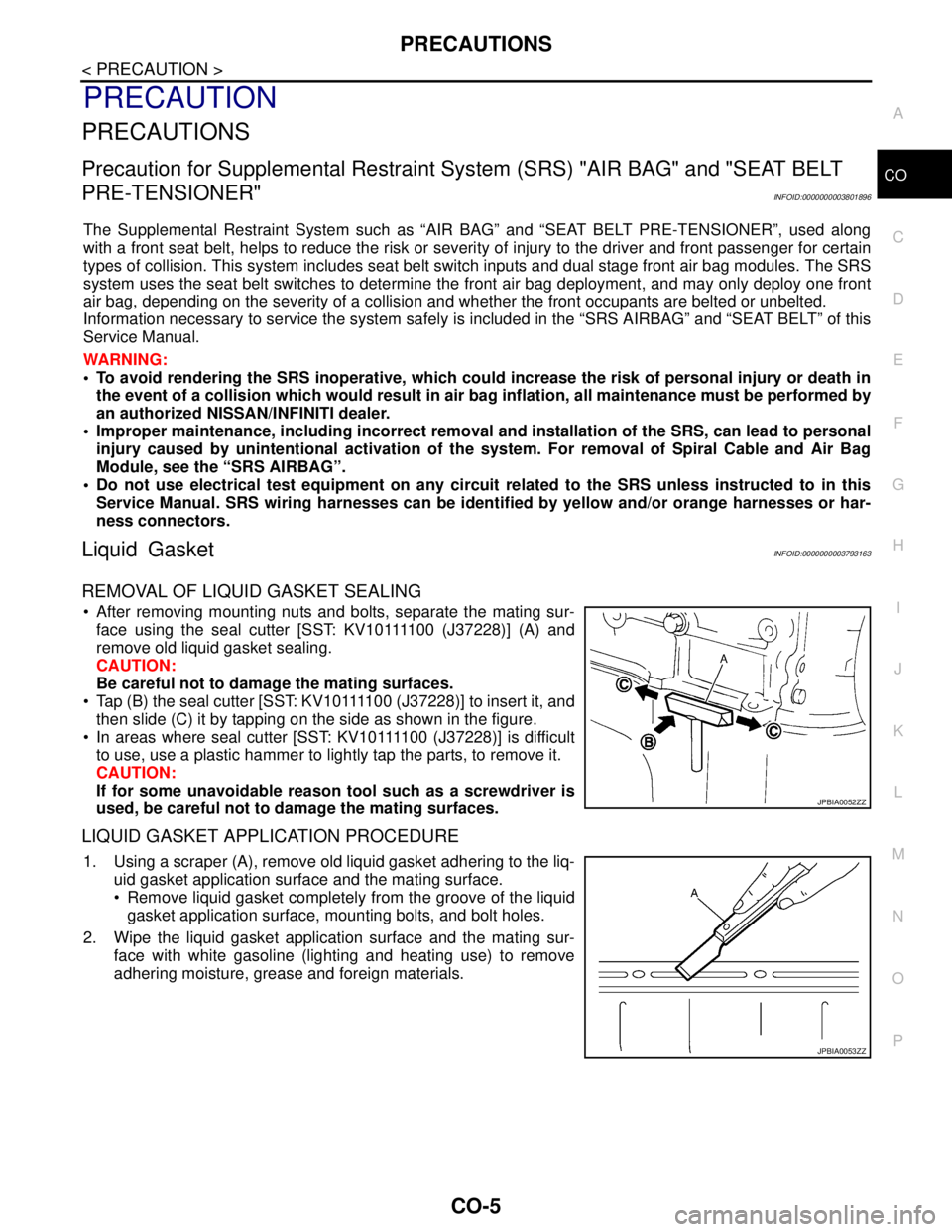
REMOVAL OF LIQUID GASKET SEALING
After removing mounting nuts and bolts, separate the mating sur-
f a c e u s i n g t h e s e a l c u t t e r [ S S T: K V 1 0 1111 0 0 ( J37228)] (A) and
remove old liquid gasket sealing.
CAUTION:
Be careful not to damage the mating surfaces.
Tap (B) the seal cutter [SST: KV10111100 (J37228)] to insert it, and
then slide (C) it by tapping on the side as shown in the figure.
In areas where seal cutter [SST: KV10111100 (J37228)] is difficult
to use, use a plastic hammer to lightly tap the parts, to remove it.
CAUTION:
If for some unavoidable reason tool such as a screwdriver is
used, be careful not to damage the mating surfaces.
LIQUID GASKET APPLICATION PROCEDURE
1. Using a scraper (A), remove old liquid gasket adhering to the liq-
uid gasket application surface and the mating surface.
Remove liquid gasket completely from the groove of the liquid
gasket application surface, mounting bolts, and bolt holes.
2. Wipe the liquid gasket application surface and the mating sur-
face with white gasoline (lighting and heating use) to remove
adhering moisture, grease and foreign materials.
JPBIA0052ZZ
JPBIA0053ZZ
Page 1131 of 5121
CO-8
< ON-VEHICLE MAINTENANCE >
ENGINE COOLANT
ON-VEHICLE MAINTENANCE
ENGINE COOLANT
InspectionINFOID:0000000003793166
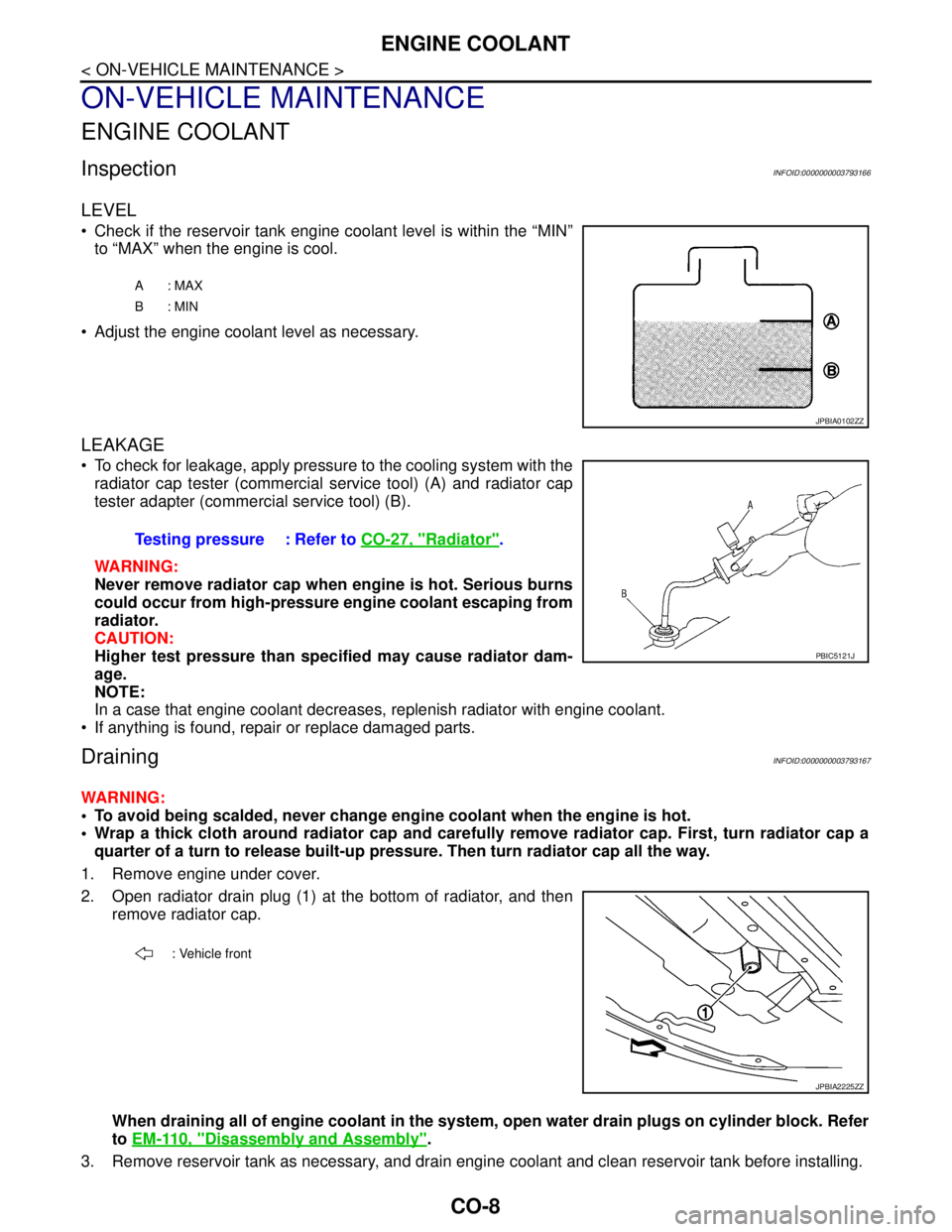
LEVEL
Check if the reservoir tank engine coolant level is within the “MIN”
to “MAX” when the engine is cool.
Adjust the engine coolant level as necessary.
LEAKAGE
To check for leakage, apply pressure to the cooling system with the
radiator cap tester (commercial service tool) (A) and radiator cap
tester adapter (commercial service tool) (B).
WARNING:
Never remove radiator cap when engine is hot. Serious burns
could occur from high-pressure engine coolant escaping from
radiator.
CAUTION:
Higher test pressure than specified may cause radiator dam-
age.
NOTE:
In a case that engine coolant decreases, replenish radiator with engine coolant.
If anything is found, repair or replace damaged parts.
DrainingINFOID:0000000003793167
WARNING:
To avoid being scalded, never change engine coolant when the engine is hot.
Wrap a thick cloth around radiator cap and carefully remove radiator cap. First, turn radiator cap a
quarter of a turn to release built-up pressure. Then turn radiator cap all the way.
1. Remove engine under cover.
2. Open radiator drain plug (1) at the bottom of radiator, and then
remove radiator cap.
When draining all of engine coolant in the system, open water drain plugs on cylinder block. Refer
to EM-110, "
Disassembly and Assembly".
3. Remove reservoir tank as necessary, and drain engine coolant and clean reservoir tank before installing.
A: MAX
B: MIN
JPBIA0102ZZ
Testing pressure : Refer to CO-27, "Radiator".
PBIC5121J
: Vehicle front
JPBIA2225ZZ
Page 1132 of 5121
ENGINE COOLANT
CO-9
< ON-VEHICLE MAINTENANCE >
C
D
E
F
G
H
I
J
K
L
MA
CO
N
P O
4. Check drained engine coolant for contaminants such as rust, corrosion or discoloration.
If contaminated, flush the engine cooling system. Refer to CO-10, "
Flushing".
RefillingINFOID:0000000003793168
1. Install reservoir tank if removed, and radiator drain plug.
CAUTION:
Be sure to clean drain plug and install with new O-ring.
If water drain plugs on cylinder block are removed, close and tighten them. Refer to EM-110, "
Dis-
assembly and Assembly".
2. Check that each hose clamp has been firmly tightened.
3. Remove air duct assembly and air cleaner cases (upper and lower) assembly. Refer to EM-26, "
Exploded
View".
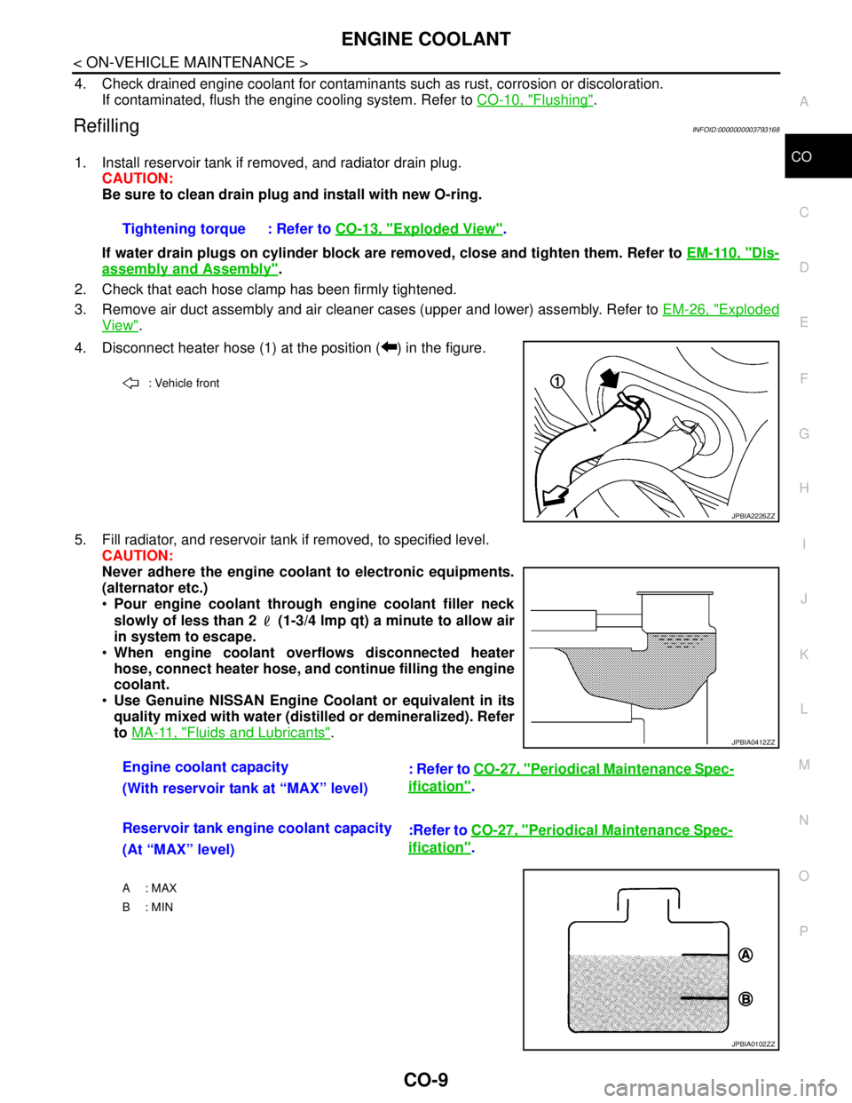
4. Disconnect heater hose (1) at the position ( ) in the figure.
5. Fill radiator, and reservoir tank if removed, to specified level.
CAUTION:
Never adhere the engine coolant to electronic equipments.
(alternator etc.)
Pour engine coolant through engine coolant filler neck
slowly of less than 2 (1-3/4 lmp qt) a minute to allow air
in system to escape.
When engine coolant overflows disconnected heater
hose, connect heater hose, and continue filling the engine
coolant.
Use Genuine NISSAN Engine Coolant or equivalent in its
quality mixed with water (distilled or demineralized). Refer
to MA-11, "
Fluids and Lubricants". Tightening torque : Refer to CO-13, "
Exploded View".
: Vehicle front
JPBIA2226ZZ
Engine coolant capacity
: Refer to CO-27, "Periodical Maintenance Spec-
ification".
(With reservoir tank at “MAX” level)
Reservoir tank engine coolant capacity
:Refer to CO-27, "
Periodical Maintenance Spec-
ification".
(At “MAX” level)
A : MAX
B: MIN
JPBIA0412ZZ
JPBIA0102ZZ
Page 1133 of 5121
CO-10
< ON-VEHICLE MAINTENANCE >
ENGINE COOLANT
6. Install air duct assembly and air cleaner cases (upper and lower) assembly. Refer to EM-26, "Exploded
View".
7. Install radiator cap.
8. Warm up engine until opening thermostat. Standard for warming-up time is approximately 10 minutes at
3,000 rpm.
Check thermostat opening condition by touching radiator hose (lower) to see a flow of warm water.
CAUTION:
Watch water temperature gauge so as not to overheat engine.
9. Stop the engine and cool down to less than approximately 50°C (122°F).
Cool down using fan to reduce the time.
If necessary, refill radiator up to filler neck with engine coolant.
CAUTION:
Never adhere the engine coolant to electronic equipments. (alternator etc.)
10. Refill reservoir tank to “MAX” level line with engine coolant.
11. Repeat steps 7 through 10 two or more times with radiator cap installed until engine coolant level no
longer drops.
12. Check cooling system for leakage with engine running.
13. Warm up the engine, and check for sound of engine coolant flow while running engine from idle up to
3,000 rpm with heater temperature controller set at several position between “COOL” and “WARM”.
Sound may be noticeable at heater unit.
14. Repeat step 13 three times.
15. If sound is heard, bleed air from cooling system by repeating step 5, and steps from 7 to 14 until engine
coolant level no longer drops.
FlushingINFOID:0000000003793169
1. Install reservoir tank if removed, and radiator drain plug.
CAUTION:
Be sure to clean drain plug and install with new O-ring.
If water drain plugs on cylinder block are removed, close and tighten them. Refer to EM-110, "
Dis-
assembly and Assembly".
2. Remove air duct assembly and air cleaner cases (upper and lower) assembly. Refer to EM-26, "
Exploded
View".
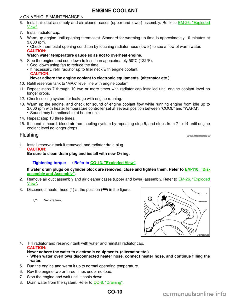
3. Disconnect heater hose (1) at the position ( ) in the figure.
4. Fill radiator and reservoir tank with water and reinstall radiator cap.
CAUTION:
Never adhere the water to electronic equipments. (alternator etc.)
When water overflows disconnected heater hose, connect heater hose, and continue filling the
water.
5. Run the engine and warm it up to normal operating temperature.
6. Rev the engine two or three times under no-load.
7. Stop the engine and wait until it cools down.
8. Drain water from the system. Refer to CO-8, "
Draining". Tightening torque : Refer to CO-13, "
Exploded View".
: Vehicle front
JPBIA2226ZZ