2008 NISSAN TEANA maintenance
[x] Cancel search: maintenancePage 2480 of 5121
FSU-6
< ON-VEHICLE MAINTENANCE >
FRONT SUSPENSION ASSEMBLY
ON-VEHICLE MAINTENANCE
FRONT SUSPENSION ASSEMBLY
InspectionINFOID:0000000003811114
MOUNTING INSPECTION
Make sure the mounting conditions (looseness, backlash) of each component and component conditions
(wear, damage) are normal.
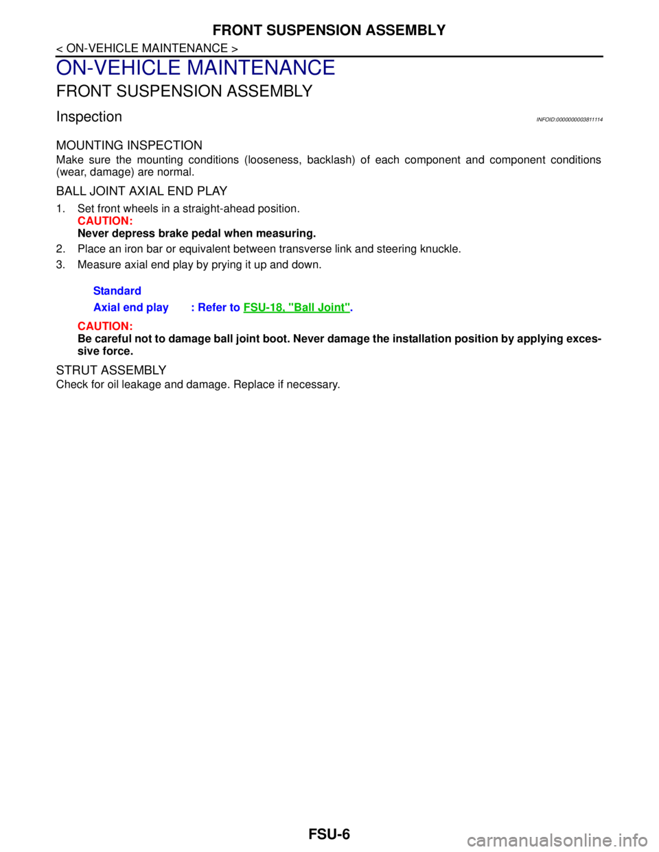
BALL JOINT AXIAL END PLAY
1. Set front wheels in a straight-ahead position.
CAUTION:
Never depress brake pedal when measuring.
2. Place an iron bar or equivalent between transverse link and steering knuckle.
3. Measure axial end play by prying it up and down.
CAUTION:
Be careful not to damage ball joint boot. Never damage the installation position by applying exces-
sive force.
STRUT ASSEMBLY
Check for oil leakage and damage. Replace if necessary.Standard
Axial end play : Refer to FSU-18, "
Ball Joint".
Page 2481 of 5121
WHEEL ALIGNMENT
FSU-7
< ON-VEHICLE MAINTENANCE >
C
D
F
G
H
I
J
K
L
MA
B
FSU
N
O
P
WHEEL ALIGNMENT
Wheel Alignment InspectionINFOID:0000000003812473
INSPECTION
Description
CAUTION:
Camber, caster, kingpin inclination angles cannot be adjusted.
If camber, caster, or kingpin inclination angle exceeds the standard value, check front suspension
parts for wear and damage. Replace suspect parts if a malfunction is detected.
Kingpin inclination angle is reference value, no inspection is required.
Measure wheel alignment under unladen conditions.
NOTE:
“Unladen conditions” means that fuel, engine coolant, and lubricant are full. Spare tire, jack, hand tools and
mats are in designated positions.
Preliminary Check
Check the following:
Tires for improper air pressure and wear
Road wheels for runout: Refer to WT-2, "
Inspection".
Wheel bearing axial end play: Refer to FA X - 6 , "
Inspection".
Transverse link ball joint axial end play: Refer to FSU-11, "
Inspection".
Strut operation.
Each mounting part of axle and suspension for looseness and deformation
Each of suspension member and transverse link for cracks, deformation and other damage
Vehicle height (posture)
CAMBER, CASTER, AND KINGPIN INCLINATION ANGLES
Camber, caster, kingpin inclination angles cannot be adjusted.
Before inspection, mount front wheels onto turning radius gauge. Mount rear wheels onto a stand at the
same height so that vehicle remains horizontal.
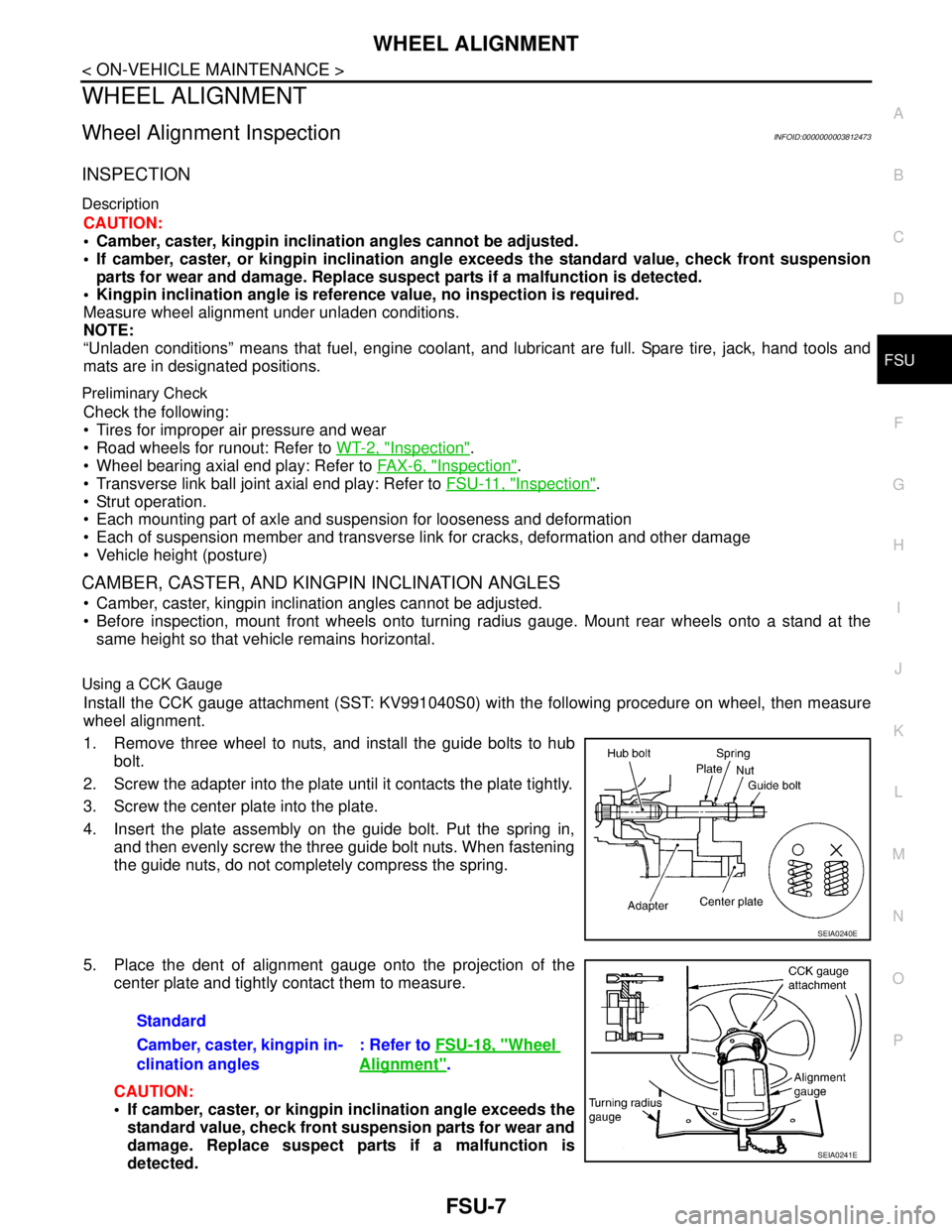
Using a CCK Gauge
Install the CCK gauge attachment (SST: KV991040S0) with the following procedure on wheel, then measure
wheel alignment.
1. Remove three wheel to nuts, and install the guide bolts to hub
bolt.
2. Screw the adapter into the plate until it contacts the plate tightly.
3. Screw the center plate into the plate.
4. Insert the plate assembly on the guide bolt. Put the spring in,
and then evenly screw the three guide bolt nuts. When fastening
the guide nuts, do not completely compress the spring.
5. Place the dent of alignment gauge onto the projection of the
center plate and tightly contact them to measure.
CAUTION:
If camber, caster, or kingpin inclination angle exceeds the
standard value, check front suspension parts for wear and
damage. Replace suspect parts if a malfunction is
detected.
SEIA0240E
Standard
Camber, caster, kingpin in-
clination angles: Refer to FSU-18, "
Wheel
Alignment".
SEIA0241E
Page 2482 of 5121
FSU-8
< ON-VEHICLE MAINTENANCE >
WHEEL ALIGNMENT
Kingpin inclination angle is reference value, no inspection is required.
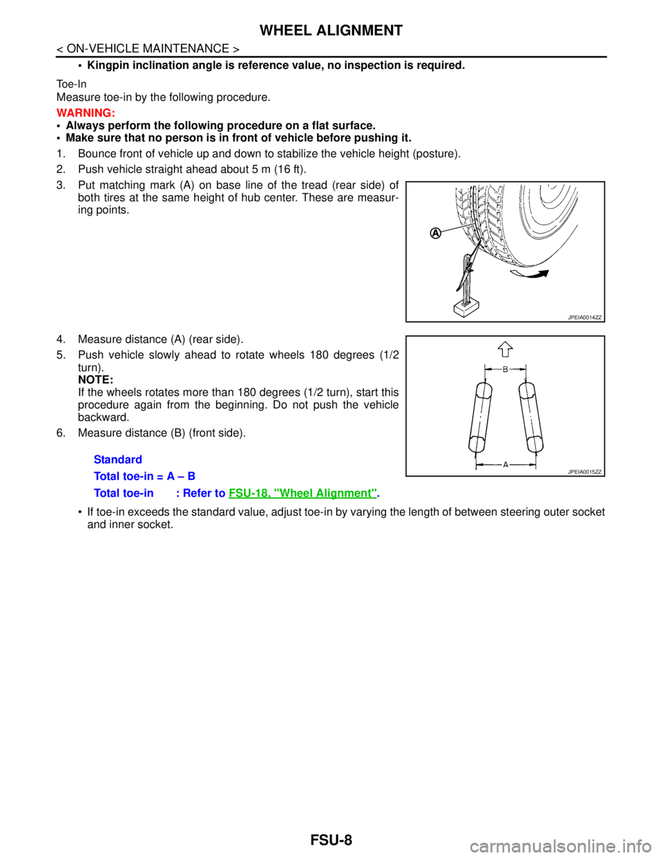
Toe-In
Measure toe-in by the following procedure.
WARNING:
Always perform the following procedure on a flat surface.
Make sure that no person is in front of vehicle before pushing it.
1. Bounce front of vehicle up and down to stabilize the vehicle height (posture).
2. Push vehicle straight ahead about 5 m (16 ft).
3. Put matching mark (A) on base line of the tread (rear side) of
both tires at the same height of hub center. These are measur-
ing points.
4. Measure distance (A) (rear side).
5. Push vehicle slowly ahead to rotate wheels 180 degrees (1/2
turn).
NOTE:
If the wheels rotates more than 180 degrees (1/2 turn), start this
procedure again from the beginning. Do not push the vehicle
backward.
6. Measure distance (B) (front side).
If toe-in exceeds the standard value, adjust toe-in by varying the length of between steering outer socket
and inner socket.
JPEIA0014ZZ
Standard
Total toe-in = A – B
Total toe-in : Refer to FSU-18, "
Wheel Alignment".
JPEIA0015ZZ
Page 2517 of 5121
GI-24
< PRECAUTION >
PRECAUTIONS
PRECAUTION
PRECAUTIONS
DescriptionINFOID:0000000003852776
Observe the following precautions to ensure safe and proper servicing. These precautions are not
described in each individual section.
Precaution for Supplemental Restraint System (SRS) "AIR BAG" and "SEAT BELT
PRE-TENSIONER"
INFOID:0000000003852830
The Supplemental Restraint System such as “AIR BAG” and “SEAT BELT PRE-TENSIONER”, used along
with a front seat belt, helps to reduce the risk or severity of injury to the driver and front passenger for certain
types of collision. Information necessary to service the system safely is included in the “SRS AIRBAG” and
“SEAT BELT” of this Service Manual.
WARNING:
To avoid rendering the SRS inoperative, which could increase the risk of personal injury or death in
the event of a collision which would result in air bag inflation, all maintenance must be performed by
an authorized NISSAN/INFINITI dealer.
Improper maintenance, including incorrect removal and installation of the SRS, can lead to personal
injury caused by unintentional activation of the system. For removal of Spiral Cable and Air Bag
Module, see the “SRS AIRBAG”.
Never use electrical test equipment on any circuit related to the SRS unless instructed to in this Ser-
vice Manual. SRS wiring harnesses can be identified by yellow and/or orange harnesses or harness
connectors.
Precautions For Xenon Headlamp ServiceINFOID:0000000003852778
WARNING:
Comply with the following warnings to prevent any serious accident.
Disconnect the battery cable (negative terminal) or the power supply fuse before installing, remov-
ing, or touching the xenon headlamp (bulb included). The xenon headlamp contains high-voltage
generated parts.
Never work with wet hands.
Check the xenon headlamp ON-OFF status after assembling it to the vehicle. Never turn the xenon
headlamp ON in other conditions. Connect the power supply to the vehicle-side connector.
(Turning it ON outside the lamp case may cause fire or visual impairments.)
Never touch the bulb glass immediately after turning it OFF. It is extremely hot.
CAUTION:
Comply with the following cautions to prevent any error and malfunction.
Install the xenon bulb securely. (Insufficient bulb socket installation may melt the bulb, the connec-
tor, the housing, etc. by high-voltage leakage or corona discharge.)
Never perform HID circuit inspection with a tester.
Never touch the xenon bulb glass with hands. Never put oil and grease on it.
Dispose of the used xenon bulb after packing it in thick vinyl without breaking it.
Never wipe out dirt and contamination with organic solvent (thinner, gasoline, etc.).
Precaution Necessary for Steering Wheel Rotation after Battery Disconnect
INFOID:0000000003852856
NOTE:
Before removing and installing any control units, first turn the push-button ignition switch to the LOCK posi-
tion, then disconnect both battery cables.
After finishing work, confirm that all control unit connectors are connected properly, then re-connect both
battery cables.
Always use CONSULT-III to perform self-diagnosis as a part of each function inspection after finishing work.
If a DTC is detected, perform trouble diagnosis according to self-diagnosis results.
This vehicle is equipped with a push-button ignition switch and a steering lock unit.
If the battery is disconnected or discharged, the steering wheel will lock and cannot be turned.
Page 2551 of 5121
GW-8
< PRECAUTION >
PRECAUTIONS
PRECAUTION
PRECAUTIONS
Precaution for Supplemental Restraint System (SRS) "AIR BAG" and "SEAT BELT
PRE-TENSIONER"
INFOID:0000000003825365
The Supplemental Restraint System such as “AIR BAG” and “SEAT BELT PRE-TENSIONER”, used along
with a front seat belt, helps to reduce the risk or severity of injury to the driver and front passenger for certain
types of collision. Information necessary to service the system safely is included in the “SRS AIRBAG” and
“SEAT BELT” of this Service Manual.
WARNING:
• To avoid rendering the SRS inoperative, which could increase the risk of personal injury or death in
the event of a collision which would result in air bag inflation, all maintenance must be performed by
an authorized NISSAN/INFINITI dealer.
Improper maintenance, including incorrect removal and installation of the SRS, can lead to personal
injury caused by unintentional activation of the system. For removal of Spiral Cable and Air Bag
Module, see the “SRS AIRBAG”.
Never use electrical test equipment on any circuit related to the SRS unless instructed to in this Ser-
vice Manual. SRS wiring harnesses can be identified by yellow and/or orange harnesses or harness
connectors.
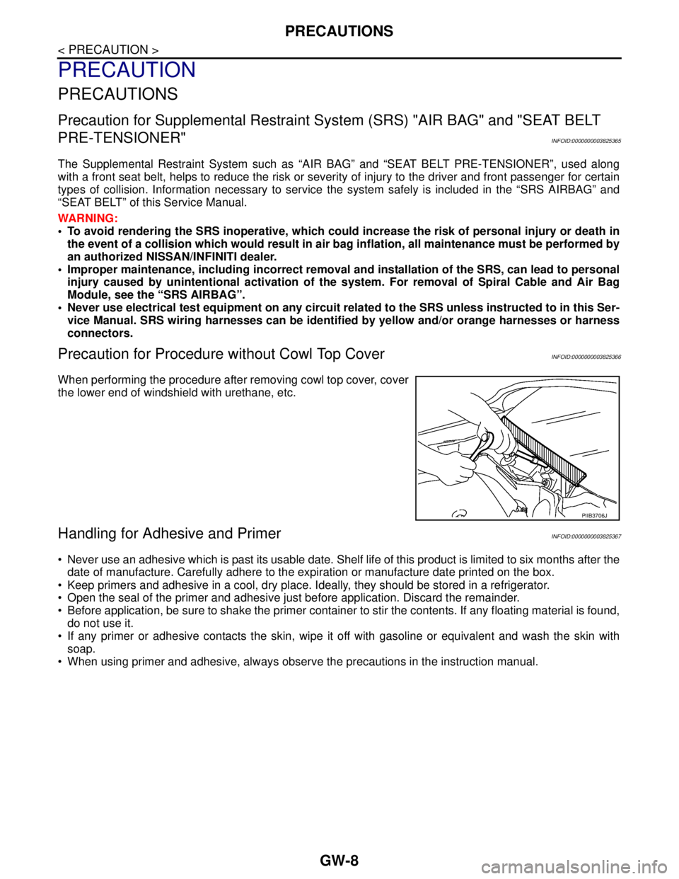
Precaution for Procedure without Cowl Top CoverINFOID:0000000003825366
When performing the procedure after removing cowl top cover, cover
the lower end of windshield with urethane, etc.
Handling for Adhesive and PrimerINFOID:0000000003825367
Never use an adhesive which is past its usable date. Shelf life of this product is limited to six months after the
date of manufacture. Carefully adhere to the expiration or manufacture date printed on the box.
Keep primers and adhesive in a cool, dry place. Ideally, they should be stored in a refrigerator.
Open the seal of the primer and adhesive just before application. Discard the remainder.
Before application, be sure to shake the primer container to stir the contents. If any floating material is found,
do not use it.
If any primer or adhesive contacts the skin, wipe it off with gasoline or equivalent and wash the skin with
soap.
When using primer and adhesive, always observe the precautions in the instruction manual.
PIIB3706J
Page 2570 of 5121

HA-1
VENTILATION, HEATER & AIR CONDITIONER
C
D
E
F
G
H
J
K
L
M
SECTION HA
A
B
HA
N
O
P
CONTENTS
HEATER & AIR CONDITIONING SYSTEM
BASIC INSPECTION ....................................3
DIAGNOSIS AND REPAIR WORK FLOW .........3
Work Flow .................................................................3
FUNCTION DIAGNOSIS ...............................5
REFRIGERATION SYSTEM ...............................5
System Diagram ........................................................5
System Description ...................................................5
Component Parts Location ........................................6
Component Description .............................................7
SYMPTOM DIAGNOSIS ...............................8
REFRIGERATION SYSTEM SYMPTOMS ..........8
Trouble Diagnosis For Unusual Pressure .................8
Symptom Table .........................................................8
COMPRESSOR SYSTEM SYMPTOMS .............11
Symptom Table .......................................................11
PRECAUTION ..............................................12
PRECAUTIONS ..................................................12
Precaution for Supplemental Restraint System
(SRS) "AIR BAG" and "SEAT BELT PRE-TEN-
SIONER" .................................................................
12
Precaution Necessary for Steering Wheel Rota-
tion after Battery Disconnect ...................................
12
Precaution for Procedure without Cowl Top Cover ....13
Precautions For Xenon Headlamp Service .............13
Working with HFC-134a (R-134a) ...........................13
General Refrigerant Precaution ..............................13
Refrigerant Connection ...........................................14
Service Equipment ..................................................16
COMPRESSOR ..................................................19
General Precautions ...............................................19
FLUORESCENT LEAK DETECTOR .................20
General Precautions ...............................................20
PREPARATION ...........................................21
PREPARATION .................................................21
Special Service Tool ................................................21
Sealant or/and Lubricant .........................................23
ON-VEHICLE MAINTENANCE ....................24
REFRIGERANT .................................................24
Collection and Charge .............................................24
LUBRICANT ......................................................28
Maintenance of Lubricant Quantity ..........................28
Lubricant Adjusting Procedure for Components
Replacement Except Compressor ...........................
28
Lubricant Adjusting Procedure for Compressor
Replacement ...........................................................
29
REFRIGERATION SYSTEM .............................30
Inspection ................................................................30
Performance Chart ..................................................30
Refrigerant Leakages ..............................................31
FLUORESCENT LEAK DETECTOR ................32
Inspection ................................................................32
ELECTRICAL LEAK DETECTOR ....................33
Inspection ................................................................33
ON-VEHICLE REPAIR .................................36
COMPRESSOR .................................................36
Exploded View .........................................................36
Removal and Installation .........................................36
Inspection ................................................................37
LOW-PRESSURE FLEXIBLE HOSE ................38
Exploded View .........................................................38
Removal and Installation .........................................38
HIGH-PRESSURE FLEXIBLE HOSE ...............40
Exploded View .........................................................40
Removal and Installation .........................................40
Page 2581 of 5121
HA-12
< PRECAUTION >
PRECAUTIONS
PRECAUTION
PRECAUTIONS
Precaution for Supplemental Restraint System (SRS) "AIR BAG" and "SEAT BELT
PRE-TENSIONER"
INFOID:0000000003844112
The Supplemental Restraint System such as “AIR BAG” and “SEAT BELT PRE-TENSIONER”, used along
with a front seat belt, helps to reduce the risk or severity of injury to the driver and front passenger for certain
types of collision. Information necessary to service the system safely is included in the “SRS AIRBAG” and
“SEAT BELT” of this Service Manual.
WARNING:
• To avoid rendering the SRS inoperative, which could increase the risk of personal injury or death in
the event of a collision which would result in air bag inflation, all maintenance must be performed by
an authorized NISSAN/INFINITI dealer.
Improper maintenance, including incorrect removal and installation of the SRS, can lead to personal
injury caused by unintentional activation of the system. For removal of Spiral Cable and Air Bag
Module, see the “SRS AIRBAG”.
Never use electrical test equipment on any circuit related to the SRS unless instructed to in this Ser-
vice Manual. SRS wiring harnesses can be identified by yellow and/or orange harnesses or harness
connectors.
Precaution Necessary for Steering Wheel Rotation after Battery Disconnect
INFOID:0000000003844113
NOTE:
Before removing and installing any control units, first turn the push-button ignition switch to the LOCK posi-
tion, then disconnect both battery cables.
After finishing work, confirm that all control unit connectors are connected properly, then re-connect both
battery cables.
Always use CONSULT-III to perform self-diagnosis as a part of each function inspection after finishing work.
If a DTC is detected, perform trouble diagnosis according to self-diagnosis results.
This vehicle is equipped with a push-button ignition switch and a steering lock unit.
If the battery is disconnected or discharged, the steering wheel will lock and cannot be turned.
If turning the steering wheel is required with the battery disconnected or discharged, follow the procedure
below before starting the repair operation.
OPERATION PROCEDURE
1. Connect both battery cables.
NOTE:
Supply power using jumper cables if battery is discharged.
2. Turn the push-button ignition switch to ACC position.
(At this time, the steering lock will be released.)
3. Disconnect both battery cables. The steering lock will remain released with both battery cables discon-
nected and the steering wheel can be turned.
4. Perform the necessary repair operation.
5. When the repair work is completed, re-connect both battery cables. With the brake pedal released, turn
the push-button ignition switch from ACC position to ON position, then to LOCK position. (The steering
wheel will lock when the push-button ignition switch is turned to LOCK position.)
6. Perform self-diagnosis check of all control units using CONSULT-III.
Page 2585 of 5121
HA-16
< PRECAUTION >
PRECAUTIONS
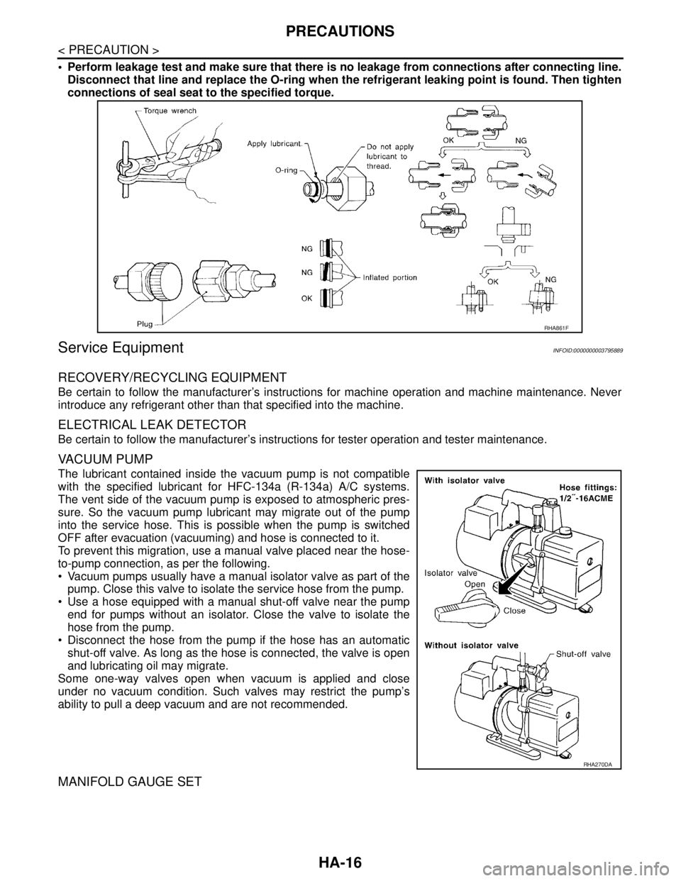
Perform leakage test and make sure that there is no leakage from connections after connecting line.
Disconnect that line and replace the O-ring when the refrigerant leaking point is found. Then tighten
connections of seal seat to the specified torque.
Service EquipmentINFOID:0000000003795889
RECOVERY/RECYCLING EQUIPMENT
Be certain to follow the manufacturer’s instructions for machine operation and machine maintenance. Never
introduce any refrigerant other than that specified into the machine.
ELECTRICAL LEAK DETECTOR
Be certain to follow the manufacturer’s instructions for tester operation and tester maintenance.
VACUUM PUMP
The lubricant contained inside the vacuum pump is not compatible
with the specified lubricant for HFC-134a (R-134a) A/C systems.
The vent side of the vacuum pump is exposed to atmospheric pres-
sure. So the vacuum pump lubricant may migrate out of the pump
into the service hose. This is possible when the pump is switched
OFF after evacuation (vacuuming) and hose is connected to it.
To prevent this migration, use a manual valve placed near the hose-
to-pump connection, as per the following.
Vacuum pumps usually have a manual isolator valve as part of the
pump. Close this valve to isolate the service hose from the pump.
Use a hose equipped with a manual shut-off valve near the pump
end for pumps without an isolator. Close the valve to isolate the
hose from the pump.
Disconnect the hose from the pump if the hose has an automatic
shut-off valve. As long as the hose is connected, the valve is open
and lubricating oil may migrate.
Some one-way valves open when vacuum is applied and close
under no vacuum condition. Such valves may restrict the pump’s
ability to pull a deep vacuum and are not recommended.
MANIFOLD GAUGE SET
RHA861F
RHA270DA