2008 NISSAN TEANA maintenance
[x] Cancel search: maintenancePage 2429 of 5121

FAX-1
TRANSMISSION & DRIVELINE
CEF
G H
I
J
K L
M
SECTION FA X
A
B
FA X
N
O P
CONTENTS
FRONT AXLE
SYMPTOM DIAGNOSIS ..... ..........................2
NOISE, VIBRATION AND HARSHNESS
(NVH) TROUBLESHOOTING ........................ .....
2
NVH Troubleshooting Chart ................................ ......2
PRECAUTION ...............................................3
PRECAUTIONS .............................................. .....3
Precaution for Supplemental Restraint System
(SRS) "AIR BAG" and "SEAT BELT PRE-TEN-
SIONER" ............................................................. ......
3
Precaution Necessary for Steering Wheel Rota-
tion after Battery Disconnect .....................................
3
Precautions for Drive Shaft .......................................3
PREPARATION ............................................5
PREPARATION .............................................. .....5
Special Service Tool ........................................... ......5
ON-VEHICLE MAINTENANCE .....................6
FRONT WHEEL HUB AND KNUCKLE ......... .....6
Inspection ............................................................ ......6
FRONT DRIVE SHAFT ........................................7
Inspection ............................................................ ......7
ON-VEHICLE REPAIR ..................................8
FRONT WHEEL HUB AND KNUCKLE ......... .....8
Exploded View .................................................... ......8
Removal and Installation ...........................................8
Inspection ..................................................................9
FRONT DRIVE SHAFT BOOT ..........................10
Exploded View ..................................................... ....10
WHEEL SIDE ......................................................... ....12
WHEEL SIDE : Removal and Installation ................12
TRANSAXLE SIDE ................................................ ....15
TRANSAXLE SIDE : Removal and Installation .......15
Inspection ............................................................ ....15
FRONT DRIVE SHAFT .....................................16
Exploded View .........................................................16
LEFT SIDE ............................................................. ....18
LEFT SIDE : Removal and Installation ....................18
RIGHT SIDE ........................................................... ....19
RIGHT SIDE : Removal and Installation ..................19
WHEEL SIDE ......................................................... ....20
WHEEL SIDE : Disassembly and Assembly ...........20
TRANSAXLE SIDE ................................................ ....22
TRANSAXLE SIDE : Disassembly and Assembly ....22
Inspection ............................................................ ....33
SERVICE DATA AND SPECIFICATIONS
(SDS) ............... .............................................
35
SERVICE DATA AND SPECIFICATIONS
(SDS) .................................................................
35
Wheel Bearing ..................................................... ....35
Drive Shaft ...............................................................35
Page 2431 of 5121
PRECAUTIONS
FAX-3
< PRECAUTION >
C
E
F
G
H
I
J
K
L
MA
B
FA X
N
O
P
PRECAUTION
PRECAUTIONS
Precaution for Supplemental Restraint System (SRS) "AIR BAG" and "SEAT BELT
PRE-TENSIONER"
INFOID:0000000003890158
The Supplemental Restraint System such as “AIR BAG” and “SEAT BELT PRE-TENSIONER”, used along
with a front seat belt, helps to reduce the risk or severity of injury to the driver and front passenger for certain
types of collision. Information necessary to service the system safely is included in the “SRS AIRBAG” and
“SEAT BELT” of this Service Manual.
WARNING:
• To avoid rendering the SRS inoperative, which could increase the risk of personal injury or death in
the event of a collision which would result in air bag inflation, all maintenance must be performed by
an authorized NISSAN/INFINITI dealer.
Improper maintenance, including incorrect removal and installation of the SRS, can lead to personal
injury caused by unintentional activation of the system. For removal of Spiral Cable and Air Bag
Module, see the “SRS AIRBAG”.
Never use electrical test equipment on any circuit related to the SRS unless instructed to in this Ser-
vice Manual. SRS wiring harnesses can be identified by yellow and/or orange harnesses or harness
connectors.
Precaution Necessary for Steering Wheel Rotation after Battery Disconnect
INFOID:0000000003890159
NOTE:
Before removing and installing any control units, first turn the push-button ignition switch to the LOCK posi-
tion, then disconnect both battery cables.
After finishing work, confirm that all control unit connectors are connected properly, then re-connect both
battery cables.
Always use CONSULT-III to perform self-diagnosis as a part of each function inspection after finishing work.
If a DTC is detected, perform trouble diagnosis according to self-diagnosis results.
This vehicle is equipped with a push-button ignition switch and a steering lock unit.
If the battery is disconnected or discharged, the steering wheel will lock and cannot be turned.
If turning the steering wheel is required with the battery disconnected or discharged, follow the procedure
below before starting the repair operation.
OPERATION PROCEDURE
1. Connect both battery cables.
NOTE:
Supply power using jumper cables if battery is discharged.
2. Turn the push-button ignition switch to ACC position.
(At this time, the steering lock will be released.)
3. Disconnect both battery cables. The steering lock will remain released with both battery cables discon-
nected and the steering wheel can be turned.
4. Perform the necessary repair operation.
5. When the repair work is completed, re-connect both battery cables. With the brake pedal released, turn
the push-button ignition switch from ACC position to ON position, then to LOCK position. (The steering
wheel will lock when the push-button ignition switch is turned to LOCK position.)
6. Perform self-diagnosis check of all control units using CONSULT-III.
Precautions for Drive ShaftINFOID:0000000003811071
CAUTION:
Note the following precautions when disassembling and assembling drive shaft.
Never disassemble joint sub-assembly because it is non-overhaul parts.
Perform work in a dust-free location.
Before disassembling and assembling, clean the parts.
Prevent the entry of foreign objects during disassembly of the service location.
Page 2434 of 5121
FAX-6
< ON-VEHICLE MAINTENANCE >
FRONT WHEEL HUB AND KNUCKLE
ON-VEHICLE MAINTENANCE
FRONT WHEEL HUB AND KNUCKLE
InspectionINFOID:0000000003811074
MOUNTING INSPECTION
Make sure that the mounting conditions (looseness, backlash) of each component and component conditions
(wear, damage) are normal.
WHEEL BEARING INSPECTION
Move wheel hub and bearing assembly in the axial direction by hand. Make sure there is no looseness of
wheel bearing.
Rotate wheel hub and make sure there is no unusual noise or other irregular conditions. If there is any of
irregular conditions, replace wheel hub and bearing assembly.Standard
Axial end play : Refer to FAX-35, "
Wheel Bearing".
Page 2435 of 5121
FRONT DRIVE SHAFT
FAX-7
< ON-VEHICLE MAINTENANCE >
C
E
F
G
H
I
J
K
L
MA
B
FA X
N
O
P
FRONT DRIVE SHAFT
InspectionINFOID:0000000003811075
Check drive shaft mounting point and joint for looseness and other damage.
Check boot for cracks and other damage.
CAUTION:
Replace drive shaft assembly when noise or vibration occur from drive shaft.
Page 2464 of 5121

FL-1
ENGINE
C
DE
F
G H
I
J
K L
M
SECTION FL
A
FL
N
O P
CONTENTS
FUEL SYSTEM
PRECAUTION ................ ...............................2
PRECAUTIONS .............................................. .....2
General Precautions ........................................... ......2
PREPARATION ............................................3
PREPARATION .............................................. .....3
Commercial Service Tool .................................... ......3
ON-VEHICLE MAINTENANCE .....................4
FUEL SYSTEM ............................................... .....4
Inspection ............................................................ ......4
Quick Connector .......................................................4
ON-VEHICLE REPAIR ..................................5
FUEL LEVEL SENSOR UNIT, FUEL FILTER
AND FUEL PUMP ASSEMBLY .........................
5
Exploded View ..................................................... .....5
Removal and Installation ..........................................5
Inspection .................................................................8
FUEL TANK ..................................... ..................9
Exploded View ..................................................... .....9
Removal and Installation ..........................................9
Inspection ................................................................10
SERVICE DATA AND SPECIFICATIONS
(SDS) ............... .............................................
11
SERVICE DATA AND SPECIFICATIONS
(SDS) .................................................................
11
Fuel Tank ............................................................. ....11
Page 2467 of 5121
FL-4
< ON-VEHICLE MAINTENANCE >
FUEL SYSTEM
ON-VEHICLE MAINTENANCE
FUEL SYSTEM
InspectionINFOID:0000000003793248
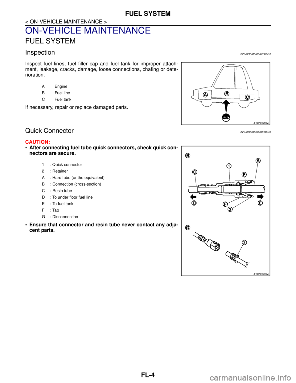
Inspect fuel lines, fuel filler cap and fuel tank for improper attach-
ment, leakage, cracks, damage, loose connections, chafing or dete-
rioration.
If necessary, repair or replace damaged parts.
Quick ConnectorINFOID:0000000003793249
CAUTION:
After connecting fuel tube quick connectors, check quick con-
nectors are secure.
Ensure that connector and resin tube never contact any adja-
cent parts.
A : Engine
B : Fuel line
C: Fuel tank
JPBIA0129ZZ
1 : Quick connector
2: Retainer
A : Hard tube (or the equivalent)
B : Connection (cross-section)
C : Resin tube
D : To under floor fuel line
E : To fuel tank
F: Tab
G : Disconnection
JPBIA0130ZZ
Page 2475 of 5121
FSU-1
SUSPENSION
C
DF
G H
I
J
K L
M
SECTION FSU
A
B
FSU
N
O PCONTENTS
FRONT SUSPENSION
SYMPTOM DIAGNOSIS ..... ..........................2
NOISE, VIBRATION AND HARSHNESS
(NVH) TROUBLESHOOTING ........................ .....
2
NVH Troubleshooting Chart ................................ ......2
PRECAUTION ...............................................3
PRECAUTIONS .............................................. .....3
Precaution for Supplemental Restraint System
(SRS) "AIR BAG" and "SEAT BELT PRE-TEN-
SIONER" ............................................................. ......
3
Precaution Necessary for Steering Wheel Rota-
tion after Battery Disconnect .....................................
3
Precaution for Procedure without Cowl Top Cover ......4
Precautions for Suspension ......................................4
PREPARATION ............................................5
PREPARATION .............................................. .....5
Special Service Tool ........................................... ......5
Commercial Service Tool ..........................................5
ON-VEHICLE MAINTENANCE .....................6
FRONT SUSPENSION ASSEMBLY .............. .....6
Inspection ............................................................ ......6
WHEEL ALIGNMENT ..........................................7
Wheel Alignment Inspection ................................ ......7
ON-VEHICLE REPAIR ..................................9
FRONT COIL SPRING AND STRUT .................9
Exploded View ..................................................... .....9
Removal and Installation ..........................................9
Disassembly and Assembly .....................................10
Inspection ................................................................11
TRANSVERSE LINK .........................................12
Exploded View ..................................................... ....12
Removal and Installation .........................................12
Inspection ................................................................12
FRONT STABILIZER ........................................14
Exploded View .........................................................14
Removal and Installation .........................................14
Inspection ................................................................15
REMOVAL AND INSTALLATION ...............16
FRONT SUSPENSION MEMBER .....................16
Exploded View ..................................................... ....16
Removal and Installation .........................................16
Inspection ................................................................17
SERVICE DATA AND SPECIFICATIONS
(SDS) ............... .............................................
18
SERVICE DATA AND SPECIFICATIONS
(SDS) .................................................................
18
Wheel Alignment ................................................. ....18
Ball Joint ..................................................................18
Wheel Height ...........................................................18
Page 2477 of 5121
PRECAUTIONS
FSU-3
< PRECAUTION >
C
D
F
G
H
I
J
K
L
MA
B
FSU
N
O
P
PRECAUTION
PRECAUTIONS
Precaution for Supplemental Restraint System (SRS) "AIR BAG" and "SEAT BELT
PRE-TENSIONER"
INFOID:0000000003890155
The Supplemental Restraint System such as “AIR BAG” and “SEAT BELT PRE-TENSIONER”, used along
with a front seat belt, helps to reduce the risk or severity of injury to the driver and front passenger for certain
types of collision. Information necessary to service the system safely is included in the “SRS AIRBAG” and
“SEAT BELT” of this Service Manual.
WARNING:
• To avoid rendering the SRS inoperative, which could increase the risk of personal injury or death in
the event of a collision which would result in air bag inflation, all maintenance must be performed by
an authorized NISSAN/INFINITI dealer.
Improper maintenance, including incorrect removal and installation of the SRS, can lead to personal
injury caused by unintentional activation of the system. For removal of Spiral Cable and Air Bag
Module, see the “SRS AIRBAG”.
Never use electrical test equipment on any circuit related to the SRS unless instructed to in this Ser-
vice Manual. SRS wiring harnesses can be identified by yellow and/or orange harnesses or harness
connectors.
Precaution Necessary for Steering Wheel Rotation after Battery Disconnect
INFOID:0000000003890156
NOTE:
Before removing and installing any control units, first turn the push-button ignition switch to the LOCK posi-
tion, then disconnect both battery cables.
After finishing work, confirm that all control unit connectors are connected properly, then re-connect both
battery cables.
Always use CONSULT-III to perform self-diagnosis as a part of each function inspection after finishing work.
If a DTC is detected, perform trouble diagnosis according to self-diagnosis results.
This vehicle is equipped with a push-button ignition switch and a steering lock unit.
If the battery is disconnected or discharged, the steering wheel will lock and cannot be turned.
If turning the steering wheel is required with the battery disconnected or discharged, follow the procedure
below before starting the repair operation.
OPERATION PROCEDURE
1. Connect both battery cables.
NOTE:
Supply power using jumper cables if battery is discharged.
2. Turn the push-button ignition switch to ACC position.
(At this time, the steering lock will be released.)
3. Disconnect both battery cables. The steering lock will remain released with both battery cables discon-
nected and the steering wheel can be turned.
4. Perform the necessary repair operation.
5. When the repair work is completed, re-connect both battery cables. With the brake pedal released, turn
the push-button ignition switch from ACC position to ON position, then to LOCK position. (The steering
wheel will lock when the push-button ignition switch is turned to LOCK position.)
6. Perform self-diagnosis check of all control units using CONSULT-III.