2008 NISSAN TEANA sensor
[x] Cancel search: sensorPage 2472 of 5121

FUEL TANK
FL-9
< ON-VEHICLE REPAIR >
C
D
E
F
G
H
I
J
K
L
MA
FL
N
P O
FUEL TANK
Exploded ViewINFOID:0000000003793254
In regard to the notation of torque in the figure, (A) shows an ISO standard, (B) shows a conventional stan-
dard.
Removal and InstallationINFOID:0000000003793255
WARNING:
Be sure to read “General Precautions” when working on the fuel system. Refer to FL-2, "
General Pre-
cautions".
REMOVAL
Drain fuel from fuel tank if necessary. Refer to FL-5, "Removal and Installation".
Perform work on level place.
1. Perform steps 2 to 7 of “REMOVAL” in “FUEL LEVEL SENSOR UNIT, FUEL FILTER AND FUEL PUMP
ASSEMBLY” on fuel level sensor units. Refer to FL-5, "
Removal and Installation".
2. Remove center muffler. Refer to EX-5, "
Exploded View".
3. Remove fuel tank protector.
1. Clamp 2. Vent hose 3. Clamp
4. EVAP hose 5. Fuel tank 6. Fuel tank mounting band (RH)
7. Clip 8. Fuel tank protector 9. Fuel tank mounting band (LH)
10. Clamp 11. Fuel filler hose 12. Clamp
13. Fuel filler tube 14. Grommet 15. Fuel filler cap
A.The measurement of hexagonal
width across flats: 16 mm (0.63 in)B.The measurement of hexagonal
width across flats: 14 mm (0.55 in)
Refer to GI-4, "
Components" for symbols in the figure.
JPBIA2202GB
Page 2483 of 5121
FRONT COIL SPRING AND STRUT
FSU-9
< ON-VEHICLE REPAIR >
C
D
F
G
H
I
J
K
L
MA
B
FSU
N
O
P
ON-VEHICLE REPAIR
FRONT COIL SPRING AND STRUT
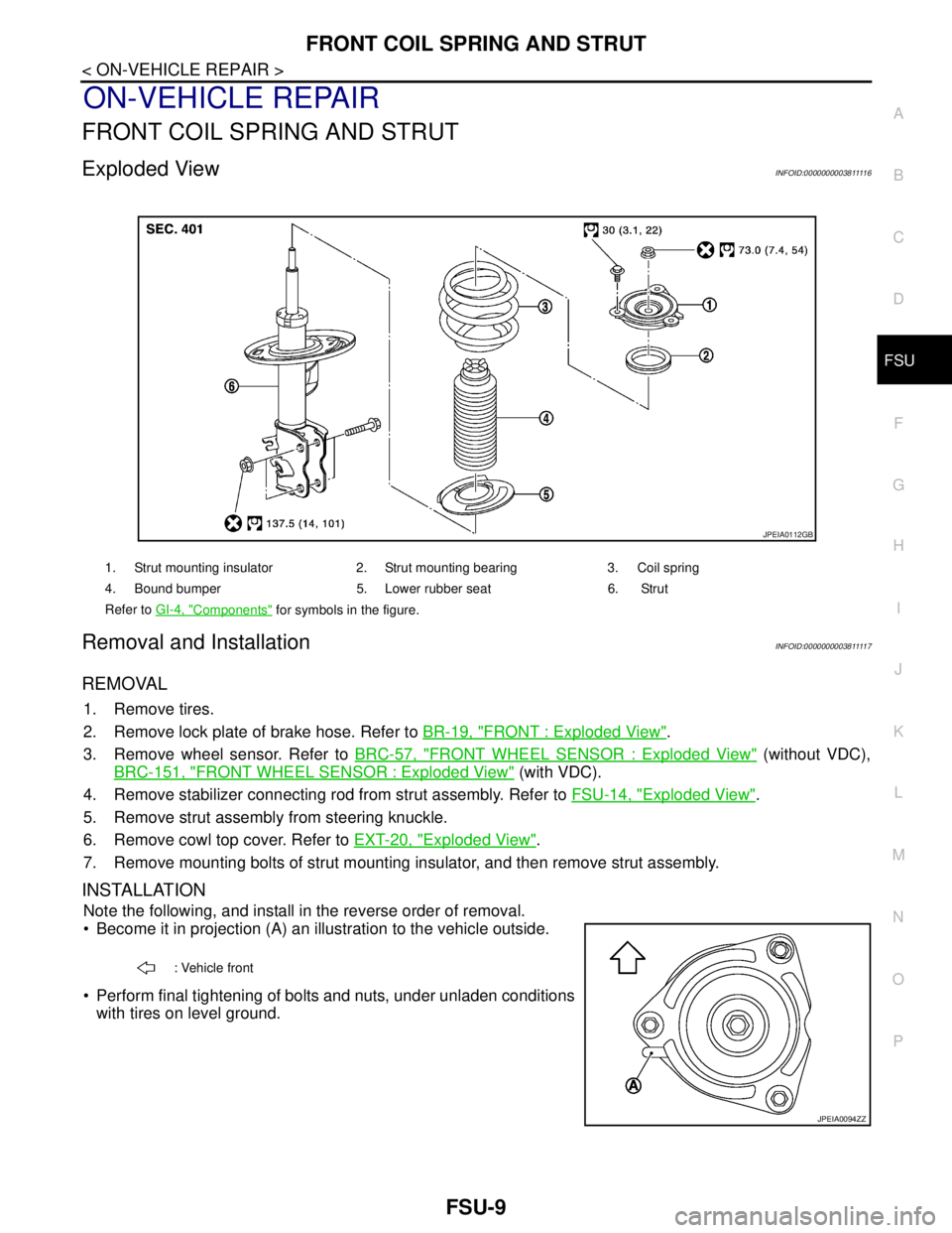
Exploded ViewINFOID:000000000381111 6
Removal and InstallationINFOID:000000000381111 7
REMOVAL
1. Remove tires.
2. Remove lock plate of brake hose. Refer to BR-19, "
FRONT : Exploded View".
3. Remove wheel sensor. Refer to BRC-57, "
FRONT WHEEL SENSOR : Exploded View" (without VDC),
BRC-151, "
FRONT WHEEL SENSOR : Exploded View" (with VDC).
4. Remove stabilizer connecting rod from strut assembly. Refer to FSU-14, "
Exploded View".
5. Remove strut assembly from steering knuckle.
6. Remove cowl top cover. Refer to EXT-20, "
Exploded View".
7. Remove mounting bolts of strut mounting insulator, and then remove strut assembly.
INSTALLATION
Note the following, and install in the reverse order of removal.
Become it in projection (A) an illustration to the vehicle outside.
Perform final tightening of bolts and nuts, under unladen conditions
with tires on level ground.
1. Strut mounting insulator 2. Strut mounting bearing 3. Coil spring
4. Bound bumper 5. Lower rubber seat 6. Strut
Refer to GI-4, "
Components" for symbols in the figure.
JPEIA0112GB
: Vehicle front
JPEIA0094ZZ
Page 2485 of 5121
FRONT COIL SPRING AND STRUT
FSU-11
< ON-VEHICLE REPAIR >
C
D
F
G
H
I
J
K
L
MA
B
FSU
N
O
P
5. Install strut mounting bearing and strut mounting insulator with bound bumper to strut.
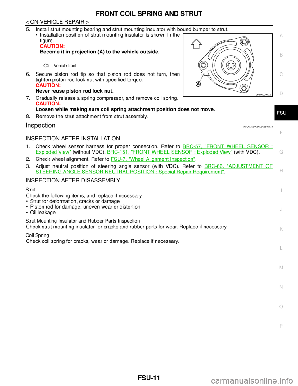
Installation position of strut mounting insulator is shown in the
figure.
CAUTION:
Become it in projection (A) to the vehicle outside.
6. Secure piston rod tip so that piston rod does not turn, then
tighten piston rod lock nut with specified torque.
CAUTION:
Never reuse piston rod lock nut.
7. Gradually release a spring compressor, and remove coil spring.
CAUTION:
Loosen while making sure coil spring attachment position does not move.
8. Remove the strut attachment from strut assembly.
InspectionINFOID:000000000381111 9
INSPECTION AFTER INSTALLATION
1. Check wheel sensor harness for proper connection. Refer to BRC-57, "FRONT WHEEL SENSOR :
Exploded View" (without VDC), BRC-151, "FRONT WHEEL SENSOR : Exploded View" (with VDC).
2. Check wheel alignment. Refer to FSU-7, "
Wheel Alignment Inspection".
3. Adjust neutral position of steering angle sensor (with VDC). Refer to BRC-66, "
ADJUSTMENT OF
STEERING ANGLE SENSOR NEUTRAL POSITION : Special Repair Requirement".
INSPECTION AFTER DISASSEMBLY
Str ut
Check the following items, and replace if necessary.
Strut for deformation, cracks or damage
Piston rod for damage, uneven wear or distortion
Oil leakage
Strut Mounting Insulator and Rubber Parts Inspection
Check strut mounting insulator for cracks and rubber parts for wear. Replace if necessary.
Coil Spring
Check coil spring for cracks, wear or damage. Replace if necessary.
: Vehicle front
JPEIA0094ZZ
Page 2487 of 5121
TRANSVERSE LINK
FSU-13
< ON-VEHICLE REPAIR >
C
D
F
G
H
I
J
K
L
MA
B
FSU
N
O
P
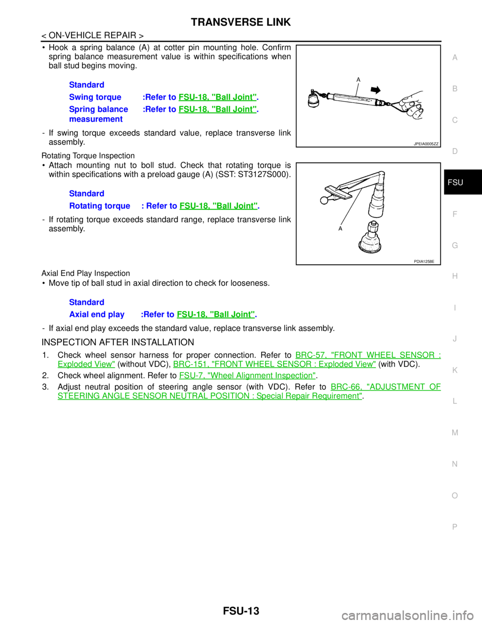
Hook a spring balance (A) at cotter pin mounting hole. Confirm
spring balance measurement value is within specifications when
ball stud begins moving.
- If swing torque exceeds standard value, replace transverse link
assembly.
Rotating Torque Inspection
Attach mounting nut to boll stud. Check that rotating torque is
within specifications with a preload gauge (A) (SST: ST3127S000).
- If rotating torque exceeds standard range, replace transverse link
assembly.
Axial End Play Inspection
Move tip of ball stud in axial direction to check for looseness.
- If axial end play exceeds the standard value, replace transverse link assembly.
INSPECTION AFTER INSTALLATION
1. Check wheel sensor harness for proper connection. Refer to BRC-57, "FRONT WHEEL SENSOR :
Exploded View" (without VDC), BRC-151, "FRONT WHEEL SENSOR : Exploded View" (with VDC).
2. Check wheel alignment. Refer to FSU-7, "
Wheel Alignment Inspection".
3. Adjust neutral position of steering angle sensor (with VDC). Refer to BRC-66, "
ADJUSTMENT OF
STEERING ANGLE SENSOR NEUTRAL POSITION : Special Repair Requirement". Standard
Swing torque :Refer to FSU-18, "
Ball Joint".
Spring balance
measurement:Refer to FSU-18, "
Ball Joint".
JPEIA0005ZZ
Standard
Rotating torque : Refer to FSU-18, "
Ball Joint".
PDIA1258E
Standard
Axial end play :Refer to FSU-18, "
Ball Joint".
Page 2490 of 5121
FSU-16
< REMOVAL AND INSTALLATION >
FRONT SUSPENSION MEMBER
REMOVAL AND INSTALLATION
FRONT SUSPENSION MEMBER
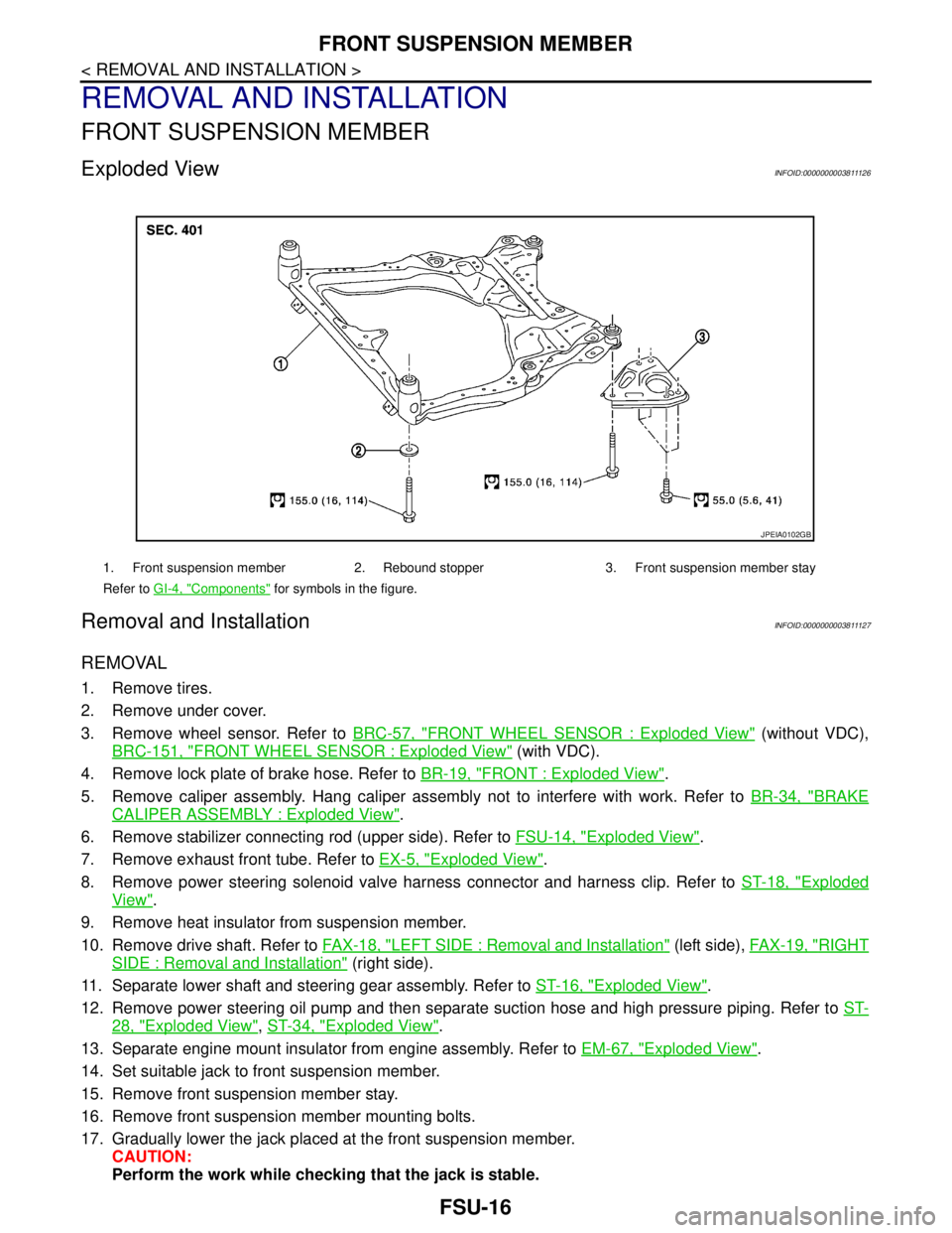
Exploded ViewINFOID:0000000003811126
Removal and InstallationINFOID:0000000003811127
REMOVAL
1. Remove tires.
2. Remove under cover.
3. Remove wheel sensor. Refer to BRC-57, "
FRONT WHEEL SENSOR : Exploded View" (without VDC),
BRC-151, "
FRONT WHEEL SENSOR : Exploded View" (with VDC).
4. Remove lock plate of brake hose. Refer to BR-19, "
FRONT : Exploded View".
5. Remove caliper assembly. Hang caliper assembly not to interfere with work. Refer to BR-34, "
BRAKE
CALIPER ASSEMBLY : Exploded View".
6. Remove stabilizer connecting rod (upper side). Refer to FSU-14, "
Exploded View".
7. Remove exhaust front tube. Refer to EX-5, "
Exploded View".
8. Remove power steering solenoid valve harness connector and harness clip. Refer to ST-18, "
Exploded
View".
9. Remove heat insulator from suspension member.
10. Remove drive shaft. Refer to FAX-18, "
LEFT SIDE : Removal and Installation" (left side), FAX-19, "RIGHT
SIDE : Removal and Installation" (right side).
11. Separate lower shaft and steering gear assembly. Refer to ST-16, "
Exploded View".
12. Remove power steering oil pump and then separate suction hose and high pressure piping. Refer to ST-
28, "Exploded View", ST-34, "Exploded View".
13. Separate engine mount insulator from engine assembly. Refer to EM-67, "
Exploded View".
14. Set suitable jack to front suspension member.
15. Remove front suspension member stay.
16. Remove front suspension member mounting bolts.
17. Gradually lower the jack placed at the front suspension member.
CAUTION:
Perform the work while checking that the jack is stable.
1. Front suspension member 2. Rebound stopper 3. Front suspension member stay
Refer to GI-4, "
Components" for symbols in the figure.
JPEIA0102GB
Page 2491 of 5121
FRONT SUSPENSION MEMBER
FSU-17
< REMOVAL AND INSTALLATION >
C
D
F
G
H
I
J
K
L
MA
B
FSU
N
O
P
NOTE:
Remove the steering knuckle and wheel bearing assembly, steering gear assembly and hydraulic line,
stabilizer bar, transverse link and engine mounting insulator as a unit from the vehicle.
18. Remove the following parts.
Steering knuckle and wheel hub and bearing assembly: refer to FA X - 8 , "
Exploded View".
Steering gear assembly and hydraulic line: refer to ST-18, "
Exploded View" and ST-34, "Exploded
View".
Stabilizer bar: refer to FSU-14, "
Exploded View".
Transverse link: refer to FSU-12, "
Exploded View".
Engine mounting insulator: refer to EM-67, "
Exploded View".
INSTALLATION
Note the following, and install in the reverse order of removal.
Perform final tightening of installation position between front suspension member and transverse links (rub-
ber bushing) under unladen condition with tires on level ground.
InspectionINFOID:0000000003811128
INSPECTION AFTER REMOVAL
Check the front suspension member for significant deformation, cracks, or damages. Replace if necessary.
INSPECTION AFTER INSTALLATION
1. Check wheel sensor harness for proper connection. Refer to BRC-57, "FRONT WHEEL SENSOR :
Exploded View" (without VDC), BRC-151, "FRONT WHEEL SENSOR : Exploded View" (with VDC).
2. Check wheel alignment. Refer to FSU-7, "
Wheel Alignment Inspection".
3. Adjust the neutral position of the steering angle sensor. Refer to BRC-66, "
ADJUSTMENT OF STEERING
ANGLE SENSOR NEUTRAL POSITION : Special Repair Requirement".
Page 2498 of 5121
HOW TO USE THIS MANUAL
GI-5
< HOW TO USE THIS MANUAL >
C
D
E
F
G
H
I
J
K
L
MB
GI
N
O
P
SYMBOLS
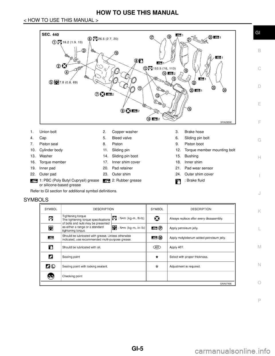
1. Union bolt 2. Copper washer 3. Brake hose
4. Cap 5. Bleed valve 6. Sliding pin bolt
7. Piston seal 8. Piston 9. Piston boot
10. Cylinder body 11. Sliding pin 12. Torque member mounting bolt
13. Washer 14. Sliding pin boot 15. Bushing
16. Torque member 17. Inner shim cover 18. Inner shim
19. Inner pad 20. Pad retainer 21. Pad wear sensor
22. Outer pad 23. Outer shim 24. Outer shim cover
1: PBC (Poly Butyl Cuprysil) grease
or silicone-based grease2: Rubber grease : Brake fluid
Refer to GI section for additional symbol definitions.
SFIA2959E
SAIA0749E
Page 2510 of 5121
TERMINOLOGY
GI-17
< HOW TO USE THIS MANUAL >
C
D
E
F
G
H
I
J
K
L
MB
GI
N
O
PTERMINOLOGY
SAE J1930 Terminology ListINFOID:0000000003852771
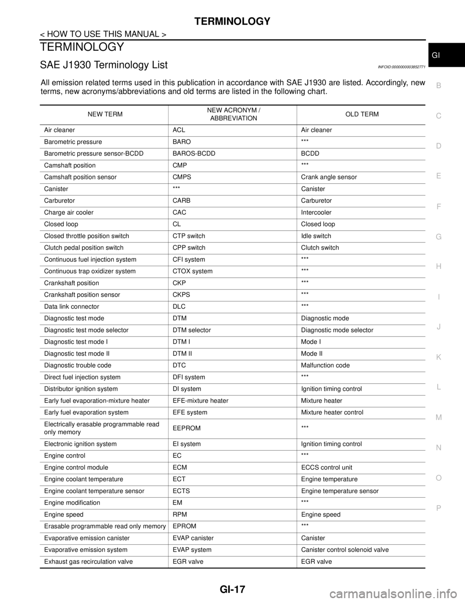
All emission related terms used in this publication in accordance with SAE J1930 are listed. Accordingly, new
terms, new acronyms/abbreviations and old terms are listed in the following chart.
NEW TERMNEW ACRONYM /
ABBREVIATIONOLD TERM
Air cleaner ACL Air cleaner
Barometric pressure BARO ***
Barometric pressure sensor-BCDD BAROS-BCDD BCDD
Camshaft position CMP ***
Camshaft position sensor CMPS Crank angle sensor
Canister *** Canister
Carburetor CARB Carburetor
Charge air cooler CAC Intercooler
Closed loop CL Closed loop
Closed throttle position switch CTP switch Idle switch
Clutch pedal position switch CPP switch Clutch switch
Continuous fuel injection system CFI system ***
Continuous trap oxidizer system CTOX system ***
Crankshaft position CKP ***
Crankshaft position sensor CKPS ***
Data link connector DLC ***
Diagnostic test mode DTM Diagnostic mode
Diagnostic test mode selector DTM selector Diagnostic mode selector
Diagnostic test mode I DTM I Mode I
Diagnostic test mode II DTM II Mode II
Diagnostic trouble code DTC Malfunction code
Direct fuel injection system DFI system ***
Distributor ignition system DI system Ignition timing control
Early fuel evaporation-mixture heater EFE-mixture heater Mixture heater
Early fuel evaporation system EFE system Mixture heater control
Electrically erasable programmable read
only memoryEEPROM ***
Electronic ignition system EI system Ignition timing control
Engine control EC ***
Engine control module ECM ECCS control unit
Engine coolant temperature ECT Engine temperature
Engine coolant temperature sensor ECTS Engine temperature sensor
Engine modification EM ***
Engine speed RPM Engine speed
Erasable programmable read only memory EPROM ***
Evaporative emission canister EVAP canister Canister
Evaporative emission system EVAP system Canister control solenoid valve
Exhaust gas recirculation valve EGR valve EGR valve