2008 NISSAN TEANA sensor
[x] Cancel search: sensorPage 2574 of 5121
REFRIGERATION SYSTEM
HA-5
< FUNCTION DIAGNOSIS >
C
D
E
F
G
H
J
K
L
MA
B
HA
N
O
P
FUNCTION DIAGNOSIS
REFRIGERATION SYSTEM
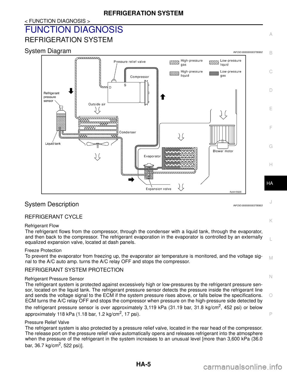
System DiagramINFOID:0000000003795802
System DescriptionINFOID:0000000003795803
REFRIGERANT CYCLE
Refrigerant Flow
The refrigerant flows from the compressor, through the condenser with a liquid tank, through the evaporator,
and then back to the compressor. The refrigerant evaporation in the evaporator is controlled by an externally
equalized expansion valve, located at dash panels.
Freeze Protection
To prevent the evaporator from freezing up, the evaporator air temperature is monitored, and the voltage sig-
nal to the A/C auto amp. turns the A/C relay OFF and stops the compressor.
REFRIGERANT SYSTEM PROTECTION
Refrigerant Pressure Sensor
The refrigerant system is protected against excessively high or low-pressures by the refrigerant pressure sen-
sor, located on the liquid tank. The refrigerant pressure sensor detects the pressure inside the refrigerant line
and sends the voltage signal to the ECM if the system pressure rises above, or falls below the specifications.
ECM turns the A/C relay OFF and stops the compressor when pressure on the high-pressure side detected by
the refrigerant pressure sensor is over approximately 3,119 kPa (31.19 bar, 31.8 kg/cm
2, 452 psi) or below
approximately 118 kPa (1.18 bar, 1.2 kg/cm
2, 17 psi).
Pressure Relief Valve
The refrigerant system is also protected by a pressure relief valve, located in the rear head of the compressor.
The release port on the pressure relief valve automatically opens and releases refrigerant into the atmosphere
when the pressure of the refrigerant in the system increases to an unusual level [more than 3,600 kPa (36.0
bar, 36.7 kg/cm
2, 522 psi)].
RJIA1552E
Page 2575 of 5121
HA-6
< FUNCTION DIAGNOSIS >
REFRIGERATION SYSTEM
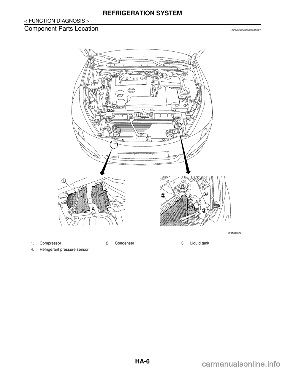
Component Parts Location
INFOID:0000000003795804
1. Compressor 2. Condenser 3. Liquid tank
4. Refrigerant pressure sensor
JPIIA0990ZZ
Page 2576 of 5121
REFRIGERATION SYSTEM
HA-7
< FUNCTION DIAGNOSIS >
C
D
E
F
G
H
J
K
L
MA
B
HA
N
O
P
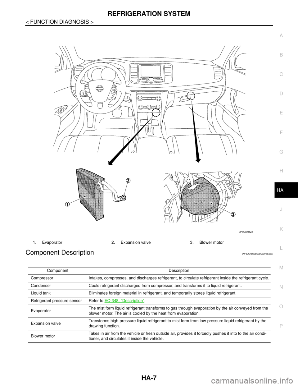
Component DescriptionINFOID:0000000003795805
1. Evaporator 2. Expansion valve 3. Blower motor
JPIIA0991ZZ
Component Description
Compressor Intakes, compresses, and discharges refrigerant, to circulate refrigerant inside the refrigerant cycle.
Condenser Cools refrigerant discharged from compressor, and transforms it to liquid refrigerant.
Liquid tank Eliminates foreign material in refrigerant, and temporarily stores liquid refrigerant.
Refrigerant pressure sensor Refer to EC-348, "
Description".
EvaporatorThe mist form liquid refrigerant transforms to gas through evaporation by the air conveyed from the
blower motor. The air is cooled by the heat from evaporation.
Expansion valveTransforms high-pressure liquid refrigerant to mist form from low-pressure liquid refrigerant by the
drawing function.
Blower motorTakes in air from the vehicle or fresh outside air, provides it forcedly pushes it into to the air condi-
tioner, and circulates it inside the vehicle.
Page 2578 of 5121
REFRIGERATION SYSTEM SYMPTOMS
HA-9
< SYMPTOM DIAGNOSIS >
C
D
E
F
G
H
J
K
L
MA
B
HA
N
O
P
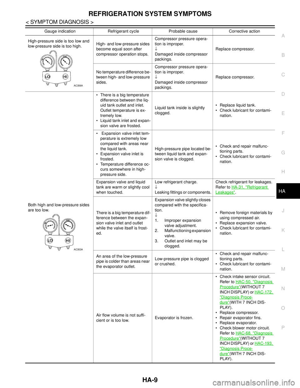
High-pressure side is too low and
low-pressure side is too high.High- and low-pressure sides
become equal soon after
compressor operation stops.Compressor pressure opera-
tion is improper.
↓
Damaged inside compressor
packings.Replace compressor.
No temperature difference be-
tween high- and low-pressure
sides.Compressor pressure opera-
tion is improper.
↓
Damaged inside compressor
packings.Replace compressor.
Both high and low-pressure sides
are too low. There is a big temperature
difference between the liq-
uid tank outlet and inlet.
Outlet temperature is ex-
tremely low.
Liquid tank inlet and expan-
sion valve are frosted.Liquid tank inside is slightly
clogged. Replace liquid tank.
Check lubricant for contami-
nation.
Expansion valve inlet tem-
perature is extremely low
compared with areas near
the liquid tank.
Expansion valve inlet is
frosted.
Temperature difference oc-
curs somewhere in high-
pressure side.High-pressure pipe located be-
tween liquid tank and expan-
sion valve is clogged. Check and repair malfunc-
tioning parts.
Check lubricant for contami-
nation.
Expansion valve and liquid
tank are warm or slightly cool
when touched.Low refrigerant charge.
↓
Leaking fittings or components.Check refrigerant for leakages.
Refer to HA-31, "
Refrigerant
Leakages".
There is a big temperature dif-
ference between the expan-
sion valve inlet and outlet
while the valve itself is frost-
ed.Expansion valve slightly closes
compared with the specifica-
tion.
↓
1. Improper expansion
valve adjustment.
2. Malfunctioning expansion
valve.
3. Outlet and inlet may be
clogged. Remove foreign materials by
using compressed air.
Replace expansion valve.
Check lubricant for contami-
nation.
An area of the low-pressure
pipe is colder than areas near
the evaporator outlet.Low-pressure pipe is clogged
or crushed. Check and repair malfunc-
tioning parts.
Check lubricant for contami-
nation.
Air flow volume is not suffi-
cient or is too low.Evaporator is frozen. Check intake sensor circuit.
Refer to HAC-50, "
Diagnosis
Procedure"(WITHOUT 7
INCH DISPLAY) or HAC-172,
"Diagnosis Proce-
dure"(WITH 7 INCH DIS-
PLAY).
Replace compressor.
Repair evaporator fins.
Replace evaporator.
Check blower motor circuit.
Refer to HAC-68, "
Diagnosis
Procedure"(WITHOUT 7
INCH DISPLAY) or HAC-193,
"Diagnosis Proce-
dure"(WITH 7 INCH DIS-
PLAY). Gauge indication Refrigerant cycle Probable cause Corrective action
AC356A
AC353A
Page 2583 of 5121

HA-14
< PRECAUTION >
PRECAUTIONS
Ventilate work area before resuming service if accidental system discharge occurs. Additional health
and safety information may be obtained from refrigerant and lubricant manufacturers.
Never release refrigerant into the air. Use approved recovery/recycling equipment to capture the
refrigerant each time an air conditioning system is discharged.
Wear always eye and hand protection (goggles and gloves) when working with any refrigerant or air
conditioning system.
Never store or heat refrigerant containers above 52°C (126°F).
Never heat a refrigerant container with an open flame; Place the bottom of the container in a warm
pail of water if container warming is required.
Never intentionally drop, puncture, or incinerate refrigerant containers.
Keep refrigerant away from open flames: poisonous gas is produced if refrigerant burns.
Refrigerant displaces oxygen, therefore be certain to work in well ventilated areas to prevent suffo-
cation.
Never pressure test or leakage test HFC-134a (R-134a) service equipment and/or vehicle air condi-
tioning systems with compressed air during repair. Some mixtures of air and HFC-134a (R-134a)
have been shown to be combustible at elevated pressures. These mixtures, if ignited, may cause
injury or property damage. Additional health and safety information may be obtained from refriger-
ant manufacturers.
Refrigerant ConnectionINFOID:0000000003799207
A new type refrigerant connection has been introduced to all refrigerant lines except the following locations.
Expansion valve to evaporator
Refrigerant pressure sensor to liquid tank
O-RING AND REFRIGERANT CONNECTION
CAUTION:
The new and former refrigerant connections use different O-ring configurations. Never confuse O-
rings since they are not interchangeable. Refrigerant may leak at the connection if a wrong O-ring is
installed.
F. Former type refrigerant connection N. New type refrigerant connection
:O-ring size
JPIIA0986ZZ
Page 2584 of 5121
PRECAUTIONS
HA-15
< PRECAUTION >
C
D
E
F
G
H
J
K
L
MA
B
HA
N
O
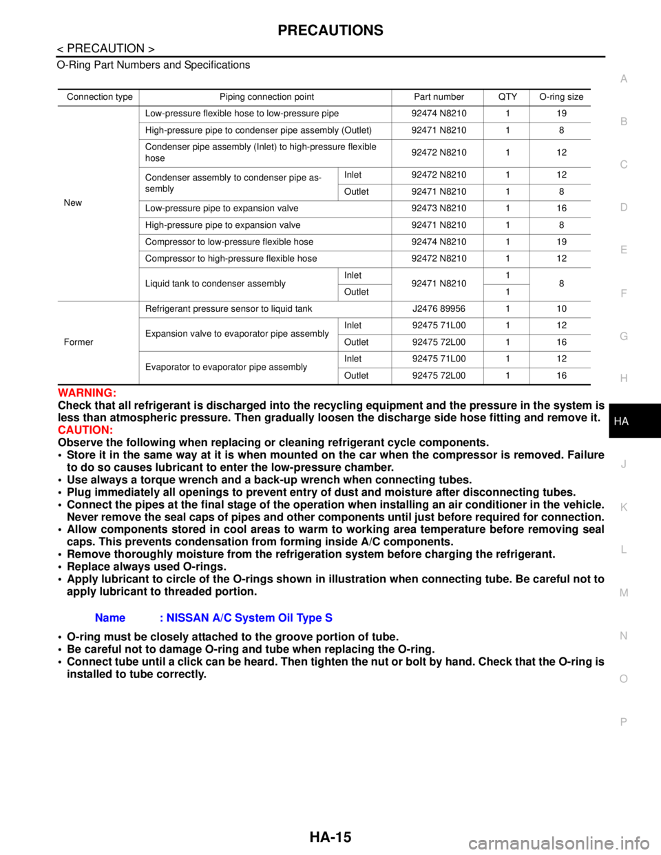
P O-Ring Part Numbers and Specifications
WARNING:
Check that all refrigerant is discharged into the recycling equipment and the pressure in the system is
less than atmospheric pressure. Then gradually loosen the discharge side hose fitting and remove it.
CAUTION:
Observe the following when replacing or cleaning refrigerant cycle components.
Store it in the same way at it is when mounted on the car when the compressor is removed. Failure
to do so causes lubricant to enter the low-pressure chamber.
Use always a torque wrench and a back-up wrench when connecting tubes.
Plug immediately all openings to prevent entry of dust and moisture after disconnecting tubes.
Connect the pipes at the final stage of the operation when installing an air conditioner in the vehicle.
Never remove the seal caps of pipes and other components until just before required for connection.
Allow components stored in cool areas to warm to working area temperature before removing seal
caps. This prevents condensation from forming inside A/C components.
Remove thoroughly moisture from the refrigeration system before charging the refrigerant.
Replace always used O-rings.
Apply lubricant to circle of the O-rings shown in illustration when connecting tube. Be careful not to
apply lubricant to threaded portion.
O-ring must be closely attached to the groove portion of tube.
Be careful not to damage O-ring and tube when replacing the O-ring.
Connect tube until a click can be heard. Then tighten the nut or bolt by hand. Check that the O-ring is
installed to tube correctly.
Connection type Piping connection point Part number QTY O-ring size
NewLow-pressure flexible hose to low-pressure pipe 92474 N8210 1 19
High-pressure pipe to condenser pipe assembly (Outlet) 92471 N8210 1 8
Condenser pipe assembly (Inlet) to high-pressure flexible
hose92472 N8210 1 12
Condenser assembly to condenser pipe as-
semblyInlet 92472 N8210 1 12
Outlet 92471 N8210 1 8
Low-pressure pipe to expansion valve 92473 N8210 1 16
High-pressure pipe to expansion valve 92471 N8210 1 8
Compressor to low-pressure flexible hose 92474 N8210 1 19
Compressor to high-pressure flexible hose 92472 N8210 1 12
Liquid tank to condenser assemblyInlet
92471 N82101
8
Outlet 1
FormerRefrigerant pressure sensor to liquid tank J2476 89956 1 10
Expansion valve to evaporator pipe assemblyInlet 92475 71L00 1 12
Outlet 92475 72L00 1 16
Evaporator to evaporator pipe assemblyInlet 92475 71L00 1 12
Outlet 92475 72L00 1 16
Name : NISSAN A/C System Oil Type S
Page 2601 of 5121

HA-32
< ON-VEHICLE MAINTENANCE >
FLUORESCENT LEAK DETECTOR
FLUORESCENT LEAK DETECTOR
InspectionINFOID:0000000003795981
CHECKING SYSTEM FOR LEAKAGES USING THE FLUORESCENT LEAK DETECTOR
1. Check A/C system for leakages using the UV lamp and safety goggles (SST: J-42220) in a low sunlight
area (area without windows preferable). Illuminate all components, fittings and lines. The dye appears as
a bright green/yellow area at the point of leakage. Fluorescent dye observed at the evaporator drain open-
ing indicates an evaporator core assembly (tubes, core or expansion valve) leakage.
2. Use an adjustable mirror or wipe the area with a clean shop rag or cloth, with the UV lamp for dye residue
if the suspected area is difficult to see.
3. Remove any residual dye using dye cleaner (SST: J-43872) to prevent future misdiagnosis after the leak-
age is repaired.
4. Perform a system performance check and verify the leakage repair with an approved electrical leak detec-
tor.
NOTE:
Other gases in the work area or substances on the A/C components, for example, anti-freeze, windshield
washer fluid, solvents and lubricants, may falsely trigger the leak detector. Make sure the surfaces to be
checked are clean.
Clean with a dry cloth or blow off with shop air.
Do not allow the sensor tip of the detector to contact with any substance. This may also cause false readings
and may damage the detector.
DYE INJECTION
(This procedure is only necessary when recharging the system or when the compressor has seized and was
replaced.)
1. Check A/C system static (at rest) pressure. Pressure must be at least 345 kPa (3.45 bar, 3.52 kg/cm
2, 50
psi).
2. Pour one bottle (1/4 ounce / 7.4 cc) of the A/C refrigerant dye into the injector tool (SST: J-41459).
3. Connect the injector tool to the A/C low-pressure side service valve.
4. Start the engine. Then switch A/C ON.
5. Inject one bottle (1/4 ounce / 7.4 cc) of fluorescent dye through the low-pressure service valve using dye
injector tool (SST: J-41459) (refer to the manufacture’s operating instructions) when the A/C operating
(compressor running).
6. Disconnect the injector tool from the service valve with the engine still running.
CAUTION:
Be careful when replacing the A/C system or a component, pour the dye directly into the open sys-
tem connection and proceed with the service procedures.
7. Operate the A/C system for a minimum of 20 minutes to mix the dye with the system oil. Depending on the
leakage size, operating conditions and location of the leakage, it may take from minutes to days for the
dye to penetrate a leakage and become visible.
8. Attach a blue label if necessary.
Page 2603 of 5121
HA-34
< ON-VEHICLE MAINTENANCE >
ELECTRICAL LEAK DETECTOR
2. Connect a suitable A/C manifold gauge set (SST) to the A/C service valves.
3. Check if the A/C refrigerant pressure is at least 345 kPa (3.45 bar, 3.52 kg/cm
2, 50 psi) above 16°C
(61°F). Recover/evacuate and recharge the system with the specified amount of refrigerant if less than
specification.
NOTE:
Leakages may not be detected since the system may not reach 345 kPa (3.45 bar, 3.52 kg/cm
2, 50 psi) at
temperatures below 16°C (61°F).
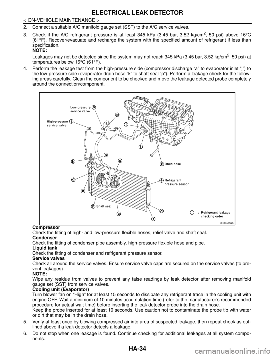
4. Perform the leakage test from the high-pressure side (compressor discharge “a” to evaporator inlet “j”) to
the low-pressure side (evaporator drain hose “k” to shaft seal “p”). Perform a leakage check for the follow-
ing areas carefully. Clean the component to be checked and move the leakage detected probe completely
around the connection/component.
Compressor
Check the fitting of high- and low-pressure flexible hoses, relief valve and shaft seal.
Condenser
Check the fitting of condenser pipe assembly, high-pressure flexible hose and pipe.
Liquid tank
Check the fitting of condenser and refrigerant pressure sensor.
Service valves
Check all around the service valves. Ensure service valve caps are secured on the service valves (to pre-
vent leakages).
NOTE:
Wipe any residue from valves to prevent any false readings by leak detector after removing manifold
gauge set (SST) from service valves.
Cooling unit (Evaporator)
Turn blower fan on “High” for at least 15 seconds to dissipate any refrigerant trace in the cooling unit with
engine OFF. Wait a minimum of 10 minutes accumulation time (refer to the manufacturer’s recommended
procedure for actual wait time) before inserting the leak detector probe into the drain hose.
Keep the probe inserted for at least 10 seconds. Use caution not to contaminate the probe tip with water
or dirt that may be in the drain hose.
5. Verify at least once by blowing compressed air into area of suspected leakage, then repeat check as out-
lined above if a leak detector detects a leakage.
6. Do not stop when one leakage is found. Continue checking for additional leakages at all system compo-
nents.
JPIIA0988GB