2008 NISSAN TEANA sensor
[x] Cancel search: sensorPage 2615 of 5121
HA-46
< ON-VEHICLE REPAIR >
CONDENSER
CONDENSER
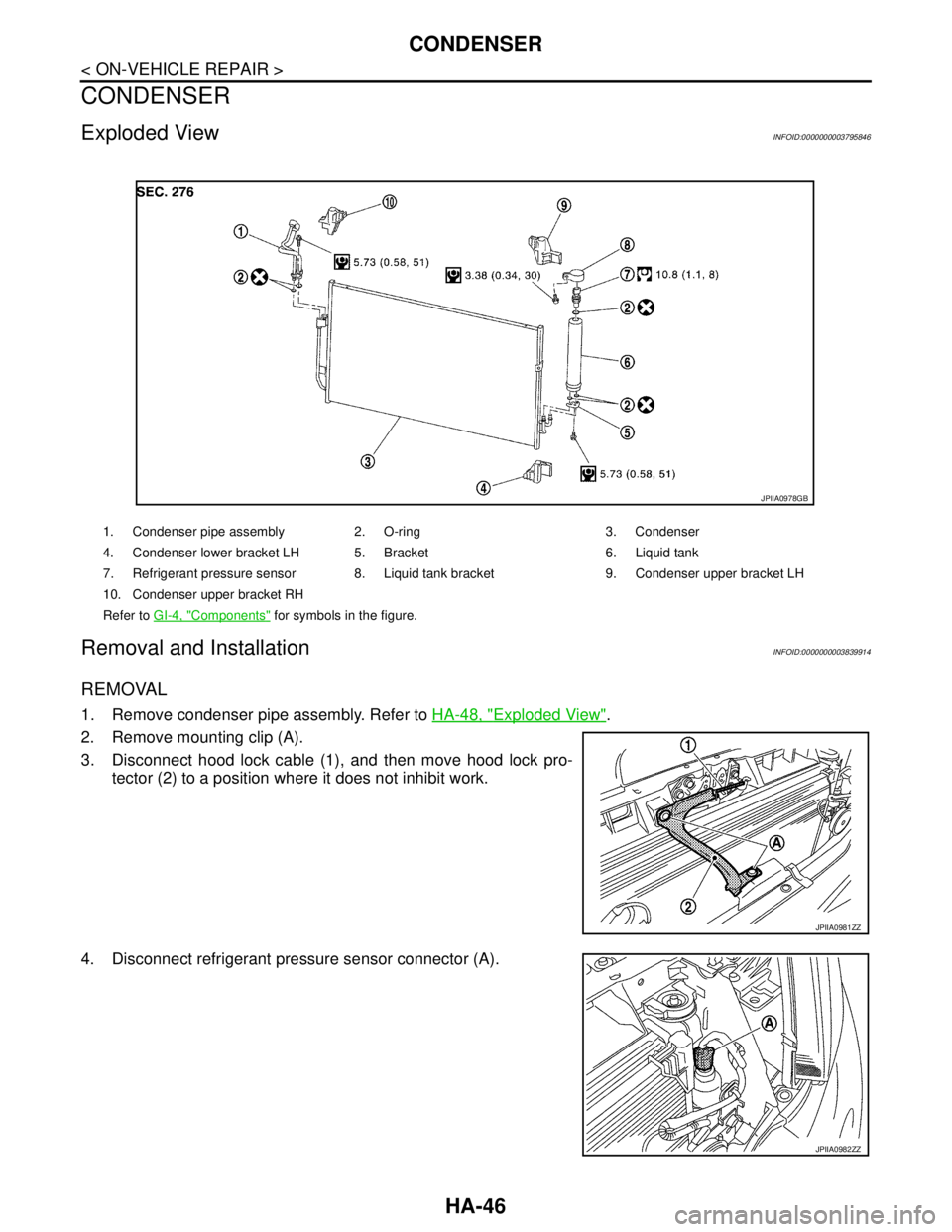
Exploded ViewINFOID:0000000003795846
Removal and InstallationINFOID:0000000003839914
REMOVAL
1. Remove condenser pipe assembly. Refer to HA-48, "Exploded View".
2. Remove mounting clip (A).
3. Disconnect hood lock cable (1), and then move hood lock pro-
tector (2) to a position where it does not inhibit work.
4. Disconnect refrigerant pressure sensor connector (A).
1. Condenser pipe assembly 2. O-ring 3. Condenser
4. Condenser lower bracket LH 5. Bracket 6. Liquid tank
7. Refrigerant pressure sensor 8. Liquid tank bracket 9. Condenser upper bracket LH
10. Condenser upper bracket RH
Refer to GI-4, "
Components" for symbols in the figure.
JPIIA0978GB
JPIIA0981ZZ
JPIIA0982ZZ
Page 2617 of 5121
HA-48
< ON-VEHICLE REPAIR >
CONDENSER PIPE ASSEMBLY
CONDENSER PIPE ASSEMBLY
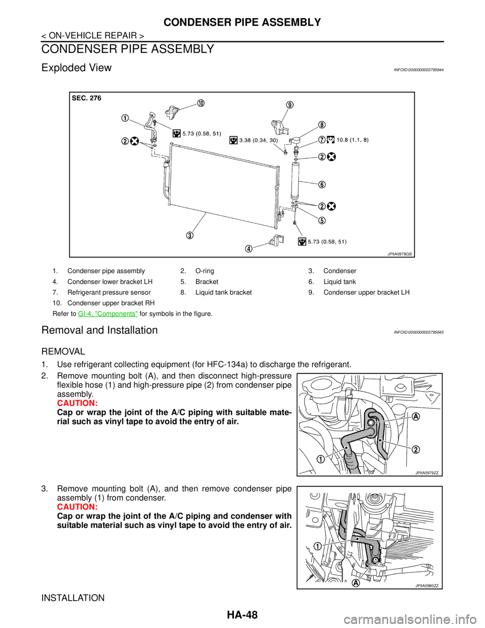
Exploded ViewINFOID:0000000003795844
Removal and InstallationINFOID:0000000003795845
REMOVAL
1. Use refrigerant collecting equipment (for HFC-134a) to discharge the refrigerant.
2. Remove mounting bolt (A), and then disconnect high-pressure
flexible hose (1) and high-pressure pipe (2) from condenser pipe
assembly.
CAUTION:
Cap or wrap the joint of the A/C piping with suitable mate-
rial such as vinyl tape to avoid the entry of air.
3. Remove mounting bolt (A), and then remove condenser pipe
assembly (1) from condenser.
CAUTION:
Cap or wrap the joint of the A/C piping and condenser with
suitable material such as vinyl tape to avoid the entry of air.
INSTALLATION
1. Condenser pipe assembly 2. O-ring 3. Condenser
4. Condenser lower bracket LH 5. Bracket 6. Liquid tank
7. Refrigerant pressure sensor 8. Liquid tank bracket 9. Condenser upper bracket LH
10. Condenser upper bracket RH
Refer to GI-4, "
Components" for symbols in the figure.
JPIIA0978GB
JPIIA0979ZZ
JPIIA0980ZZ
Page 2619 of 5121
HA-50
< ON-VEHICLE REPAIR >
LIQUID TANK
LIQUID TANK
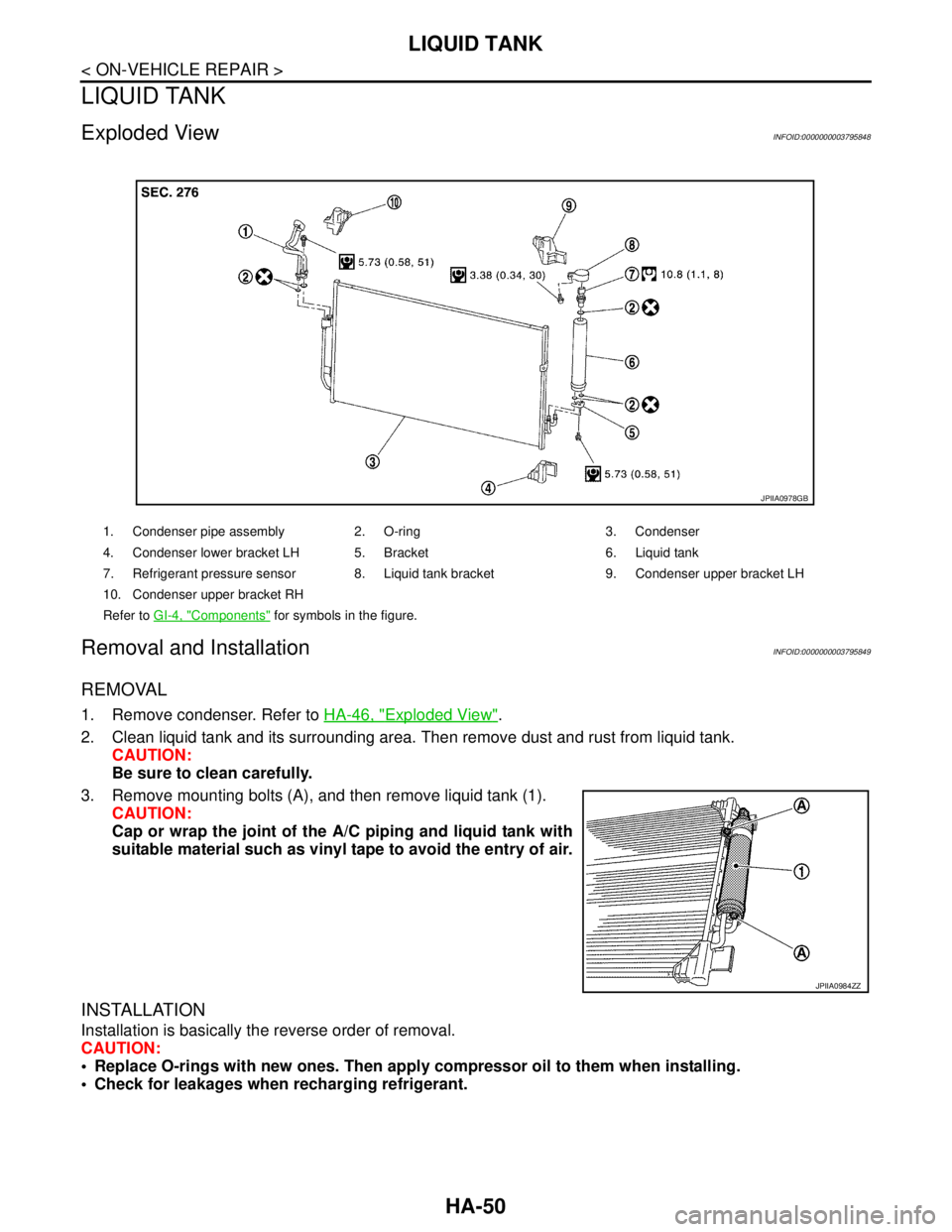
Exploded ViewINFOID:0000000003795848
Removal and InstallationINFOID:0000000003795849
REMOVAL
1. Remove condenser. Refer to HA-46, "Exploded View".
2. Clean liquid tank and its surrounding area. Then remove dust and rust from liquid tank.
CAUTION:
Be sure to clean carefully.
3. Remove mounting bolts (A), and then remove liquid tank (1).
CAUTION:
Cap or wrap the joint of the A/C piping and liquid tank with
suitable material such as vinyl tape to avoid the entry of air.
INSTALLATION
Installation is basically the reverse order of removal.
CAUTION:
Replace O-rings with new ones. Then apply compressor oil to them when installing.
Check for leakages when recharging refrigerant.
1. Condenser pipe assembly 2. O-ring 3. Condenser
4. Condenser lower bracket LH 5. Bracket 6. Liquid tank
7. Refrigerant pressure sensor 8. Liquid tank bracket 9. Condenser upper bracket LH
10. Condenser upper bracket RH
Refer to GI-4, "
Components" for symbols in the figure.
JPIIA0978GB
JPIIA0984ZZ
Page 2620 of 5121
REFRIGERANT PRESSURE SENSOR
HA-51
< ON-VEHICLE REPAIR >
C
D
E
F
G
H
J
K
L
MA
B
HA
N
O
P
REFRIGERANT PRESSURE SENSOR
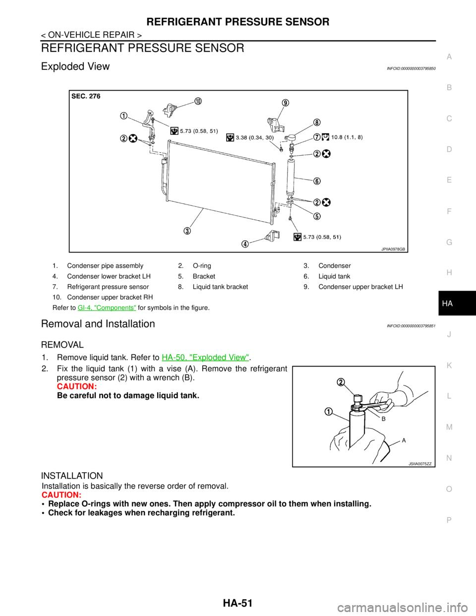
Exploded ViewINFOID:0000000003795850
Removal and InstallationINFOID:0000000003795851
REMOVAL
1. Remove liquid tank. Refer to HA-50, "Exploded View".
2. Fix the liquid tank (1) with a vise (A). Remove the refrigerant
pressure sensor (2) with a wrench (B).
CAUTION:
Be careful not to damage liquid tank.
INSTALLATION
Installation is basically the reverse order of removal.
CAUTION:
Replace O-rings with new ones. Then apply compressor oil to them when installing.
Check for leakages when recharging refrigerant.
1. Condenser pipe assembly 2. O-ring 3. Condenser
4. Condenser lower bracket LH 5. Bracket 6. Liquid tank
7. Refrigerant pressure sensor 8. Liquid tank bracket 9. Condenser upper bracket LH
10. Condenser upper bracket RH
Refer to GI-4, "
Components" for symbols in the figure.
JPIIA0978GB
JSIIA0075ZZ
Page 2622 of 5121
EVAPORATOR
HA-53
< ON-VEHICLE REPAIR >
C
D
E
F
G
H
J
K
L
MA
B
HA
N
O
P
Removal and InstallationINFOID:0000000003795855
REMOVAL
1. Remove evaporator pipe assembly. Refer to HA-54, "Exploded View".
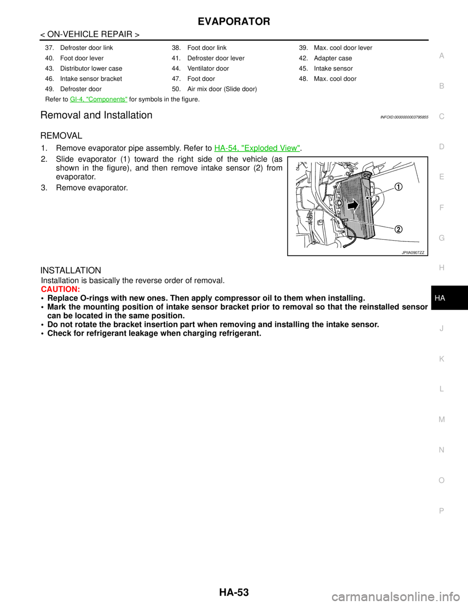
2. Slide evaporator (1) toward the right side of the vehicle (as
shown in the figure), and then remove intake sensor (2) from
evaporator.
3. Remove evaporator.
INSTALLATION
Installation is basically the reverse order of removal.
CAUTION:
Replace O-rings with new ones. Then apply compressor oil to them when installing.
Mark the mounting position of intake sensor bracket prior to removal so that the reinstalled sensor
can be located in the same position.
Do not rotate the bracket insertion part when removing and installing the intake sensor.
Check for refrigerant leakage when charging refrigerant.
37. Defroster door link 38. Foot door link 39. Max. cool door lever
40. Foot door lever 41. Defroster door lever 42. Adapter case
43. Distributor lower case 44. Ventilator door 45. Intake sensor
46. Intake sensor bracket 47. Foot door 48. Max. cool door
49. Defroster door 50. Air mix door (Slide door)
Refer to GI-4, "
Components" for symbols in the figure.
JPIIA0907ZZ
Page 2624 of 5121
EVAPORATOR PIPE ASSEMBLY
HA-55
< ON-VEHICLE REPAIR >
C
D
E
F
G
H
J
K
L
MA
B
HA
N
O
P
Removal and InstallationINFOID:0000000003795853
REMOVAL
1. Disconnect the battery cable from the negative terminal after setting the temperature (passenger side) to
18°C (60°F).
2. Use refrigerant collecting equipment (for HFC-134a) to discharge the refrigerant.
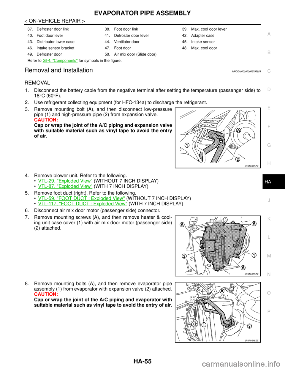
3. Remove mounting bolt (A), and then disconnect low-pressure
pipe (1) and high-pressure pipe (2) from expansion valve.
CAUTION:
Cap or wrap the joint of the A/C piping and expansion valve
with suitable material such as vinyl tape to avoid the entry
of air.
4. Remove blower unit. Refer to the following.
VTL-29, "
Exploded View" (WITHOUT 7 INCH DISPLAY)
VTL-87, "
Exploded View" (WITH 7 INCH DISPLAY)
5. Remove foot duct (right). Refer to the following.
VTL-59, "
FOOT DUCT : Exploded View" (WITHOUT 7 INCH DISPLAY)
VTL-117, "
FOOT DUCT : Exploded View" (WITH 7 INCH DISPLAY)
6. Disconnect air mix door motor (passenger side) connector.
7. Remove mounting screws (A), and then remove heater & cool-
ing unit case cover (1) with air mix door motor (passenger side)
(2) attached.
8. Remove mounting bolts (A), and then remove evaporator pipe
assembly (1) from evaporator with expansion valve (2) attached.
CAUTION:
Cap or wrap the joint of the A/C piping and evaporator with
suitable material such as vinyl tape to avoid the entry of air.
37. Defroster door link 38. Foot door link 39. Max. cool door lever
40. Foot door lever 41. Defroster door lever 42. Adapter case
43. Distributor lower case 44. Ventilator door 45. Intake sensor
46. Intake sensor bracket 47. Foot door 48. Max. cool door
49. Defroster door 50. Air mix door (Slide door)
Refer to GI-4, "
Components" for symbols in the figure.
JPIIA0915ZZ
JPIIA0563ZZ
JPIIA0546ZZ
Page 2627 of 5121
HA-58
< ON-VEHICLE REPAIR >
EXPANSION VALVE
Removal and Installation
INFOID:0000000003795857
REMOVAL
1. Use refrigerant collecting equipment (for HFC-134a) to discharge the refrigerant.
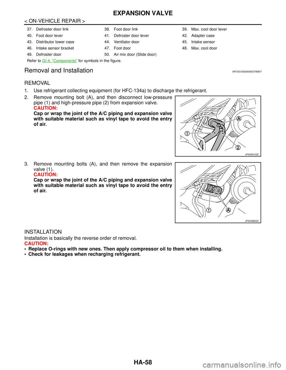
2. Remove mounting bolt (A), and then disconnect low-pressure
pipe (1) and high-pressure pipe (2) from expansion valve.
CAUTION:
Cap or wrap the joint of the A/C piping and expansion valve
with suitable material such as vinyl tape to avoid the entry
of air.
3. Remove mounting bolts (A), and then remove the expansion
valve (1).
CAUTION:
Cap or wrap the joint of the A/C piping and expansion valve
with suitable material such as vinyl tape to avoid the entry
of air.
INSTALLATION
Installation is basically the reverse order of removal.
CAUTION:
Replace O-rings with new ones. Then apply compressor oil to them when installing.
Check for leakages when recharging refrigerant.
37. Defroster door link 38. Foot door link 39. Max. cool door lever
40. Foot door lever 41. Defroster door lever 42. Adapter case
43. Distributor lower case 44. Ventilator door 45. Intake sensor
46. Intake sensor bracket 47. Foot door 48. Max. cool door
49. Defroster door 50. Air mix door (Slide door)
Refer to GI-4, "
Components" for symbols in the figure.
JPIIA0915ZZ
JPIIA0985ZZ
Page 2629 of 5121

HAC-1
VENTILATION, HEATER & AIR CONDITIONER
C
DE
F
G H
J
K L
M
SECTION HAC
A
B
HAC
N
O P
CONTENTS
HEATER & AIR CONDITIONING CONTROL SYSTEM
WITHOUT 7 INCH DISPLAY
BASIC INSPECTION ....... .............................
6
DIAGNOSIS AND REPAIR WORKFLOW ..... .....6
Work Flow ........................................................... ......6
INSPECTION AND ADJUSTMENT .....................8
Description & Inspection ..................................... ......8
Temperature Setting Trimmer .................................10
Foot Position Setting Trimmer .................................10
Inlet Port Memory Function (FRE) ..........................11
Inlet Port Memory Function (REC) ..........................11
FUNCTION DIAGNOSIS ..............................12
COMPRESSOR CONTROL FUNCTION ........ ....12
Description .......................................................... ....12
Fail-Safe ..................................................................13
Component Part Location .......................................13
Component’s Role ...................................................15
AUTOMATIC AIR CONDITIONER SYSTEM .....17
System Diagram .................................................. ....17
System Description .................................................17
Component Part Location .......................................24
Component Description ...........................................26
MODE DOOR CONTROL SYSTEM ...................28
System Diagram .................................................. ....28
System Description .................................................28
AIR MIX DOOR CONTROL SYSTEM ................30
System Diagram .................................................. ....30
System Description .................................................30
INTAKE DOOR CONTROL SYSTEM ................32
System Diagram .................................................. ....32
System Description .................................................32
BLOWER MOTOR CONTROL SYSTEM ...........34
System Diagram .................................................. ....34
System Description .................................................34
MAGNET CLUTCH CONTROL SYSTEM .........36
System Diagram .................................................. ....36
System Description ..................................................36
CAN COMMUNICATION SYSTEM ...................37
System Description ..................................................37
DIAGNOSIS SYSTEM (HVAC) .........................38
CONSULT-III Function ............................................38
COMPONENT DIAGNOSIS .........................42
U1000 CAN COMM CIRCUIT ...........................42
Description ........................................................... ....42
DTC Logic ................................................................42
Diagnosis Procedure ..............................................42
U1010 CONTROL UNIT (CAN) .........................43
Description ...............................................................43
DTC Logic ................................................................43
Diagnosis Procedure ...............................................43
B257B, B257C AMBIENT SENSOR .................44
Description ...............................................................44
DTC Logic ................................................................44
Diagnosis Procedure ...............................................45
Component Inspection .............................................46
B2578, B2579 IN-VEHICLE SENSOR ..............47
Description ...............................................................47
DTC Logic ................................................................47
Diagnosis Procedure ...............................................48
Component Inspection .............................................49
B2581, B2582 INTAKE SENSOR .....................50
Description ...............................................................50
DTC Logic ................................................................50
Diagnosis Procedure ...............................................50
Component Inspection .............................................51
B2630, B2631 SUNLOAD SENSOR .................53
Description ...............................................................53