2008 NISSAN TEANA sensor
[x] Cancel search: sensorPage 2328 of 5121
![NISSAN TEANA 2008 Service Manual BCM (BODY CONTROL MODULE)
EXL-299
< ECU DIAGNOSIS >[HALOGEN TYPE]
C
D
E
F
G
H
I
J
K
MA
B
EXL
N
O
P
111
(L/Y)GroundSteering lock unit
communicationInput/
OutputSteering lockLOCK status Battery voltage NISSAN TEANA 2008 Service Manual BCM (BODY CONTROL MODULE)
EXL-299
< ECU DIAGNOSIS >[HALOGEN TYPE]
C
D
E
F
G
H
I
J
K
MA
B
EXL
N
O
P
111
(L/Y)GroundSteering lock unit
communicationInput/
OutputSteering lockLOCK status Battery voltage](/manual-img/5/57391/w960_57391-2327.png)
BCM (BODY CONTROL MODULE)
EXL-299
< ECU DIAGNOSIS >[HALOGEN TYPE]
C
D
E
F
G
H
I
J
K
MA
B
EXL
N
O
P
111
(L/Y)GroundSteering lock unit
communicationInput/
OutputSteering lockLOCK status Battery voltage
LOCK or UNLOCK
For 15 seconds after UN-
LOCKBattery voltage
15 seconds or later after
UNLOCK0 V
11 3
(P/B)Ground Optical sensor InputIgnition switch
ONWhen bright outside of
the vehicleClose to 5 V
When dark outside of the
vehicleClose to 0 V
11 5
(L)Ground Shock sensor Input Ignition switchOFF 0 V
ACC 5.0 V
ON
2.5 V
11 6
(R/W)GroundFuse check (Stop
lamp switch)Input — Battery voltage
11 8
(O/L)Ground Stop lamp switch Input Stop lamp switchOFF (Brake pedal is not
depressed)0 V
ON (Brake pedal is de-
pressed)Battery voltage
11 9
(G/W)GroundFront door lock as-
sembly driver side
(unlock sensor)Input Driver doorLOCK status (unlock sen-
sor switch OFF)
1.1 V
UNLOCK status (unlock
sensor switch ON)0 V
121
(Y)Ground Key slot switch InputWhen the key is inserted into key slot Battery voltage
When the key is not inserted into key slot 0 V
122
(V/R)Ground ACC feedback Input Ignition switchOFF 0 V
ACC or ON Battery voltage
123
(G/W)Ground IGN feedback Input Ignition switchOFF or ACC 0 V
ON Battery voltage Te r m i n a l N o .
(Wire color)Description
ConditionVa l u e
(Approx.)
Signal nameInput/
Output +–
JMKIA0066GB
JPMIA1034GB
JPMIA0012GB
Page 2346 of 5121
![NISSAN TEANA 2008 Service Manual IPDM E/R (INTELLIGENT POWER DISTRIBUTION MODULE ENGINE ROOM)
EXL-317
< ECU DIAGNOSIS >[HALOGEN TYPE]
C
D
E
F
G
H
I
J
K
MA
B
EXL
N
O
P
11
(P)GroundSteering lock unit power
supplyOutputIgnition
switch NISSAN TEANA 2008 Service Manual IPDM E/R (INTELLIGENT POWER DISTRIBUTION MODULE ENGINE ROOM)
EXL-317
< ECU DIAGNOSIS >[HALOGEN TYPE]
C
D
E
F
G
H
I
J
K
MA
B
EXL
N
O
P
11
(P)GroundSteering lock unit power
supplyOutputIgnition
switch](/manual-img/5/57391/w960_57391-2345.png)
IPDM E/R (INTELLIGENT POWER DISTRIBUTION MODULE ENGINE ROOM)
EXL-317
< ECU DIAGNOSIS >[HALOGEN TYPE]
C
D
E
F
G
H
I
J
K
MA
B
EXL
N
O
P
11
(P)GroundSteering lock unit power
supplyOutputIgnition
switch
OFFA few seconds after open-
ing the driver doorBattery voltage
Ignition
switch
LOCKPress the push-button ig-
nition switchBattery voltage
Ignition switch ACC or ON 0 V
12
(B/W)Ground Ground — Ignition switch ON 0 V
13
(SB)Ground Fuel pump power supply OutputApproximately 1 second or more after
turning the ignition switch ON0 V
Approximately 1 second after turning
the ignition switch ON
Engine runningBattery voltage
15
(W)Ground Ignition relay power supply OutputIgnition switch OFF 0 V
Ignition switch ON Battery voltage
16
(R)Ground Front wiper auto stop InputIgnition
switch ONFront wiper stop position 0 V
Any position other than
front wiper stop positionBattery voltage
17
(V)GroundHeadlamp washer relay
controlInputIgnition
switch ONHeadlamp washer deacti-
vatedBattery voltage
Headlamp washer activat-
ed0 V
19
(Y)Ground Ignition relay power supply OutputIgnition switch OFF 0 V
Ignition switch ON Battery voltage
20
(B)Ground Ambient sensor ground Output Ignition switch ON 0 V
21
(O)Ground Ambient sensor InputIgnition switch ON
NOTE:
Changes depending to ambient tem-
perature
22
(SB)GroundRefrigerant pressure sen-
sor groundOutputEngine
running Warm-up condition
Idle speed0 V
23
(GR)GroundRefrigerant pressure sen-
sorOutputEngine
running Warm-up condition
Both A/C switch and
blower fan motor switch
ON
(Compressor operates)1.0 - 4.0 V
24
(G)
GroundRefrigerant pressure sen-
sor power supplyInputIgnition switch OFF 0 V
Ignition switch ON 5.0 V
25
(GR)Ground Ignition relay power supply OutputIgnition switch OFF 0 V
Ignition switch ON Battery voltage
27
(W)Ground Ignition relay monitor InputIgnition switch OFF or ACC Battery voltage
Ignition switch ON 0 V Te r m i n a l N o .
(Wire color)Description
ConditionVa l u e
(Approx.)
Signal nameInput/
Output +−
JSNIA0014GB
Page 2350 of 5121
![NISSAN TEANA 2008 Service Manual IPDM E/R (INTELLIGENT POWER DISTRIBUTION MODULE ENGINE ROOM)
EXL-321
< ECU DIAGNOSIS >[HALOGEN TYPE]
C
D
E
F
G
H
I
J
K
MA
B
EXL
N
O
P
88
(P)GroundWasher pump power sup-
plyOutput Ignition switch ON Ba NISSAN TEANA 2008 Service Manual IPDM E/R (INTELLIGENT POWER DISTRIBUTION MODULE ENGINE ROOM)
EXL-321
< ECU DIAGNOSIS >[HALOGEN TYPE]
C
D
E
F
G
H
I
J
K
MA
B
EXL
N
O
P
88
(P)GroundWasher pump power sup-
plyOutput Ignition switch ON Ba](/manual-img/5/57391/w960_57391-2349.png)
IPDM E/R (INTELLIGENT POWER DISTRIBUTION MODULE ENGINE ROOM)
EXL-321
< ECU DIAGNOSIS >[HALOGEN TYPE]
C
D
E
F
G
H
I
J
K
MA
B
EXL
N
O
P
88
(P)GroundWasher pump power sup-
plyOutput Ignition switch ON Battery voltage
89
(W)Ground Headlamp HI (RH) OutputIgnition
switch ON Lighting switch HI
Lighting switch PASSBattery voltage
Lighting switch OFF 0 V
90
(O)Ground Headlamp HI (LH) OutputIgnition
switch ON Lighting switch HI
Lighting switch PASSBattery voltage
Lighting switch OFF 0 V
91
(O)Ground Parking lamp (RH) OutputIgnition
switch ONLighting switch 1ST Battery voltage
Lighting switch OFF 0 V
92
(L)Ground Parking lamp (LH) OutputIgnition
switch ONLighting switch 1ST Battery voltage
Lighting switch OFF 0 V
93
(BR)GroundHeadlamp aiming motor
(RH)OutputIgnition
switch ONLighting switch 1ST Battery voltage
Lighting switch OFF 0 V
94
(Y)GroundHeadlamp aiming motor
(LH)OutputIgnition
switch ONLighting switch 1ST Battery voltage
Lighting switch OFF 0 V
99
(W)Ground Ambient sensor ground Input Ignition switch ON 0 V
100
(SB)Ground Ambient sensor OutputIgnition switch ON
NOTE:
Changes depending to ambient tem-
perature
101
(GR)GroundRefrigerant pressure sen-
sor groundInputEngine
running Warm-up condition
Idle speed0 V
102
(R)GroundRefrigerant pressure sen-
sorInputEngine
running Warm-up condition
Both A/C switch and
blower fan motor switch
ON
(Compressor operates)1.0 - 4.0 V
103
(P)GroundRefrigerant pressure sen-
sor power supplyOutputIgnition switch OFF 0 V
Ignition switch ON 5.0 V
104
(LG)
Ground Hood switch OutputClose the hood Battery voltage
Open the hood 0 V Te r m i n a l N o .
(Wire color)Description
ConditionVa l u e
(Approx.)
Signal nameInput/
Output +−
JSNIA0014GB
Page 2357 of 5121
![NISSAN TEANA 2008 Service Manual EXL-328
< SYMPTOM DIAGNOSIS >[HALOGEN TYPE]
EXTERIOR LIGHTING SYSTEM SYMPTOMS
SYMPTOM DIAGNOSIS
EXTERIOR LIGHTING SYSTEM SYMPTOMS
Symptom TableINFOID:0000000003811996
CAUTION:
Perform the self-diagnos NISSAN TEANA 2008 Service Manual EXL-328
< SYMPTOM DIAGNOSIS >[HALOGEN TYPE]
EXTERIOR LIGHTING SYSTEM SYMPTOMS
SYMPTOM DIAGNOSIS
EXTERIOR LIGHTING SYSTEM SYMPTOMS
Symptom TableINFOID:0000000003811996
CAUTION:
Perform the self-diagnos](/manual-img/5/57391/w960_57391-2356.png)
EXL-328
< SYMPTOM DIAGNOSIS >[HALOGEN TYPE]
EXTERIOR LIGHTING SYSTEM SYMPTOMS
SYMPTOM DIAGNOSIS
EXTERIOR LIGHTING SYSTEM SYMPTOMS
Symptom TableINFOID:0000000003811996
CAUTION:
Perform the self-diagnosis with CONSULT-III before the symptom diagnosis. Perform the trouble diag-
nosis if any DTC is detected.
Symptom Possible cause Inspection item
Headlamp (HI) is not
turned ON.One sideFuse
Halogen bulb (HI)
Harness between IPDM E/R
and the headlamp high
IPDM E/RHeadlamp (HI) circuit
Refer to EXL-227
.
Both sides
Symptom diagnosis
“BOTH SIDE HEADLAMPS (HI) ARE NOT TURNED ON”
Refer to EXL-331
.
Headlamp (HI) is not
turned OFF.When ignition switch is
turned ON.
When ignition switch is
turned OFF.IPDM E/R —
High beam indicator lamp is not turned ON.
[Headlamp (HI) is turned ON.]Combination meter Combination meter
Data monitor “HI-BEAM IND”
BCM (HEAD LAMP)
Active test “HEADLAMP”
Headlamp (LO) is not
turned ON.One sideFuse
Halogen bulb (LO)
Harness between IPDM E/R
and the front combination lamp
IPDM E/RHeadlamp (LO) circuit
Refer to EXL-229
.
Both sides
Symptom diagnosis
“BOTH SIDE HEADLAMPS (LO) ARE NOT TURNED ON”
Refer to EXL-332
.
Headlamp (LO) is not
turned OFF.When ignition switch is
turned ON.
When ignition switch is
turned OFF.IPDM E/R —
Each lamps are not turned ON/OFF with lighting
switch AUTO. Combination switch
Harness between the combina-
tion switch and BCM
BCMCombination switch
Refer to BCS-76
.
Optical sensor
Harness between the optical
sensor and BCM
BCMOptical sensor circuit
Refer to EXL-238
.
Front fog lamp is not
turned ON.One side Front fog lamp bulb
Harness between IPDM E/R
and the front fog lamp
Front fog lamp
IPDM E/RFront fog lamp circuit
Refer to EXL-231
.
Both sidesSymptom diagnosis
“BOTH SIDE FRONT FOG LAMPS ARE NOT TURNED ON”
Refer to EXL-334
. Front fog lamp is not turned ON.
Front fog lamp indicator is not turned ON.
(Front fog lamp is turned ON.)Combination meter Combination meter
Data monitor “FR FOG IND”
BCM (HEAD LAMP)
Active test “FR FOG LAMP”
Page 2377 of 5121
![NISSAN TEANA 2008 Service Manual EXL-348
< ON-VEHICLE REPAIR >[HALOGEN TYPE]
OPTICAL SENSOR
OPTICAL SENSOR
Exploded ViewINFOID:0000000003894363
Removal and InstallationINFOID:0000000003894364
REMOVAL
1. Insert an appropriate tool bet NISSAN TEANA 2008 Service Manual EXL-348
< ON-VEHICLE REPAIR >[HALOGEN TYPE]
OPTICAL SENSOR
OPTICAL SENSOR
Exploded ViewINFOID:0000000003894363
Removal and InstallationINFOID:0000000003894364
REMOVAL
1. Insert an appropriate tool bet](/manual-img/5/57391/w960_57391-2376.png)
EXL-348
< ON-VEHICLE REPAIR >[HALOGEN TYPE]
OPTICAL SENSOR
OPTICAL SENSOR
Exploded ViewINFOID:0000000003894363
Removal and InstallationINFOID:0000000003894364
REMOVAL
1. Insert an appropriate tool between the optical sensor and the speaker grille (RH). Pull out the optical sen-
sor upward.
2. Disconnect the optical sensor connector. And then remove the optical sensor.
INSTALLATION
Install in the reverse order of removal.
1. Optical sensor
JPLIA1092ZZ
Page 2436 of 5121

FAX-8
< ON-VEHICLE REPAIR >
FRONT WHEEL HUB AND KNUCKLE
ON-VEHICLE REPAIR
FRONT WHEEL HUB AND KNUCKLE
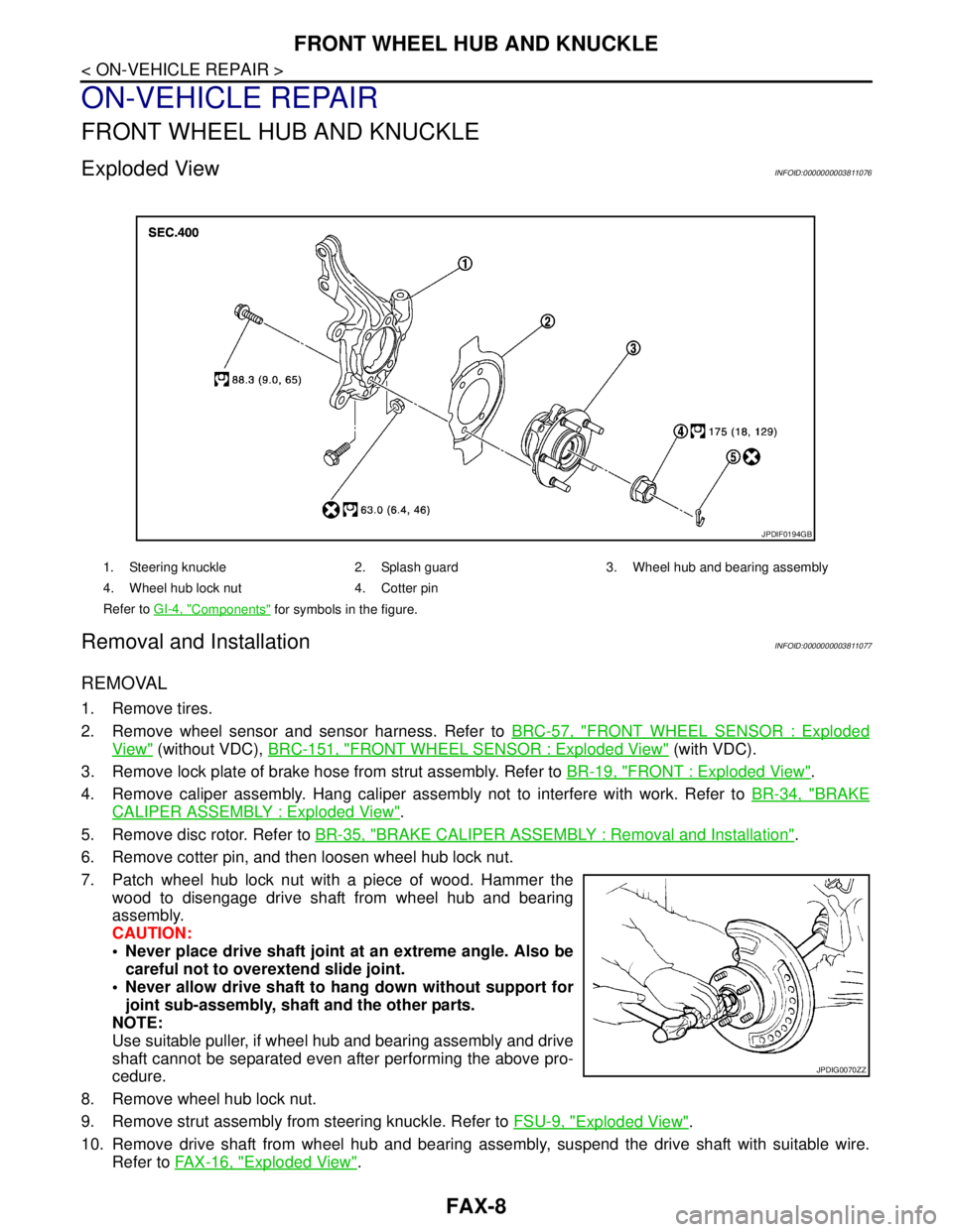
Exploded ViewINFOID:0000000003811076
Removal and InstallationINFOID:0000000003811077
REMOVAL
1. Remove tires.
2. Remove wheel sensor and sensor harness. Refer to BRC-57, "
FRONT WHEEL SENSOR : Exploded
View" (without VDC), BRC-151, "FRONT WHEEL SENSOR : Exploded View" (with VDC).
3. Remove lock plate of brake hose from strut assembly. Refer to BR-19, "
FRONT : Exploded View".
4. Remove caliper assembly. Hang caliper assembly not to interfere with work. Refer to BR-34, "
BRAKE
CALIPER ASSEMBLY : Exploded View".
5. Remove disc rotor. Refer to BR-35, "
BRAKE CALIPER ASSEMBLY : Removal and Installation".
6. Remove cotter pin, and then loosen wheel hub lock nut.
7. Patch wheel hub lock nut with a piece of wood. Hammer the
wood to disengage drive shaft from wheel hub and bearing
assembly.
CAUTION:
Never place drive shaft joint at an extreme angle. Also be
careful not to overextend slide joint.
Never allow drive shaft to hang down without support for
joint sub-assembly, shaft and the other parts.
NOTE:
Use suitable puller, if wheel hub and bearing assembly and drive
shaft cannot be separated even after performing the above pro-
cedure.
8. Remove wheel hub lock nut.
9. Remove strut assembly from steering knuckle. Refer to FSU-9, "
Exploded View".
10. Remove drive shaft from wheel hub and bearing assembly, suspend the drive shaft with suitable wire.
Refer to FAX-16, "
Exploded View".
1. Steering knuckle 2. Splash guard 3. Wheel hub and bearing assembly
4. Wheel hub lock nut 4. Cotter pin
Refer to GI-4, "
Components" for symbols in the figure.
JPDIF0194GB
JPDIG0070ZZ
Page 2437 of 5121

FRONT WHEEL HUB AND KNUCKLE
FAX-9
< ON-VEHICLE REPAIR >
C
E
F
G
H
I
J
K
L
MA
B
FA X
N
O
P
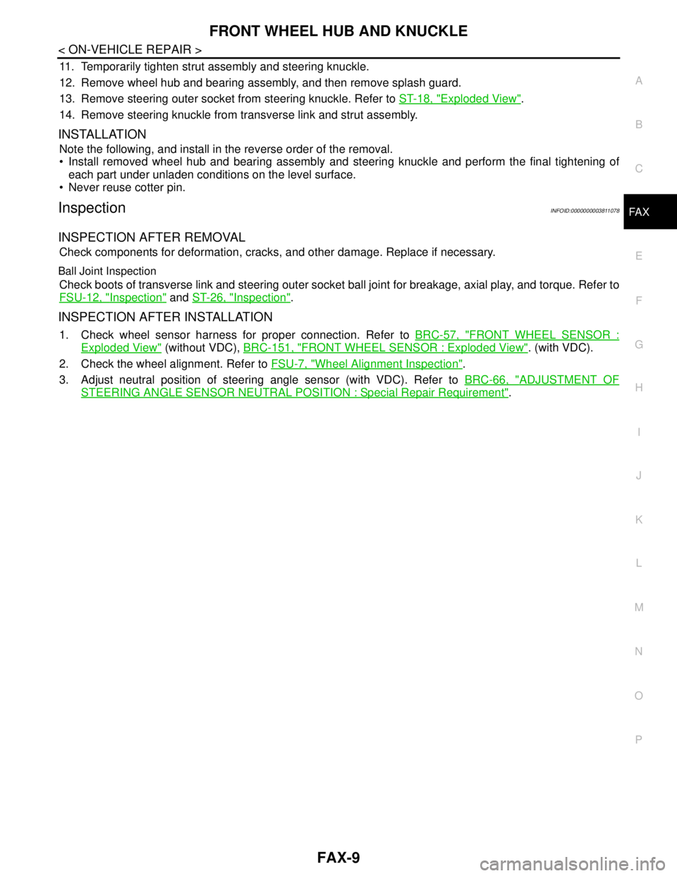
11. Temporarily tighten strut assembly and steering knuckle.
12. Remove wheel hub and bearing assembly, and then remove splash guard.
13. Remove steering outer socket from steering knuckle. Refer to ST-18, "
Exploded View".
14. Remove steering knuckle from transverse link and strut assembly.
INSTALLATION
Note the following, and install in the reverse order of the removal.
Install removed wheel hub and bearing assembly and steering knuckle and perform the final tightening of
each part under unladen conditions on the level surface.
Never reuse cotter pin.
InspectionINFOID:0000000003811078
INSPECTION AFTER REMOVAL
Check components for deformation, cracks, and other damage. Replace if necessary.
Ball Joint Inspection
Check boots of transverse link and steering outer socket ball joint for breakage, axial play, and torque. Refer to
FSU-12, "
Inspection" and ST-26, "Inspection".
INSPECTION AFTER INSTALLATION
1. Check wheel sensor harness for proper connection. Refer to BRC-57, "FRONT WHEEL SENSOR :
Exploded View" (without VDC), BRC-151, "FRONT WHEEL SENSOR : Exploded View". (with VDC).
2. Check the wheel alignment. Refer to FSU-7, "
Wheel Alignment Inspection".
3. Adjust neutral position of steering angle sensor (with VDC). Refer to BRC-66, "
ADJUSTMENT OF
STEERING ANGLE SENSOR NEUTRAL POSITION : Special Repair Requirement".
Page 2440 of 5121

FAX-12
< ON-VEHICLE REPAIR >
FRONT DRIVE SHAFT BOOT
WHEEL SIDE
WHEEL SIDE : Removal and InstallationINFOID:0000000003811080
REMOVAL
1. Remove tires.
2. Remove wheel sensor and sensor harness. Refer to BRC-57, "
FRONT WHEEL SENSOR : Exploded
View" (without VDC), BRC-151, "FRONT WHEEL SENSOR : Exploded View" (with VDC).
3. Remove lock plate of brake hose from strut assembly. Refer to BR-19, "
FRONT : Exploded View".
4. Remove caliper assembly. Hang caliper assembly not to interfere with work. Refer to BR-34, "
BRAKE
CALIPER ASSEMBLY : Exploded View".
5. Remove disc rotor. Refer to BR-35, "
BRAKE CALIPER ASSEMBLY : Removal and Installation".
6. Remove cotter pin, and then loosen wheel hub lock nut. Refer to FA X - 8 , "
Exploded View".
7. Patch wheel hub lock nut with a piece of wood. Hammer the
wood to disengage drive shaft from wheel hub and bearing
assembly.
CAUTION:
Never place drive shaft joint at an extreme angle. Also be
careful not to overextend slide joint.
Never allow drive shaft to hang down without support for
joint sub-assembly and the other parts.
NOTE:
Use suitable puller, if wheel hub and bearing assembly and drive
shaft cannot be separated even after performing the above pro-
cedure.
8. Remove wheel hub lock nut.
9. Remove steering knuckle from strut assembly. Refer to FSU-9, "
Exploded View".
10. Remove drive shaft from wheel hub and bearing assembly.
11. Remove boot bands, and then remove boot from joint sub-assembly.
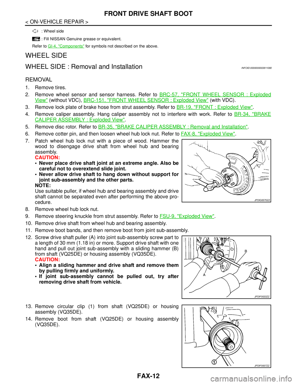
12. Screw drive shaft puller (A) into joint sub-assembly screw part to
a length of 30 mm (1.18 in) or more. Support drive shaft with one
hand and pull out joint sub-assembly with a sliding hammer (B)
from shaft (VQ25DE) or housing assembly (VQ35DE).
CAUTION:
Align a sliding hammer and drive shaft and remove them
by pulling firmly and uniformly.
If joint sub-assembly cannot be pulled out, try after
removing drive shaft from vehicle.
13. Remove circular clip (1) from shaft (VQ25DE) or housing
assembly (VQ35DE).
14. Remove boot from shaft (VQ25DE) or housing assembly
(VQ35DE).
: Wheel side
: Fill NISSAN Genuine grease or equivalent.
Refer to GI-4, "
Components" for symbols not described on the above.
JPDIG0070ZZ
JPDIF0022ZZ
JPDIF0007ZZ