2007 TOYOTA SIENNA sensor
[x] Cancel search: sensorPage 2919 of 3000

AIR CONDITIONING – AIR CONDITIONING SYSTEM (for Automatic Air Conditioning Sys-
tem)AC–19
AC
HINT:
*1: It differs depending on the user setting.
2. ACTIVE TEST
HINT:
Using the intelligent tester to perform Active Tests allows
relays, VSVs, actuators and other items to be operated
without removing any parts. This non-intrusive functional
inspection can be very useful because intermittent
operation may be discovered before parts or wiring is
disturbed. Performing Active Tests early in
troubleshooting is one way to save diagnostic time. Data
List information can be displayed while performing Active
Tests.
(a) Connect the intelligent tester to the DLC3.
A/I DAMP TARGAir inlet damper target position /
min.: -14%, max.: 113.5%Changes depending on air inlet
damper position-
A/O DAMP TARGAir outlet damper target position /
min.: -14%, max.: 113.5%Changes depending on air outlet
damper position-
BLOWER LEVELBlower motor speed level / min.:
Level 0, max.: Level 31Changes depending on blower
level-
REAR ROOM TEMPRoom temperature sensor (Rear)
/ min.: -6.5
C (20.3F), max.:
57.25C (135.05F)Actual cabin temperature (Rear) -
R-EVAP TEMP SENRr. EVAP temperature sensor
(Rear) / min.: -29.7
C (-21.46F),
max.: 59.55
C (139.19F)Actual evaporator temperature
(Rear)-
SET TEMP REARSet temperature (Rear) / min.: 0,
max. 255Actual set temperature -
ESTIMATE TEMP-REstimated temperature (Rear) /
min.: -358.4
C (-613.12F), max.:
358.4
C (677.12F)--
A/M DAMP POS-RAir mix damper position (Rear) /
min.: -14%, max.: 113.5%Changes depending on the set
temperature (Rear)-
A/O DAMP POS-RAir outlet mode damper position
(Rear) / min.: -14%, max.: 113.5%Changes depending on air outlet
damper position (Rear)-
A/M DAMP TARG-RAir mix damper target position
(Rear) / min.: -14%, max.: 113.5%Changes depending on the set
temperature (Rear)-
A/O DAMP TARG-RAir outlet damper target position
(Rear) / min.: -14%, max.: 113.5%Changes depending on air outlet
damper position (Rear)-
BLOWER LEVEL-RBlower motor speed level (Rear) /
min.: Level 0, max: Level 31Changes depending on blower
level (Rear)-
SET TEMP SHIFT Shift set temperatureChanges depending on shift set
temperature *1-
AIR INLET MODE Air inlet modeChanges depending on air inlet
mode *1-
COMPRESSOR MODE Compressor modeChanges depending on
compressor mode *1-
COMPRS/DEF MODE Compressor/DEF operation modeChanges depending on
compressor/DEF operation mode
*1-
FOOT/DEF OPER Foot/DEF auto modeChanges depending on Foot/DEF
auto mode *1-
AUTO BLOW UPFoot/DEF automatic blow up
functionChanges depending on Foot/DEF
automatic blow up function *1-
#CODESNumber of Trouble Codes / min.:
0, max.: 255-- Tester Display Measurement Item/Range Normal Condition Diagnostic Note
Page 2921 of 3000
AIR CONDITIONING – AIR CONDITIONING SYSTEM (for Automatic Air Conditioning Sys-
tem)AC–21
AC
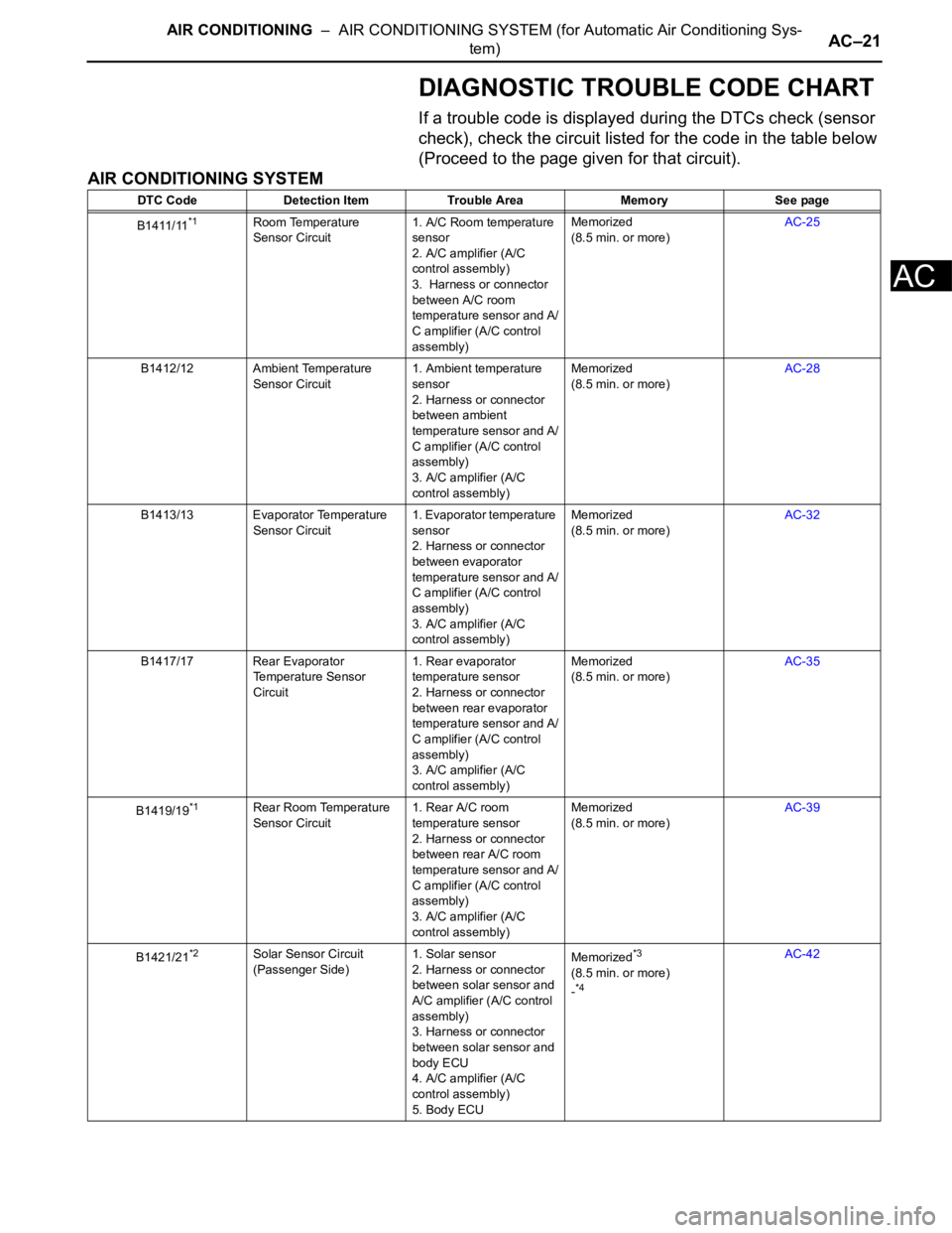
DIAGNOSTIC TROUBLE CODE CHART
If a trouble code is displayed during the DTCs check (sensor
check), check the circuit listed for the code in the table below
(Proceed to the page given for that circuit).
AIR CONDITIONING SYSTEM
DTC Code Detection Item Trouble Area Memory See page
B1411/11
*1Room Temperature
Sensor Circuit1. A/C Room temperature
sensor
2. A/C amplifier (A/C
control assembly)
3. Harness or connector
between A/C room
temperature sensor and A/
C amplifier (A/C control
assembly)Memorized
(8.5 min. or more)AC-25
B1412/12 Ambient Temperature
Sensor Circuit1. Ambient temperature
sensor
2. Harness or connector
between ambient
temperature sensor and A/
C amplifier (A/C control
assembly)
3. A/C amplifier (A/C
control assembly)Memorized
(8.5 min. or more)AC-28
B1413/13 Evaporator Temperature
Sensor Circuit1. Evaporator temperature
sensor
2. Harness or connector
between evaporator
temperature sensor and A/
C amplifier (A/C control
assembly)
3. A/C amplifier (A/C
control assembly)Memorized
(8.5 min. or more)AC-32
B1417/17 Rear Evaporator
Temperature Sensor
Circuit1. Rear evaporator
temperature sensor
2. Harness or connector
between rear evaporator
temperature sensor and A/
C amplifier (A/C control
assembly)
3. A/C amplifier (A/C
control assembly)Memorized
(8.5 min. or more)AC-35
B1419/19
*1Rear Room Temperature
Sensor Circuit1. Rear A/C room
temperature sensor
2. Harness or connector
between rear A/C room
temperature sensor and A/
C amplifier (A/C control
assembly)
3. A/C amplifier (A/C
control assembly)Memorized
(8.5 min. or more)AC-39
B1421/21
*2Solar Sensor Circuit
(Passenger Side)1. Solar sensor
2. Harness or connector
between solar sensor and
A/C amplifier (A/C control
assembly)
3. Harness or connector
between solar sensor and
body ECU
4. A/C amplifier (A/C
control assembly)
5. Body ECUMemorized*3
(8.5 min. or more)
-*4
AC-42
Page 2922 of 3000

AC–22AIR CONDITIONING – AIR CONDITIONING SYSTEM (for Automatic Air Conditioning Sys-
tem)
AC
B1422/22 Compressor Lock Sensor
Circuit1. A/C compressor (A/C
lock sensor)
2. Compressor drive belt
3. Harness or connector
between compressor and
magnetic clutch (A/C lock
sensor)
4. A/C amplifier
5. CAN communication
system
6. Multiplex
communication system
(BEAN)-AC-47
B1423/23 Pressure Sensor Circuit 1. Pressure sensor
2. Harness or connector
between pressure sensor
and A/C amplifier
3. A/C amplifier
4. Expansion valve
(blocked, stuck)
5. Condenser (blocked,
deterioration of cooling
capacity due to dirt)
6. Cooler dryer (moisture
in the refrigerant cycle
cannot be absorbed)
7. Cooling fan system
(condenser cannot be
cooled down)
8. A/C system (leaks,
blocked)-AC-51
B1424/24
*2Solar Sensor Circuit
(Driver Side)1. Solar sensor
2. Harness or connector
between solar sensor and
A/C amplifier (A/C control
assembly)
3. Harness or connector
between solar sensor and
body ECU
4. A/C amplifier (A/C
control assembly)
5. Body ECUMemorized*3
(8.5 min. or more)
-AC-64
B1431/31 Air Mix Damper Position
Sensor Circuit (Passenger
Side)1. Air mix damper position
sensor
2. A/C amplifier (A/C
control assembly)
3. Harness or connector
between air mix damper
position sensor and A/C
amplifier (A/C control
assembly)Memorized
(1 min. or more)AC-69
B1432/32 Air Inlet Damper Position
Sensor Circuit1. Air inlet damper position
sensor (Air inlet control
servo motor)
2. A/C amplifier (A/C
control assembly)
3. Harness or connector
between air inlet damper
position sensor and A/C
amplifier (A/C control
assembly)Memorized
(1 min. or more)AC-73 DTC Code Detection Item Trouble Area Memory See page
Page 2923 of 3000
AIR CONDITIONING – AIR CONDITIONING SYSTEM (for Automatic Air Conditioning Sys-
tem)AC–23
AC
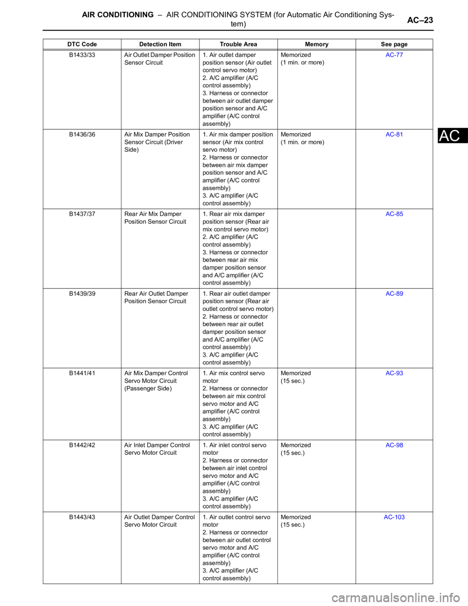
B1433/33 Air Outlet Damper Position
Sensor Circuit1. Air outlet damper
position sensor (Air outlet
control servo motor)
2. A/C amplifier (A/C
control assembly)
3. Harness or connector
between air outlet damper
position sensor and A/C
amplifier (A/C control
assembly)Memorized
(1 min. or more)AC-77
B1436/36 Air Mix Damper Position
Sensor Circuit (Driver
Side)1. Air mix damper position
sensor (Air mix control
servo motor)
2. Harness or connector
between air mix damper
position sensor and A/C
amplifier (A/C control
assembly)
3. A/C amplifier (A/C
control assembly)Memorized
(1 min. or more)AC-81
B1437/37 Rear Air Mix Damper
Position Sensor Circuit1. Rear air mix damper
position sensor (Rear air
mix control servo motor)
2. A/C amplifier (A/C
control assembly)
3. Harness or connector
between rear air mix
damper position sensor
and A/C amplifier (A/C
control assembly)AC-85
B1439/39 Rear Air Outlet Damper
Position Sensor Circuit1. Rear air outlet damper
position sensor (Rear air
outlet control servo motor)
2. Harness or connector
between rear air outlet
damper position sensor
and A/C amplifier (A/C
control assembly)
3. A/C amplifier (A/C
control assembly)AC-89
B1441/41 Air Mix Damper Control
Servo Motor Circuit
(Passenger Side)1. Air mix control servo
motor
2. Harness or connector
between air mix control
servo motor and A/C
amplifier (A/C control
assembly)
3. A/C amplifier (A/C
control assembly)Memorized
(15 sec.)AC-93
B1442/42 Air Inlet Damper Control
Servo Motor Circuit1. Air inlet control servo
motor
2. Harness or connector
between air inlet control
servo motor and A/C
amplifier (A/C control
assembly)
3. A/C amplifier (A/C
control assembly)Memorized
(15 sec.)AC-98
B1443/43 Air Outlet Damper Control
Servo Motor Circuit1. Air outlet control servo
motor
2. Harness or connector
between air outlet control
servo motor and A/C
amplifier (A/C control
assembly)
3. A/C amplifier (A/C
control assembly)Memorized
(15 sec.)AC-103 DTC Code Detection Item Trouble Area Memory See page
Page 2924 of 3000
AC–24AIR CONDITIONING – AIR CONDITIONING SYSTEM (for Automatic Air Conditioning Sys-
tem)
AC
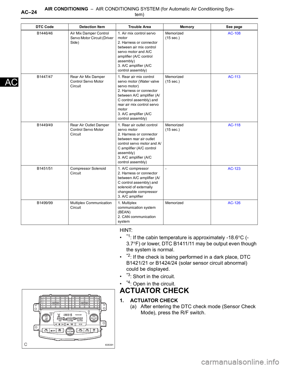
HINT:
•
*1: If the cabin temperature is approximately -18.6C (-
3.7
F) or lower, DTC B1411/11 may be output even though
the system is normal.
•
*2: If the check is being performed in a dark place, DTC
B1421/21 or B1424/24 (solar sensor circuit abnormal)
could be displayed.
•
*3: Short in the circuit.
•
*4: Open in the circuit.
ACTUATOR CHECK
1. ACTUATOR CHECK
(a) After entering the DTC check mode (Sensor Check
Mode), press the R/F switch.
B1446/46 Air Mix Damper Control
Servo Motor Circuit (Driver
Side)1. Air mix control servo
motor
2. Harness or connector
between air mix control
servo motor and A/C
amplifier (A/C control
assembly)
3. A/C amplifier (A/C
control assembly)Memorized
(15 sec.)AC-108
B1447/47 Rear Air Mix Damper
Control Servo Motor
Circuit1. Rear air mix control
servo motor (Water valve
servo motor)
2. Harness or connector
between A/C amplifier (A/
C control assembly) and
rear air mix control servo
motor
3. A/C amplifier (A/C
control assembly)Memorized
(15 sec.)AC-113
B1449/49 Rear Air Outlet Damper
Control Servo Motor
Circuit1. Rear air outlet control
servo motor
2. Harness or connector
between rear air outlet
control servo motor and A/
C amplifier (A/C control
assembly)
3. A/C amplifier (A/C
control assembly)Memorized
(15 sec.)AC-118
B1451/51 Compressor Solenoid
Circuit1. A/C compressor
2. Harness or connector
between A/C amplifier (A/
C control assembly) and
solenoid of externally
changeable compressor
3. A/C amplifier-AC-123
B1499/99 Multiplex Communication
Circuit1. Multiplex
communication system
(BEAN)
2. CAN communication
systemMemorizedAC-126 DTC Code Detection Item Trouble Area Memory See page
I035391
Page 2934 of 3000
AC–26AIR CONDITIONING – AIR CONDITIONING SYSTEM (for Automatic Air Conditioning Sys-
tem)
AC
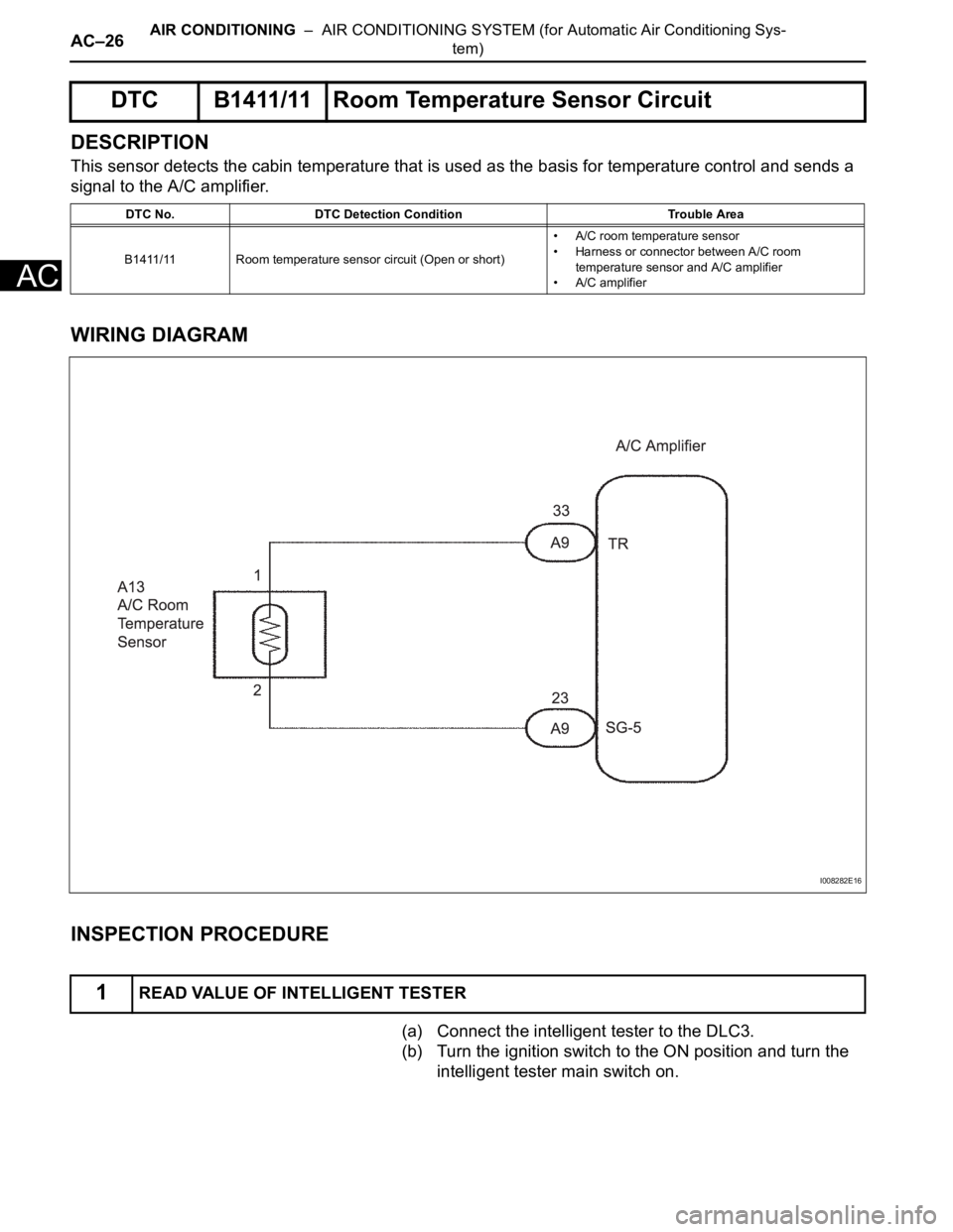
DESCRIPTION
This sensor detects the cabin temperature that is used as the basis for temperature control and sends a
signal to the A/C amplifier.
WIRING DIAGRAM
INSPECTION PROCEDURE
(a) Connect the intelligent tester to the DLC3.
(b) Turn the ignition switch to the ON position and turn the
intelligent tester main switch on.
DTC B1411/11 Room Temperature Sensor Circuit
DTC No. DTC Detection Condition Trouble Area
B1411/11 Room temperature sensor circuit (Open or short)• A/C room temperature sensor
• Harness or connector between A/C room
temperature sensor and A/C amplifier
• A/C amplifier
1READ VALUE OF INTELLIGENT TESTER
I008282E16
Page 2935 of 3000
AIR CONDITIONING – AIR CONDITIONING SYSTEM (for Automatic Air Conditioning Sys-
tem)AC–27
AC
(c) Select the item below in the DATA LIST, and read the
display on the intelligent tester.
DATA LIST / AIR CONDITIONER:
OK:
The display is as specified in the normal condition
column.
Result
B
C
A
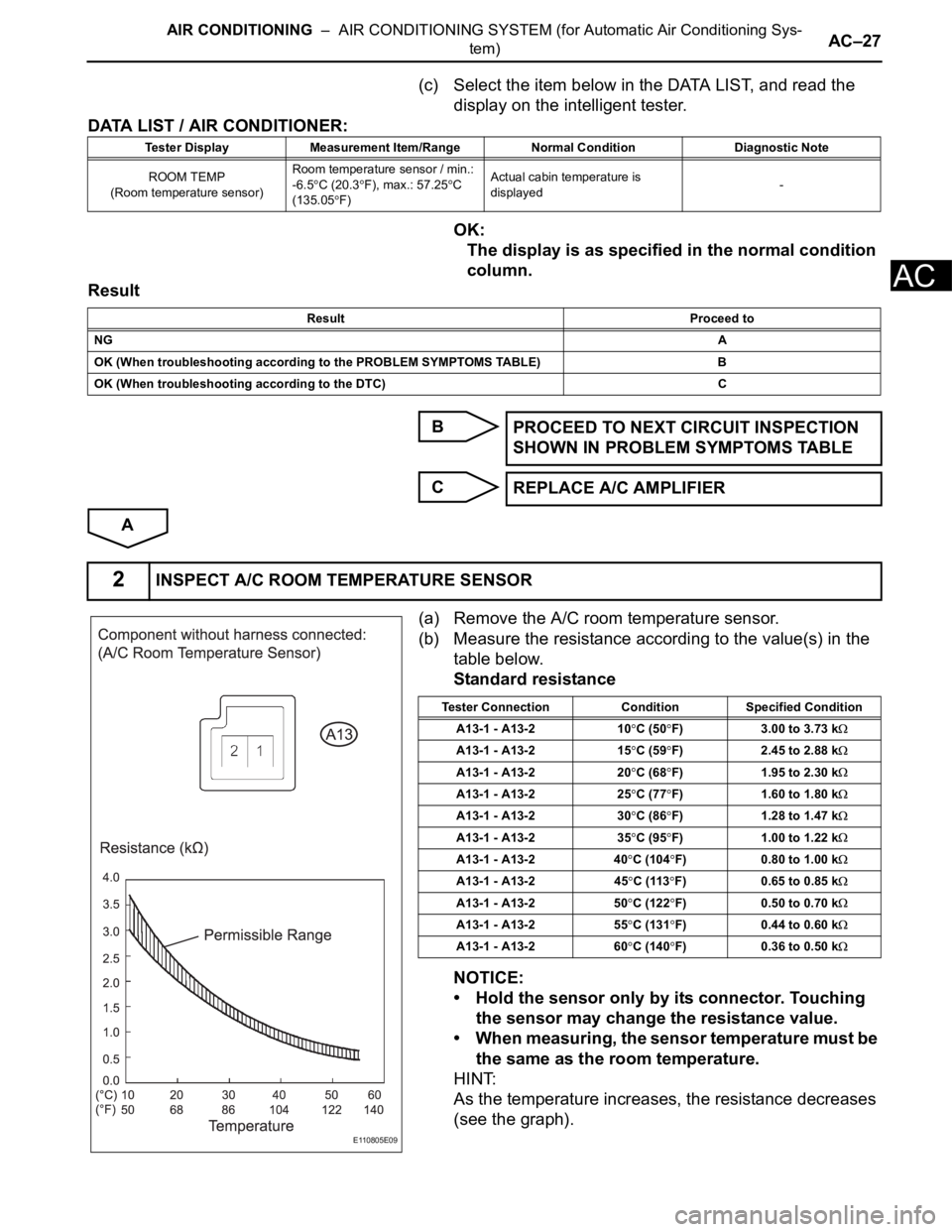
(a) Remove the A/C room temperature sensor.
(b) Measure the resistance according to the value(s) in the
table below.
Standard resistance
NOTICE:
• Hold the sensor only by its connector. Touching
the sensor may change the resistance value.
• When measuring, the sensor temperature must be
the same as the room temperature.
HINT:
As the temperature increases, the resistance decreases
(see the graph).
Tester Display Measurement Item/Range Normal Condition Diagnostic Note
ROOM TEMP
(Room temperature sensor)Room temperature sensor / min.:
-6.5
C (20.3F), max.: 57.25C
(135.05
F)Actual cabin temperature is
displayed-
Result Proceed to
NGA
OK (When troubleshooting according to the PROBLEM SYMPTOMS TABLE) B
OK (When troubleshooting according to the DTC) C
PROCEED TO NEXT CIRCUIT INSPECTION
SHOWN IN PROBLEM SYMPTOMS TABLE
REPLACE A/C AMPLIFIER
2INSPECT A/C ROOM TEMPERATURE SENSOR
E110805E09
Tester Connection Condition Specified Condition
A13-1 - A13-2 10
C (50F) 3.00 to 3.73 k
A13-1 - A13-2 15C (59F) 2.45 to 2.88 k
A13-1 - A13-2 20C (68F) 1.95 to 2.30 k
A13-1 - A13-2 25C (77F) 1.60 to 1.80 k
A13-1 - A13-2 30C (86F) 1.28 to 1.47 k
A13-1 - A13-2 35C (95F) 1.00 to 1.22 k
A13-1 - A13-2 40C (104F) 0.80 to 1.00 k
A13-1 - A13-2 45C (113F) 0.65 to 0.85 k
A13-1 - A13-2 50C (122F) 0.50 to 0.70 k
A13-1 - A13-2 55C (131F) 0.44 to 0.60 k
A13-1 - A13-2 60C (140F) 0.36 to 0.50 k
Page 2936 of 3000
AC–28AIR CONDITIONING – AIR CONDITIONING SYSTEM (for Automatic Air Conditioning Sys-
tem)
AC
NG
OK
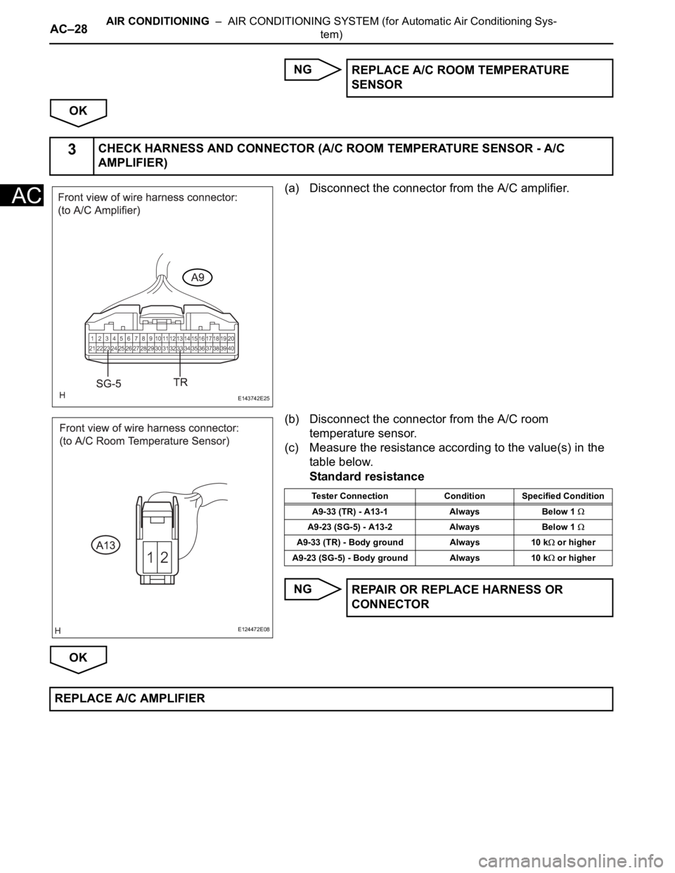
(a) Disconnect the connector from the A/C amplifier.
(b) Disconnect the connector from the A/C room
temperature sensor.
(c) Measure the resistance according to the value(s) in the
table below.
Standard resistance
NG
OKREPLACE A/C ROOM TEMPERATURE
SENSOR
3CHECK HARNESS AND CONNECTOR (A/C ROOM TEMPERATURE SENSOR - A/C
AMPLIFIER)
E143742E25
E124472E08
Tester Connection Condition Specified Condition
A9-33 (TR) - A13-1 Always Below 1
A9-23 (SG-5) - A13-2 Always Below 1
A9-33 (TR) - Body ground Always 10 k or higher
A9-23 (SG-5) - Body ground Always 10 k
or higher
REPAIR OR REPLACE HARNESS OR
CONNECTOR
REPLACE A/C AMPLIFIER