Page 2995 of 3000
RS–18SUPPLEMENTAL RESTRAINT SYSTEM – AIRBAG SYSTEM
RS
(5) Diagnostic circuit
• This circuit constantly diagnoses system
malfunctions. When a malfunction is
detected, it lights up the SRS warning light on
the combination meter assembly to inform the
driver.
(6) Memory circuit
• When a malfunction is detected in the
diagnostic circuit, it is coded and stored in the
memory circuit.
(e) SRS WARNING LIGHT
(1) The SRS warning light is located on the
combination meter assembly. It comes on to
inform the driver of system trouble when a
malfunction is detected in self-diagnosis of the
center airbag sensor assembly. Under normal
operating conditions, when the ignition switch is
turned to the ON position, it comes on for
approximately 6 seconds and then goes off.
Page 2996 of 3000
SUPPLEMENTAL RESTRAINT SYSTEM – AIRBAG SYSTEMRS–19
RS
3. DEPLOYMENT CONDITION
When the vehicle collides and the shock is greater than
the specified value, the SRS is activated automatically.
The center airbag sensor assembly includes the safing
sensor and deceleration sensor. The safing sensor was
designed to be turned on at a smaller deceleration rate
than the deceleration sensor.
(a) The center airbag sensor assembly determines
whether or not ignition is necessary based on
signals from the deceleration sensor and the front
airbag sensor (*1). If the safing sensor and
deceleration sensor turn on simultaneously, current
flows to the squibs to deploy the SRS as shown in
the illustration below.
HINT:
*1: In case of a front collision, the ignition signal
could be output with the deceleration sensor ON
signal even without a signal from the front airbag
sensor.
C109526E12
Page 2997 of 3000
RS–20SUPPLEMENTAL RESTRAINT SYSTEM – AIRBAG SYSTEM
RS
(b) The center airbag sensor assembly determines
whether or not ignition is necessary based on
signals from the side airbag sensor. If the safing
sensor and side airbag sensor turn on
simultaneously, current flows to the squib to deploy
the SRS as shown in the illustration below.
(c) The center airbag sensor assembly determines
whether or not ignition is necessary based on
signals from the rear airbag sensor. If the safing
sensor and rear airbag sensor turn on
simultaneously, current flows to the squib to deploy
the SRS as shown in the illustration below (*1).
C109527E03
C109528E03
Page 2998 of 3000
SUPPLEMENTAL RESTRAINT SYSTEM – AIRBAG SYSTEMRS–21
RS
HINT:
*1: If the front seat side airbag assembly deploys,
the curtain shield airbag assembly will also deploy,
regardless of whether the signal is output from the
rear airbag sensor.
(d) The vehicle is equipped with the function to activate
the SRS in case of vehicle rollover. A circuit to
detect vehicle rollover is built into the center airbag
sensor assembly. When the conditions for vehicle
rollover are met, the SRS is activated as shown in
the illustration below.
H045342E01
Page 2999 of 3000

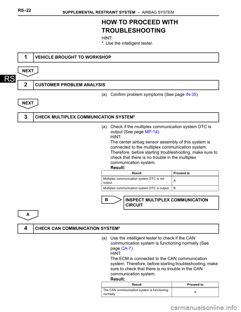
RS–22SUPPLEMENTAL RESTRAINT SYSTEM – AIRBAG SYSTEM
RS
HOW TO PROCEED WITH
TROUBLESHOOTING
HINT:
*: Use the intelligent tester.
NEXT
(a) Confirm problem symptoms (See page IN-35).
NEXT
(a) Check if the multiplex communication system DTC is
output (See page MP-14).
HINT:
The center airbag sensor assembly of this system is
connected to the multiplex communication system.
Therefore, before starting troubleshooting, make sure to
check that there is no trouble in the multiplex
communication system.
Result:
B
A
(a) Use the intelligent tester to check if the CAN
communication system is functioning normally (See
page CA-7) .
HINT:
The ECM is connected to the CAN communication
system. Therefore, before starting troubleshooting, make
sure to check that there is no trouble in the CAN
communication system.
Result:
1VEHICLE BROUGHT TO WORKSHOP
2CUSTOMER PROBLEM ANALYSIS
3CHECK MULTIPLEX COMMUNICATION SYSTEM*
Result Proceed to
Multiplex communication system DTC is not
output.A
Multiplex communication system DTC is output. B
INSPECT MULTIPLEX COMMUNICATION
CIRCUIT
4CHECK CAN COMMUNICATION SYSTEM*
Result Proceed to
The CAN communication system is functioning
normally.A