2007 TOYOTA SIENNA check engine
[x] Cancel search: check enginePage 365 of 3000

2GR-FE ENGINE CONTROL SYSTEM – SFI SYSTEMES–47
ES
KNOCK FB VAL Feedback value of knocking -
ACCEL POS #1Absolute Accelerator Pedal Position (APP)
No. 1-
ACCEL POS #2 Absolute APP No. 2 -
THROTTLE POS Throttle positionRead value with ignition switch on (Do not
start engine)
THROTTLE POS Throttle sensor positioningRead value with ignition switch on (Do not
start engine)
THROTTLE POS#2 Throttle sensor positioning #2Read value with ignition switch on (Do not
start engine)
THROTTLE MOT Throttle motor -
O2S B1 S2 Heated oxygen sensor outputPerforming INJ VOL or A/F CONTROL
function of ACTIVE TEST enables technician
to check voltage output of sensor
O2S B2 S2 Heated oxygen sensor outputPerforming INJ VOL or A/F CONTROL
function of ACTIVE TEST enables technician
to check voltage output of sensor
AFS B1 S1 A/F sensor outputPerforming INJ VOL or A/F CONTROL
function of ACTIVE TEST enables technician
to check voltage output of sensor
AFS B2 S1 A/F sensor outputPerforming INJ VOL or A/F CONTROL
function of ACTIVE TEST enables technician
to check voltage output of sensor
TOTAL FT #1 Total fuel trim of bank 1 -
TOTAL FT #2 Total fuel trim of bank 2 -
SHORT FT #1 Short-term fuel trim of bank 1Short-term fuel compensation used to
maintain air-fuel ratio at stoichiometric air-fuel
ratio
LONG FT #1 Long-term fuel trim of bank 1Overall fuel compensation carried out in long-
term to compensate for a continual deviation
of short-term fuel trim from central valve
SHORT FT #2 Short-term fuel trim of bank 2Short-term fuel compensation used to
maintain air-fuel ratio at stoichiometric air-fuel
ratio
LONG FT #2 Long-term fuel trim of bank 2Overall fuel compensation carried out in long-
term to compensate for a continual deviation
of short-term fuel trim from central valve
FUEL SYS #1 Fuel system status (bank 1)• OL (Open Loop): Has not yet satisfied
conditions to go closed loop
• CL (Closed Loop): Using heated oxygen
sensor as feedback for fuel control
• OL DRIVE: Open loop due to driving
conditions (fuel enrichment)
• OL FAULT: Open loop due to detected
system fault
• CL FAULT: Closed loop but heated
oxygen sensor, which used for fuel control
malfunctioning
FUEL SYS #2 Fuel system status (bank 2)• OL (Open Loop): Has not yet satisfied
conditions to go closed loop
• CL (Closed Loop): Using heated oxygen
sensor as feedback for fuel control
• OL DRIVE: Open loop due to driving
conditions (fuel enrichment)
• OL FAULT: Open loop due to detected
system fault
• CL FAULT: Closed loop but heated
oxygen sensor, which used for fuel control
malfunctioning
O2FT B1 S2 Fuel trim at heated oxygen sensor Same as SHORT FT #1LABEL
(Intelligent Tester Display)Measurement Item Diagnostic Note
Page 368 of 3000
ES–502GR-FE ENGINE CONTROL SYSTEM – SFI SYSTEM
ES
CHECK MODE PROCEDURE
HINT:
Intelligent tester only:
Compared to normal mode, check mode is more sensitive to
malfunctions. Therefore, check mode can detect the
malfunctions that cannot be detected by normal mode.
NOTICE:
All the stored DTCs and freeze frame data are erased if:
1) the ECM is changed from normal mode to check mode
or vice versa; or 2) the ignition switch is turned off or
turned to the ACC position from the ON position while in
check mode.
Before changing modes, always check and make a note
of any DTCs and freeze frame data.
1. CHECK MODE PROCEDURE (Using an intelligent
tester)
(a) Check and ensure the following conditions:
(1) Battery voltage 12 V or more
(2) Throttle valve fully closed
(3) The shift lever in the P or N position
(4) A/C switched OFF
(b) Turn the ignition switch off.
(c) Connect an intelligent tester to the DLC3.
(d) Turn the ignition switch to the ON position.
(e) Turn the tester ON.
(f) Select the following menu items: DIAGNOSIS /
ENHANCED OBD II / CHECK MODE.
(g) Switch the ECM from normal mode to check mode.
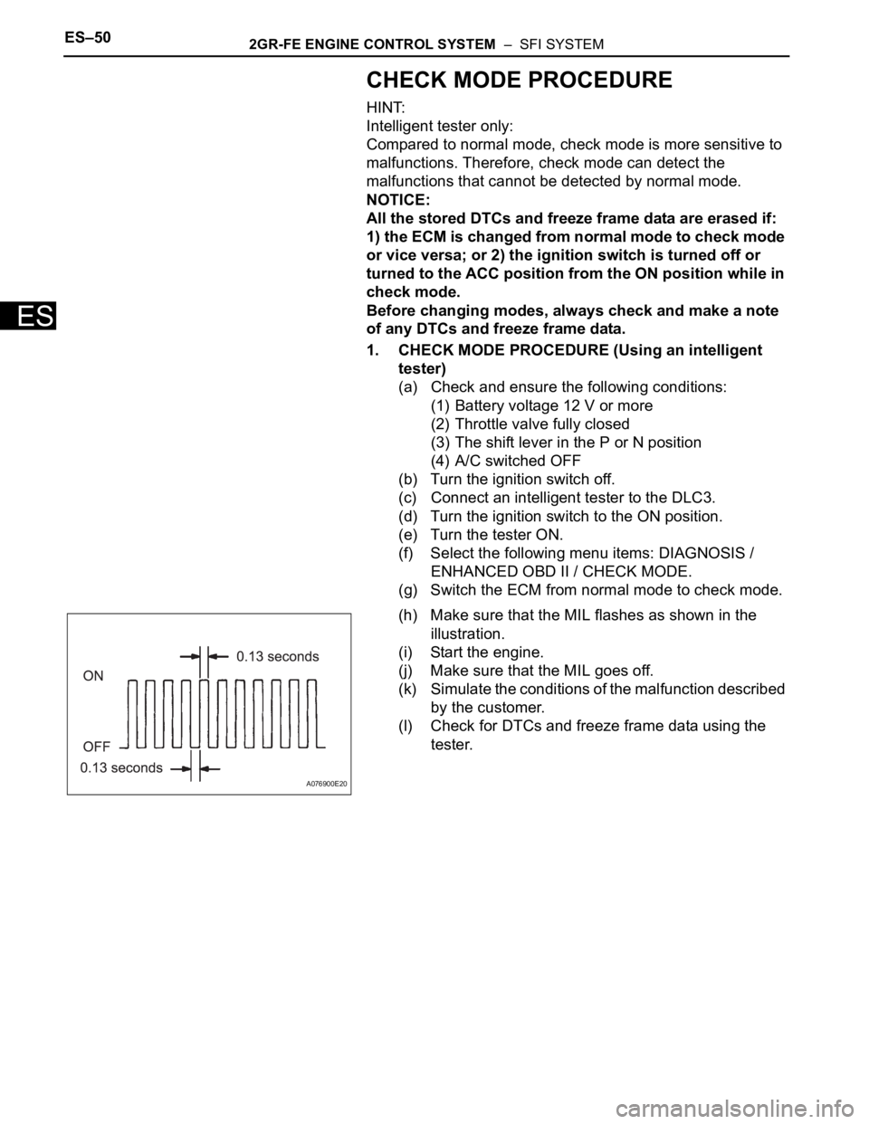
(h) Make sure that the MIL flashes as shown in the
illustration.
(i) Start the engine.
(j) Make sure that the MIL goes off.
(k) Simulate the conditions of the malfunction described
by the customer.
(l) Check for DTCs and freeze frame data using the
tester.
A076900E20
Page 370 of 3000
ES–642GR-FE ENGINE CONTROL SYSTEM – SFI SYSTEM
ES
DIAGNOSTIC TROUBLE CODE CHART
HINT:
The parameters listed in the chart may not confirm exactly to
those read during the DTC check due to the type of
instrument or other factors.
If a trouble code is displayed during the DTC check in the
check mode, check the circuit for the code listed in the table
below. For details of each code, refer to the "See page"
column in the DTC chart.
SFI SYSTEM:
DTC Code Detection Item Suspected Trouble
AreaMIL Memory See page
P0010 Camshaft Position
"A" Actuator Circuit
(Bank 1)1. Open or short in
OCV for intake
camshaft (bank 1)
circuit
2. OCV for intake
camshaft (bank 1)
3. ECMComes on DTC storedES-75
P0011 Camshaft Position
"A" - Timing Over-
Advanced or System
Performance (Bank
1)1. Valve timing
2. OCV for intake
camshaft
3. OCV filter
4. Intake camshaft
(bank 1) timing gear
assembly
5. ECMComes on DTC storedES-80
P0012 Camshaft Position
"A" - Timing Over-
Retarded (Bank 1)1. Valve timing
2. OCV for intake
camshaft
3. OCV filter
4. Intake camshaft
(bank 2) timing gear
assembly
5. ECMComes on DTC storedES-80
P0013 Camshaft Position
"B" Actuator Circuit /
Open (Bank 1)1. Open or short in
OCV for exhaust
camshaft (bank 1)
circuit
2. OCV for exhaust
camshaft (bank 1)
3. ECMComes on DTC storedES-87
P0014 Camshaft Position
"B" - Timing Over-
Advanced or System
Performance (Bank
1)1. Valve timing
2. OCV for exhaust
camshaft
3. OCV filter
4. Exhaust camshaft
timing gear assembly
5. ECMComes on DTC storedES-92
P0015 Camshaft Position
"B" - Timing Over-
Retarded (Bank 1)1. Valve timing
2. OCV for exhaust
camshaft
3. OCV filter
4. Exhaust camshaft
timing gear assembly
5. ECMComes on DTC storedES-92
P0016 Crankshaft Position -
Camshaft Position
Correlation (Bank 1
Sensor A)1. Mechanical system
(Timing chain has
jumped teeth or chain
stretched)
2. ECMComes on DTC storedES-98
Page 391 of 3000
2GR-FE ENGINE CONTROL SYSTEM – SFI SYSTEMES–85
ES
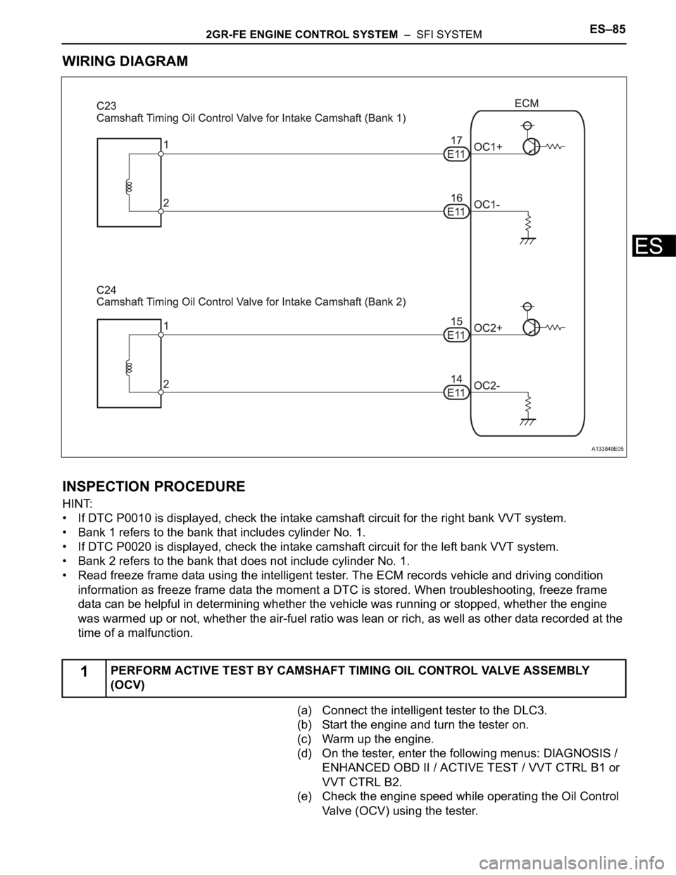
WIRING DIAGRAM
INSPECTION PROCEDURE
HINT:
• If DTC P0010 is displayed, check the intake camshaft circuit for the right bank VVT system.
• Bank 1 refers to the bank that includes cylinder No. 1.
• If DTC P0020 is displayed, check the intake camshaft circuit for the left bank VVT system.
• Bank 2 refers to the bank that does not include cylinder No. 1.
• Read freeze frame data using the intelligent tester. The ECM records vehicle and driving condition
information as freeze frame data the moment a DTC is stored. When troubleshooting, freeze frame
data can be helpful in determining whether the vehicle was running or stopped, whether the engine
was warmed up or not, whether the air-fuel ratio was lean or rich, as well as other data recorded at the
time of a malfunction.
(a) Connect the intelligent tester to the DLC3.
(b) Start the engine and turn the tester on.
(c) Warm up the engine.
(d) On the tester, enter the following menus: DIAGNOSIS /
ENHANCED OBD II / ACTIVE TEST / VVT CTRL B1 or
VVT CTRL B2.
(e) Check the engine speed while operating the Oil Control
Valve (OCV) using the tester.
1PERFORM ACTIVE TEST BY CAMSHAFT TIMING OIL CONTROL VALVE ASSEMBLY
(OCV)
A133849E05
Page 392 of 3000
ES–862GR-FE ENGINE CONTROL SYSTEM – SFI SYSTEM
ES
OK
OK
NG
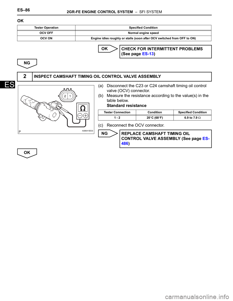
(a) Disconnect the C23 or C24 camshaft timing oil control
valve (OCV) connector.
(b) Measure the resistance according to the value(s) in the
table below.
Standard resistance
(c) Reconnect the OCV connector.
NG
OK
Tester Operation Specified Condition
OCV OFF Normal engine speed
OCV ON Engine idles roughly or stalls (soon after OCV switched from OFF to ON)
CHECK FOR INTERMITTENT PROBLEMS
(See page ES-13)
2INSPECT CAMSHAFT TIMING OIL CONTROL VALVE ASSEMBLY
A095415E03
Tester Connection Condition Specified Condition
1 - 2 20
C (68F) 6.9 to 7.9
REPLACE CAMSHAFT TIMING OIL
CONTROL VALVE ASSEMBLY (See page ES-
486)
Page 393 of 3000
2GR-FE ENGINE CONTROL SYSTEM – SFI SYSTEMES–87
ES
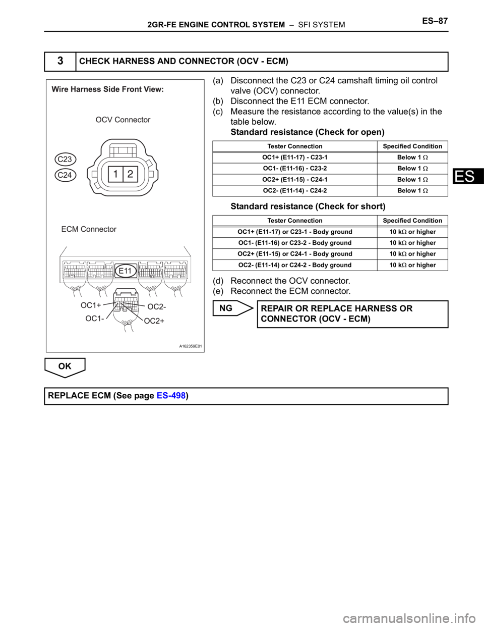
(a) Disconnect the C23 or C24 camshaft timing oil control
valve (OCV) connector.
(b) Disconnect the E11 ECM connector.
(c) Measure the resistance according to the value(s) in the
table below.
Standard resistance (Check for open)
Standard resistance (Check for short)
(d) Reconnect the OCV connector.
(e) Reconnect the ECM connector.
NG
OK
3CHECK HARNESS AND CONNECTOR (OCV - ECM)
A162359E01
Tester Connection Specified Condition
OC1+ (E11-17) - C23-1 Below 1
OC1- (E11-16) - C23-2 Below 1
OC2+ (E11-15) - C24-1 Below 1
OC2- (E11-14) - C24-2 Below 1
Tester Connection Specified Condition
OC1+ (E11-17) or C23-1 - Body ground 10 k
or higher
OC1- (E11-16) or C23-2 - Body ground 10 k
or higher
OC2+ (E11-15) or C24-1 - Body ground 10 k
or higher
OC2- (E11-14) or C24-2 - Body ground 10 k
or higher
REPAIR OR REPLACE HARNESS OR
CONNECTOR (OCV - ECM)
REPLACE ECM (See page ES-498)
Page 394 of 3000
ES–882GR-FE ENGINE CONTROL SYSTEM – SFI SYSTEM
ES
HINT:
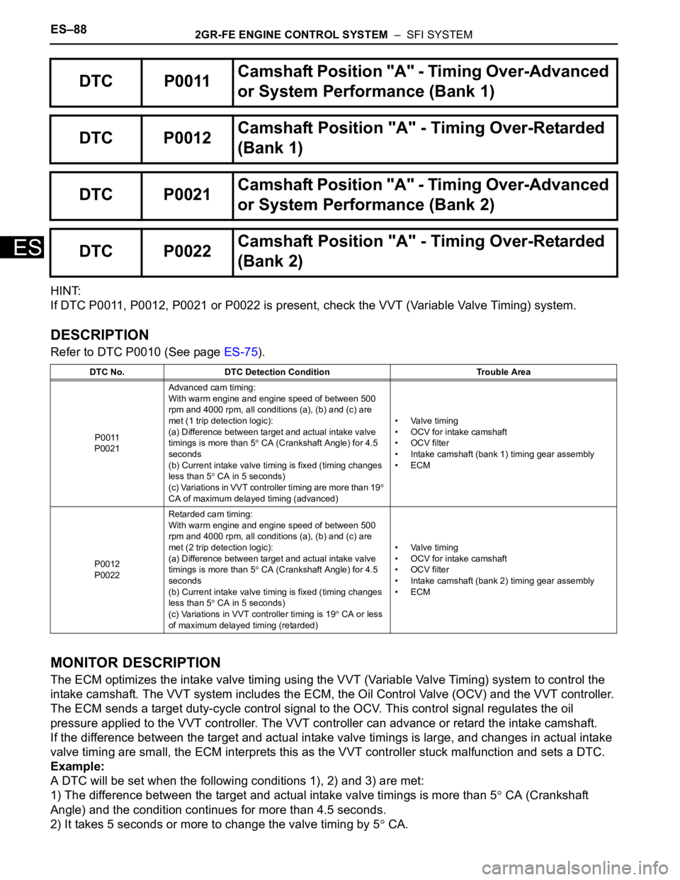
If DTC P0011, P0012, P0021 or P0022 is present, check the VVT (Variable Valve Timing) system.
DESCRIPTION
Refer to DTC P0010 (See page ES-75).
MONITOR DESCRIPTION
The ECM optimizes the intake valve timing using the VVT (Variable Valve Timing) system to control the
intake camshaft. The VVT system includes the ECM, the Oil Control Valve (OCV) and the VVT controller.
The ECM sends a target duty-cycle control signal to the OCV. This control signal regulates the oil
pressure applied to the VVT controller. The VVT controller can advance or retard the intake camshaft.
If the difference between the target and actual intake valve timings is large, and changes in actual intake
valve timing are small, the ECM interprets this as the VVT controller stuck malfunction and sets a DTC.
Example:
A DTC will be set when the following conditions 1), 2) and 3) are met:
1) The difference between the target and actual intake valve timings is more than 5
CA (Crankshaft
Angle) and the condition continues for more than 4.5 seconds.
2) It takes 5 seconds or more to change the valve timing by 5
CA.
DTC P0011Camshaft Position "A" - Timing Over-Advanced
or System Performance (Bank 1)
DTC P0012Camshaft Position "A" - Timing Over-Retarded
(Bank 1)
DTC P0021Camshaft Position "A" - Timing Over-Advanced
or System Performance (Bank 2)
DTC P0022Camshaft Position "A" - Timing Over-Retarded
(Bank 2)
DTC No. DTC Detection Condition Trouble Area
P0011
P0021Advanced cam timing:
With warm engine and engine speed of between 500
rpm and 4000 rpm, all conditions (a), (b) and (c) are
met (1 trip detection logic):
(a) Difference between target and actual intake valve
timings is more than 5
CA (Crankshaft Angle) for 4.5
seconds
(b) Current intake valve timing is fixed (timing changes
less than 5
CA in 5 seconds)
(c) Variations in VVT controller timing are more than 19
CA of maximum delayed timing (advanced)• Valve timing
• OCV for intake camshaft
• OCV filter
• Intake camshaft (bank 1) timing gear assembly
•ECM
P0012
P0022Retarded cam timing:
With warm engine and engine speed of between 500
rpm and 4000 rpm, all conditions (a), (b) and (c) are
met (2 trip detection logic):
(a) Difference between target and actual intake valve
timings is more than 5
CA (Crankshaft Angle) for 4.5
seconds
(b) Current intake valve timing is fixed (timing changes
less than 5
CA in 5 seconds)
(c) Variations in VVT controller timing is 19
CA or less
of maximum delayed timing (retarded)• Valve timing
• OCV for intake camshaft
• OCV filter
• Intake camshaft (bank 2) timing gear assembly
•ECM
Page 396 of 3000

ES–902GR-FE ENGINE CONTROL SYSTEM – SFI SYSTEM
ES
HINT:
• If DTC P0011 or P0012 is displayed, check the bank 1 VVT system circuit.
• Bank 1 refers to the bank that includes cylinder No. 1.
• If DTC P0021 or P0022 is displayed, check the bank 2 VVT system circuit.
• Bank 2 refers to the bank that does not include cylinder No. 1.
• Read freeze frame data using the intelligent tester. The ECM records vehicle and driving condition
information as freeze frame data the moment a DTC is stored. When troubleshooting, freeze frame
data can be helpful in determining whether the vehicle was running or stopped, whether the engine
was warmed up or not, whether the air-fuel ratio was lean or rich, as well as other data recorded at the
time of a malfunction.
(a) Connect the intelligent tester to the DLC3.
(b) Turn the ignition switch to the ON position and turn the
tester on.
(c) Select the following menu items: DIAGNOSIS /
ENHANCED OBD II / DTC INFO / CURRENT CODES.
(d) Read the DTCs.
Result
HINT:
If any DTCs other than P0011, P0012, P0021 or P0022
are output, troubleshoot those DTCs first.
B
A
(a) Connect the intelligent tester to the DLC3.
(b) Start the engine and turn the tester on.
(c) Warm up the engine.
(d) Select the following menu items on the tester:
DIAGNOSIS / ENHANCED OBD II / ACTIVE TEST /
VVT CTRL B1.
(e) Check the engine speed while operating the Oil Control
Valve (OCV) using the tester.
OK
NG
OK
1CHECK ANY OTHER DTCS OUTPUT (IN ADDITION TO DTC P0011, P0012, P0021 OR
P0022)
Display (DTC Output) Proceed to
P0011, P0012, P0021 or P0022 A
P0011, P0012, P0021 or P0022 and other DTCs B
GO TO DTC CHART (See page ES-56)
2PERFORM ACTIVE TEST BY INTELLIGENT TESTER (OPERATE OCV)
Tester Operation Specified Condition
OCV OFF Normal engine idle speed
OCV ON Engine idles roughly or stalls (soon after OCV switched from OFF to ON)
Go to step 4