Page 418 of 3000

ES–1122GR-FE ENGINE CONTROL SYSTEM – SFI SYSTEM
ES
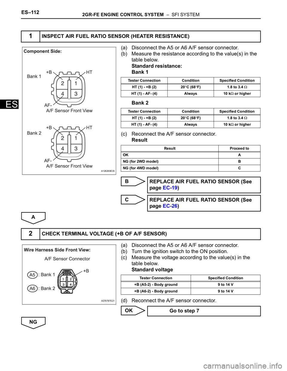
(a) Disconnect the A5 or A6 A/F sensor connector.
(b) Measure the resistance according to the value(s) in the
table below.
Standard resistance:
Bank 1
Bank 2
(c) Reconnect the A/F sensor connector.
Result
B
C
A
(a) Disconnect the A5 or A6 A/F sensor connector.
(b) Turn the ignition switch to the ON position.
(c) Measure the voltage according to the value(s) in the
table below.
Standard voltage
(d) Reconnect the A/F sensor connector.
OK
NG
1INSPECT AIR FUEL RATIO SENSOR (HEATER RESISTANCE)
A126269E35
Tester Connection Condition Specified Condition
HT (1) - +B (2) 20
C (68F) 1.8 to 3.4
HT (1) - AF- (4) Always 10 k or higher
Tester Connection Condition Specified Condition
HT (1) - +B (2) 20
C (68F) 1.8 to 3.4
HT (1) - AF- (4) Always 10 k or higher
Result Proceed to
OK A
NG (for 2WD model) B
NG (for 4WD model) C
REPLACE AIR FUEL RATIO SENSOR (See
page EC-19)
REPLACE AIR FUEL RATIO SENSOR (See
page EC-26)
2CHECK TERMINAL VOLTAGE (+B OF A/F SENSOR)
A076787E21
Tester Connection Specified Condition
+B (A5-2) - Body ground 9 to 14 V
+B (A6-2) - Body ground 9 to 14 V
Go to step 7
Page 420 of 3000

ES–1142GR-FE ENGINE CONTROL SYSTEM – SFI SYSTEM
ES
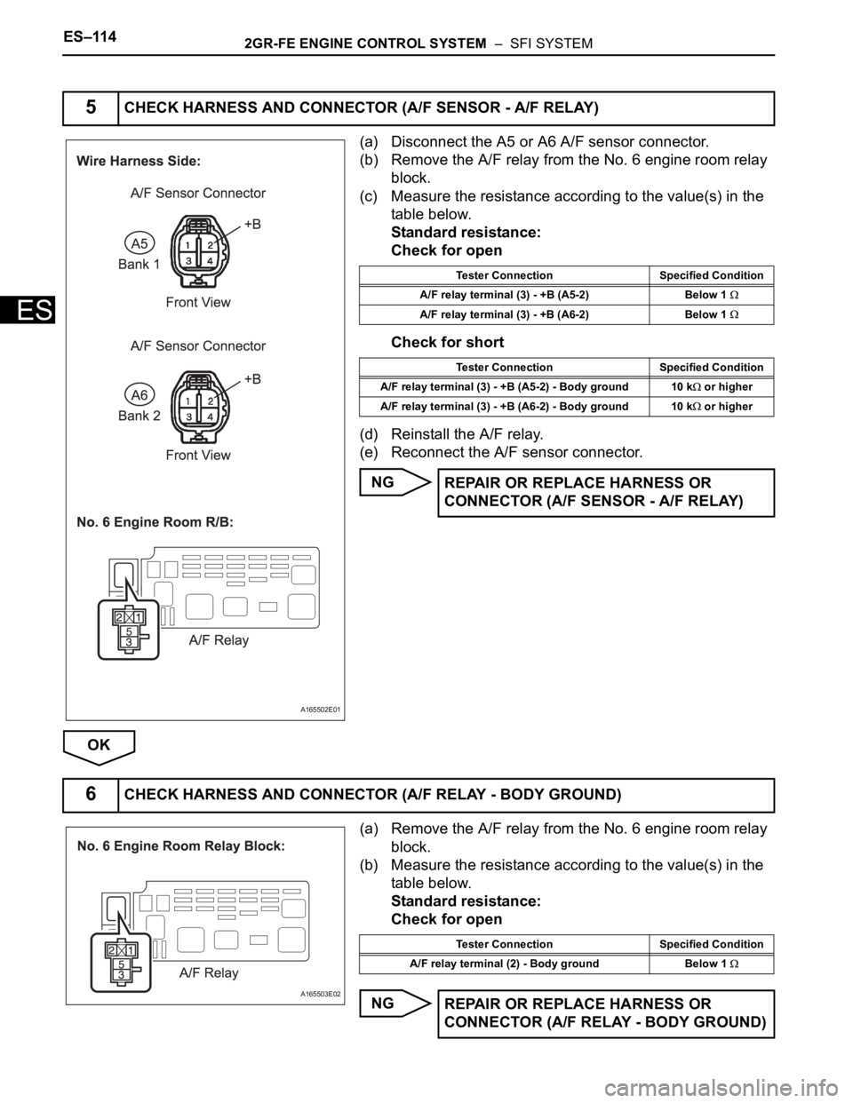
(a) Disconnect the A5 or A6 A/F sensor connector.
(b) Remove the A/F relay from the No. 6 engine room relay
block.
(c) Measure the resistance according to the value(s) in the
table below.
Standard resistance:
Check for open
Check for short
(d) Reinstall the A/F relay.
(e) Reconnect the A/F sensor connector.
NG
OK
(a) Remove the A/F relay from the No. 6 engine room relay
block.
(b) Measure the resistance according to the value(s) in the
table below.
Standard resistance:
Check for open
NG
5CHECK HARNESS AND CONNECTOR (A/F SENSOR - A/F RELAY)
A165502E01
Tester Connection Specified Condition
A/F relay terminal (3) - +B (A5-2) Below 1
A/F relay terminal (3) - +B (A6-2) Below 1
Tester Connection Specified Condition
A/F relay terminal (3) - +B (A5-2) - Body ground 10 k
or higher
A/F relay terminal (3) - +B (A6-2) - Body ground 10 k
or higher
REPAIR OR REPLACE HARNESS OR
CONNECTOR (A/F SENSOR - A/F RELAY)
6CHECK HARNESS AND CONNECTOR (A/F RELAY - BODY GROUND)
A165503E02
Tester Connection Specified Condition
A/F relay terminal (2) - Body ground Below 1
REPAIR OR REPLACE HARNESS OR
CONNECTOR (A/F RELAY - BODY GROUND)
Page 421 of 3000

2GR-FE ENGINE CONTROL SYSTEM – SFI SYSTEMES–115
ES
OK
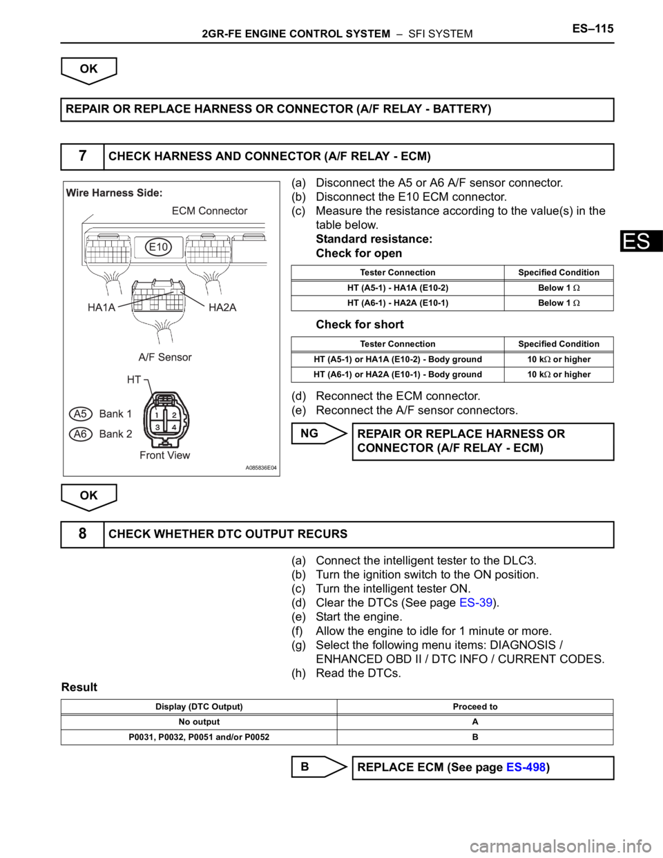
(a) Disconnect the A5 or A6 A/F sensor connector.
(b) Disconnect the E10 ECM connector.
(c) Measure the resistance according to the value(s) in the
table below.
Standard resistance:
Check for open
Check for short
(d) Reconnect the ECM connector.
(e) Reconnect the A/F sensor connectors.
NG
OK
(a) Connect the intelligent tester to the DLC3.
(b) Turn the ignition switch to the ON position.
(c) Turn the intelligent tester ON.
(d) Clear the DTCs (See page ES-39).
(e) Start the engine.
(f) Allow the engine to idle for 1 minute or more.
(g) Select the following menu items: DIAGNOSIS /
ENHANCED OBD II / DTC INFO / CURRENT CODES.
(h) Read the DTCs.
Result
B REPAIR OR REPLACE HARNESS OR CONNECTOR (A/F RELAY - BATTERY)
7CHECK HARNESS AND CONNECTOR (A/F RELAY - ECM)
A085836E04
Tester Connection Specified Condition
HT (A5-1) - HA1A (E10-2) Below 1
HT (A6-1) - HA2A (E10-1) Below 1
Tester Connection Specified Condition
HT (A5-1) or HA1A (E10-2) - Body ground 10 k
or higher
HT (A6-1) or HA2A (E10-1) - Body ground 10 k
or higher
REPAIR OR REPLACE HARNESS OR
CONNECTOR (A/F RELAY - ECM)
8CHECK WHETHER DTC OUTPUT RECURS
Display (DTC Output) Proceed to
No output A
P0031, P0032, P0051 and/or P0052 B
REPLACE ECM (See page ES-498)
Page 422 of 3000
ES–1162GR-FE ENGINE CONTROL SYSTEM – SFI SYSTEM
ES
A
CHECK FOR INTERMITTENT PROBLEMS
Page 424 of 3000

ES–1182GR-FE ENGINE CONTROL SYSTEM – SFI SYSTEM
ES
HINT:
• Bank 1 refers to the bank that includes cylinder No. 1.
• Bank 2 refers to the bank that does not include cylinder No. 1.
• Sensor 1 refers to the sensor closest to the engine assembly.
• Sensor 2 refers to the sensor furthest away from the engine assembly.
MONITOR DESCRIPTION
The sensing position of the Heated Oxygen (HO2) sensor has a zirconia element which is used to detect
the oxygen concentration in the exhaust gas. If the zirconia element is at the appropriate temperature,
and the difference between the oxygen concentrations surrounding the inside and outside surfaces of the
sensor is large, the zirconia element generates voltage signals. In order to increase the oxygen
concentration detecting capacity of the zirconia element, the ECM supplements the heat from the exhaust
with heat from a heating element inside the sensor.
Heated oxygen sensor heater range check (P0037, P0038, P0057 and P0058):
The ECM monitors the current applied to the O2 sensor heater to check the heater for malfunctions. If the
current is below the threshold value, the ECM will determine that there is an open circuit in the heater. If
the current is above the threshold value, the ECM will determine that there is a short circuit in the heater.
Example:
The ECM sets DTC P0038 or P0058 when the current in the HO2 sensor heater is more than 2 A.
Conversely, when the heater current is less than 0.3 A, DTC P0037 or P0057 is set.
Heated oxygen sensor heater performance (P0141 and P0161):
After the accumulated heater ON time exceeds 100 seconds, the ECM calculates the heater resistance
using the battery voltage and the current applied to the heater. If the resistance is above the threshold
value, the ECM will determine that there is a malfunction in the HO2S heater and set DTC P0141 and
P0161.
MONITOR STRATEGY
DTC No. DTC Detection Condition Trouble Area
P0037
P0057Heated Oxygen (HO2) sensor heater current is less
than 0.3 A (1 trip detection logic)• Open in HO2 sensor heater circuit
• HO2 sensor heater
• EFI relay
•ECM
P0038
P0058Heated Oxygen (HO2) sensor heater current is more
than 2 A (1 trip detection logic)• Open in HO2 sensor heater circuit
• HO2 sensor heater
• EFI relay
•ECM
P0141
P0161Cumulative heater resistance correction value exceeds
the acceptable threshold (2 trip detection logic)• HO2 sensor
•ECM
Related DTCsP0037: Heated oxygen sensor heater (bank 1) open/short (Low electrical current)
P0038: Heated oxygen sensor heater (bank 1) open/short (High electrical current)
P0057: Heated oxygen sensor heater (bank 2) open/short (Low electrical current)
P0058: Heated oxygen sensor heater (bank 2) open/short (High electrical current)
P0141: Heated oxygen sensor heater performance (bank 1 sensor 2)
P0161: Heated oxygen sensor heater performance (bank 2 sensor 2)
Required Sensors / Components (Main) Heated oxygen sensor heater (bank 1 and 2)
Required Sensors / Components (Related) Vehicle speed sensor
Frequency of Operation Continuous
Duration0.5 seconds: P0037 and P0057
1 second: P0038 and P0058
10 seconds: P0141 and P0161
MIL OperationImmediate: P0037, P0038, P0057 and P0058
2 driving cycles: P0141 and P0161
Sequence of Operation None
Page 425 of 3000

2GR-FE ENGINE CONTROL SYSTEM – SFI SYSTEMES–119
ES
TYPICAL ENABLING CONDITIONS
All:
P0037 and P0057:
P0038 and P0058 Case 1:
P0038 and P0058 Case 2:
P0141 and P0161:
TYPICAL MALFUNCTION THRESHOLDS
P0037 and P0057:
P0038 and P0058:
P0141 and P0161 (Heater performance monitor check):
COMPONENT OPERATING RANGE
MONITOR RESULT
Refer to CHECKING MONITOR STATUS (See page ES-19).
WIRING DIAGRAM
Refer to DTC P0136 (See page ES-167).
INSPECTION PROCEDURE
HINT:
• If other DTCs relating to different systems that have terminal E2 as the ground terminal are output
simultaneously, terminal E2 may have an open circuit.
Monitor runs whenever following DTCs are not present None
Battery voltage 10.5 to 20 V
Battery voltage 10.5 V or more
Engine Running
Sta r t e r OF F
Battery voltage 10.5 to 20 V
One of the following conditions is met: Condition A or B
A. All of the following conditions are met: Conditions 1, 2, 3, 4 and 5
1. Battery voltage 10.5 V or more
2. Fuel cut OFF
3. Time after fuel cut ON to OFF 30 seconds or more
4. Accumulated heater ON time 100 seconds or more
5. Learned heater OFF current operation Completed
B. Duration that rear heated oxygen sensor impedance is less than 15
k
2 seconds or more
Heater Current - Learned heater OFF current Less than 0.3 A
Learned heater OFF current More than 2 A
Heater Current - Learned heater OFF current 2 A or more
Accumulated heater resistance Varies with sensor element temperature (Example: More than 23
)
Heated Oxygen (HO2) sensor heater current0.4 to 1 A (when engine idles, HO2 sensor warmed up and battery voltage 11 to 14
V)
Page 427 of 3000
2GR-FE ENGINE CONTROL SYSTEM – SFI SYSTEMES–121
ES
(a) Disconnect the H14 or H9 HO2 sensor connector.
(b) Turn the ignition switch to the ON position.
(c) Measure the voltage according to the value(s) in the
table below.
Standard voltage
(d) Reconnect the HO2 sensor connector.
OK
NG
(a) Remove the EFI No. 2 fuse from the engine room
junction block.
(b) Measure the resistance according to the value(s) in the
table below.
Standard resistance:
Below 1
(c) Reinstall the EFI No. 2 fuse.
NG
OK
2CHECK TERMINAL VOLTAGE (+B OF SENSOR)
A163150E01
Tester Connection Specified Condition
+B (H14-2) - Body ground 9 to 14 V
+B (H9-2) - Body ground 9 to 14 V
Go to step 5
3INSPECT FUSE (EFI NO. 2 FUSE)
A162360E08
REPLACE EFI NO. 2 FUSE
Page 428 of 3000

ES–1222GR-FE ENGINE CONTROL SYSTEM – SFI SYSTEM
ES
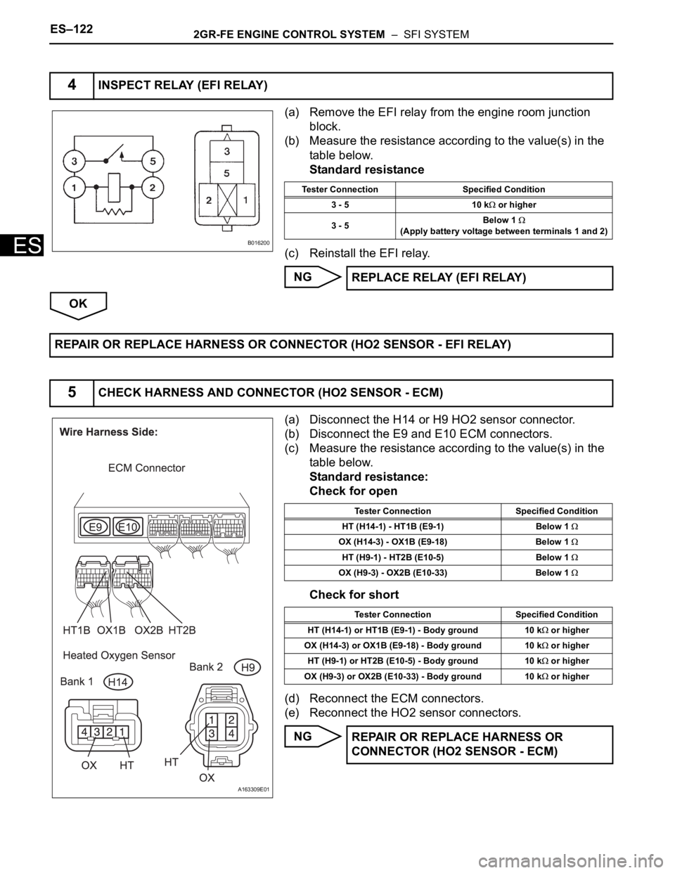
(a) Remove the EFI relay from the engine room junction
block.
(b) Measure the resistance according to the value(s) in the
table below.
Standard resistance
(c) Reinstall the EFI relay.
NG
OK
(a) Disconnect the H14 or H9 HO2 sensor connector.
(b) Disconnect the E9 and E10 ECM connectors.
(c) Measure the resistance according to the value(s) in the
table below.
Standard resistance:
Check for open
Check for short
(d) Reconnect the ECM connectors.
(e) Reconnect the HO2 sensor connectors.
NG
4INSPECT RELAY (EFI RELAY)
B016200
Tester Connection Specified Condition
3 - 5 10 k
or higher
3 - 5Below 1
(Apply battery voltage between terminals 1 and 2)
REPLACE RELAY (EFI RELAY)
REPAIR OR REPLACE HARNESS OR CONNECTOR (HO2 SENSOR - EFI RELAY)
5CHECK HARNESS AND CONNECTOR (HO2 SENSOR - ECM)
A163309E01
Tester Connection Specified Condition
HT (H14-1) - HT1B (E9-1) Below 1
OX (H14-3) - OX1B (E9-18) Below 1
HT (H9-1) - HT2B (E10-5) Below 1
OX (H9-3) - OX2B (E10-33) Below 1
Tester Connection Specified Condition
HT (H14-1) or HT1B (E9-1) - Body ground 10 k
or higher
OX (H14-3) or OX1B (E9-18) - Body ground 10 k
or higher
HT (H9-1) or HT2B (E10-5) - Body ground 10 k
or higher
OX (H9-3) or OX2B (E10-33) - Body ground 10 k
or higher
REPAIR OR REPLACE HARNESS OR
CONNECTOR (HO2 SENSOR - ECM)