2007 TOYOTA SIENNA check engine
[x] Cancel search: check enginePage 454 of 3000

ES–1482GR-FE ENGINE CONTROL SYSTEM – SFI SYSTEM
ES
TYPICAL ENABLING CONDITIONS
All:
ECT sensor cold start monitor:
ECT sensor soak monitor:
TYPICAL MALFUNCTION THRESHOLDS
ECT sensor cold start monitor:
ECT sensor soak monitor:
COMPONENT OPERATING RANGE
INSPECTION PROCEDURE
HINT:
• If any of DTC P0115, P0117, P0118 or P0125 are set simultaneously with DTC P0116, the ECT sensor
may have an open or a short circuit. Troubleshoot those DTCs first.
• Read freeze frame data using the intelligent tester. The ECM records vehicle and driving condition
information as freeze frame data the moment a DTC is stored. When troubleshooting, freeze frame
data can be helpful in determining whether the vehicle was running or stopped, whether the engine
was warmed up or not, whether the air-fuel ratio was lean or rich, as well as other data recorded at the
time of a malfunction.
(a) Connect the intelligent tester to the DLC3.
(b) Turn the ignition switch to the ON position.
(c) Turn the tester on.
(d) Enter the following menus: DIAGNOSIS / ENHANCED II
/ DTC INFO / CURRENT CODES.
(e) Read the DTC.
Monitor will run whenever these DTCs are not present. P0100, P0102, P0103 (MAF Sensor)
Battery voltage 10.5 V or more
Time after engine start 1 second or more
ECT at engine start Less than 60
C (140F)
IAT sensor circuit OK
Soak time 5 hours or more
Accumulated MAF 1421.2 g or more
Engine Running
Fuel cut OFF
Difference between ECT at engine start and IAT Less than 40
C (72F)
Battery voltage 10.5 V or more
Engine Running
Soak time 5 hours or more
ECT at engine start 60
C (140F) or more
Accumulated MAF 3298.1 g or more
ECT sensor value change Less than 5
C (9F)
ECT sensor value change Less than 5
C (9F)
Engine coolant temperature Varies with actual engine coolant temperature
1CHECK ANY OTHER DTCS OUTPUT (IN ADDITION TO DTC P0166)
Page 455 of 3000

2GR-FE ENGINE CONTROL SYSTEM – SFI SYSTEMES–149
ES
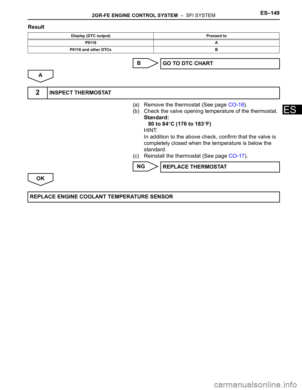
Result
B
A
(a) Remove the thermostat (See page CO-16).
(b) Check the valve opening temperature of the thermostat.
Standard:
80 to 84
C (176 to 183F)
HINT:
In addition to the above check, confirm that the valve is
completely closed when the temperature is below the
standard.
(c) Reinstall the thermostat (See page CO-17).
NG
OK
Display (DTC output) Proceed to
P0116 A
P0116 and other DTCs B
GO TO DTC CHART
2INSPECT THERMOSTAT
REPLACE THERMOSTAT
REPLACE ENGINE COOLANT TEMPERATURE SENSOR
Page 457 of 3000

2GR-FE ENGINE CONTROL SYSTEM – SFI SYSTEMES–151
ES
MONITOR STRATEGY
TYPICAL ENABLING CONDITIONS
TYPICAL MALFUNCTION THRESHOLDS
INSPECTION PROCEDURE
(a) Connect the intelligent tester to the DLC3.
(b) Turn the ignition switch to the ON position.
(c) Turn the tester on.
(d) Enter the following menus: DIAGNOSIS / ENHANCED
OBD ll / DTC INFO / CURRENT CODES.
(e) Read the DTCs.
Result
HINT:
If any DTCs other than P011B are output, troubleshoot
those DTCs first.
B
A
Related DTCs P011B: ECT / IAT sensor correlation
Required Sensors / Components (Main) ECT / IAT sensor
Required Sensors / Components (Related) -
Frequency of Operation Continuous
Duration 2 driving cycles
MIL Operation 2 driving cycles
Sequence of Operation None
The monitor will run whenever these DTCs are not present None
All of following conditions is met Condition 1 and 2
1. All of following conditions is met Condition (a), (b), (c) and (d)
(a) After ignition switch ON and engine not running time More than 20 seconds
(b) Soak Time 7 hours or more
(c) Battery voltage 10.5 V or more
(d) Time after engine start 37.5 seconds or more
2. Either of the following conditions are met Condition (a) and (b)
(a) After engine start minimum IAT -10
C (14F) or more
(b) Before engine start ECT -10
C (14F) or more
Deviated ECT minus Deviated IAT Less than -20
C (-36F) or more than 20C (36F)
1CHECK ANY OTHER DTCS OUTPUT (IN ADDITION P011B)
Display (DTC Output) Proceed to
P011BA
P011B and other DTCsB
GO TO DTC CHART
Page 458 of 3000

ES–1522GR-FE ENGINE CONTROL SYSTEM – SFI SYSTEM
ES
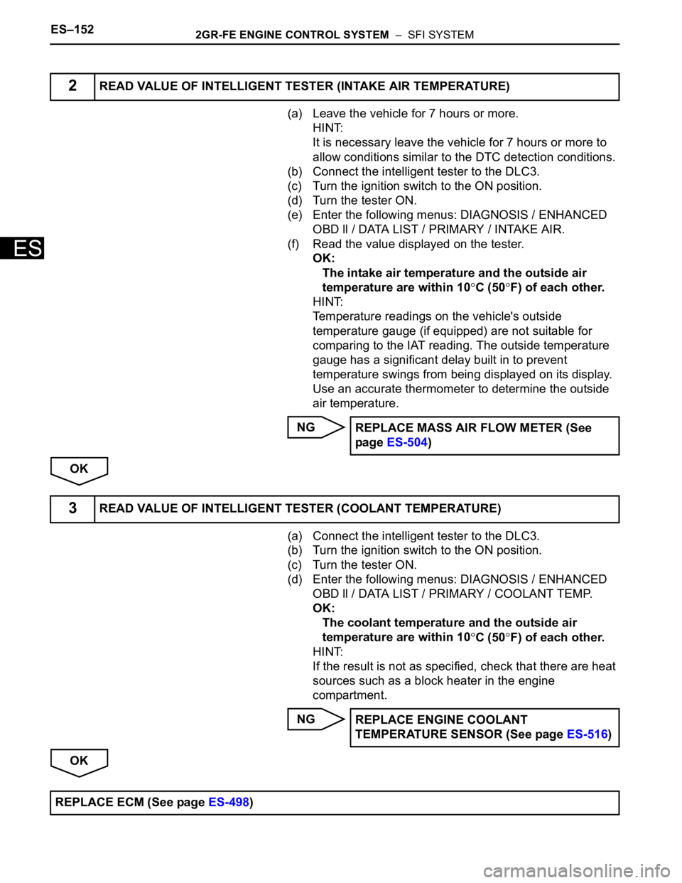
(a) Leave the vehicle for 7 hours or more.
HINT:
It is necessary leave the vehicle for 7 hours or more to
allow conditions similar to the DTC detection conditions.
(b) Connect the intelligent tester to the DLC3.
(c) Turn the ignition switch to the ON position.
(d) Turn the tester ON.
(e) Enter the following menus: DIAGNOSIS / ENHANCED
OBD ll / DATA LIST / PRIMARY / INTAKE AIR.
(f) Read the value displayed on the tester.
OK:
The intake air temperature and the outside air
temperature are within 10
C (50F) of each other.
HINT:
Temperature readings on the vehicle's outside
temperature gauge (if equipped) are not suitable for
comparing to the IAT reading. The outside temperature
gauge has a significant delay built in to prevent
temperature swings from being displayed on its display.
Use an accurate thermometer to determine the outside
air temperature.
NG
OK
(a) Connect the intelligent tester to the DLC3.
(b) Turn the ignition switch to the ON position.
(c) Turn the tester ON.
(d) Enter the following menus: DIAGNOSIS / ENHANCED
OBD ll / DATA LIST / PRIMARY / COOLANT TEMP.
OK:
The coolant temperature and the outside air
temperature are within 10
C (50F) of each other.
HINT:
If the result is not as specified, check that there are heat
sources such as a block heater in the engine
compartment.
NG
OK
2READ VALUE OF INTELLIGENT TESTER (INTAKE AIR TEMPERATURE)
REPLACE MASS AIR FLOW METER (See
page ES-504)
3READ VALUE OF INTELLIGENT TESTER (COOLANT TEMPERATURE)
REPLACE ENGINE COOLANT
TEMPERATURE SENSOR (See page ES-516)
REPLACE ECM (See page ES-498)
Page 461 of 3000

2GR-FE ENGINE CONTROL SYSTEM – SFI SYSTEMES–155
ESHINT:
• When any of these DTCs are set, check the throttle valve opening angle by selecting the following
menu items on the intelligent tester: DIAGNOSIS / ENHANCED OBD II / DATA LIST / ETCS /
THROTTLE POS AND THROTTLE POS #2.
• THROTTLE POS denotes the VTA1 signal (expressed in percentages), and THROTTLE POS #2
denotes the VTA2 signal (expressed in voltages).
Reference (Normal Condition)
MONITOR DESCRIPTION
The ECM uses the Throttle Position (TP) sensor to monitor the throttle valve opening angle. There are
several checks that the ECM performs to confirm the proper operation of the TP sensor.
• A specific voltage difference is expected between the sensor terminals, VTA1 and VTA2, for each
throttle valve opening angle. If the difference between VTA1 and VTA2 is incorrect, the ECM interprets
this as a malfunction in the sensor, and sets a DTC.
• VTA1 and VTA2 each have a specific voltage range. If VTA1 or VTA2 is outside the normal operating
range, the ECM interprets this as a malfunction in the sensor, and sets a DTC.
• VTA1 and VTA2 should never be close to the same voltage level. If VTA1 is within 0.02 V of VTA2, the
ECM determines that there is a short circuit in the sensor, and sets a DTC.
If the malfunction is not repaired successfully, a DTC is set 2 seconds after the engine is next started.
MONITOR STRATEGY
P0222Output voltage of VTA2 is 1.75 V or less for 2 seconds
(1 trip detection logic)• TP sensor (built into throttle body)
• Short in VTA2 circuit
• Open in VC circuit
•ECM
P0223Output voltage of VTA2 is 4.8 V or more, and VTA1 is
between 0.2 V and 2.02 V, for 2 seconds (1 trip
detection logic)• TP sensor (built into throttle body)
• Open in VTA2 circuit
• Open in E2 circuit
• Short between VC and VTA2 circuits
•ECM
P2135Either condition (a) or (b) is met (1 trip detection logic):
(a) Difference between output voltages of VTA1 and
VTA2 is 0.02 V or less for 0.5 seconds or more
(b) Output voltage of VTA1 is 0.2 V or less, and VTA2 is
0.5 V or less, for 0.4 seconds or more• Short between VTA1 and VTA2 circuits
• TP sensor (built into throttle body)
•ECM
Tester Display Accelerator Pedal Fully Released Accelerator Pedal Fully Depressed
THROTTLE POS 10 to 24% 64 to 96%
THROTTLE POS #2 2.1 to 3.1 V 4.5 to 5.0 V
Related DTCsP0120: Throttle position sensor 1 range check (Fluctuating)
P0122: Throttle position sensor 1 range check (Low voltage)
P0123: Throttle position sensor 1 range check (High voltage)
P0220: Throttle position sensor 2 range check (Fluctuating)
P0222: Throttle position sensor 2 range check (Low voltage)
P0223: Throttle position sensor 2 range check (High voltage)
P2135: Throttle position sensor range check (Correlation)
Required Sensors / Components (Main) Throttle position sensor
Required Sensors / Components (Related) -
Frequency of Operation Continuous
Duration2 seconds: P0120, P0122, P0123, P0220, P0222 and P0223 (Accelerator pedal ON)
10 seconds: P0120, P0122, P0123, P0220, P0222 and P0223 (Accelerator pedal
OFF)
0.5 seconds: P2135
MIL Operation Immediate
Sequence of Operation NoneDTC No. DTC Detection Condition Trouble Area
Page 463 of 3000

2GR-FE ENGINE CONTROL SYSTEM – SFI SYSTEMES–157
ES
WIRING DIAGRAM
INSPECTION PROCEDURE
HINT:
• If other DTCs relating to different systems that have terminal E2 as the ground terminal are output
simultaneously, terminal E2 may have an open circuit.
• Read freeze frame data using the intelligent tester. The ECM records vehicle and driving condition
information as freeze frame data the moment a DTC is stored. When troubleshooting, freeze frame
data can be helpful in determining whether the vehicle was running or stopped, whether the engine
was warmed up or not, whether the air-fuel ratio was lean or rich, as well as other data recorded at the
time of a malfunction.
(a) Connect the intelligent tester to the DLC3.
(b) Turn the ignition switch to the ON position and turn the
intelligent tester on.
(c) Select the following menu items: DIAGNOSIS /
ENHANCED OBD II / DATA LIST / ETCS / THROTTLE
POS and THROTTLE POS #2.
(d) Check the values displayed on the tester.
Result
1READ VALUE OF INTELLIGENT TESTER (THROTTLE POS AND THROTTLE POS #2)
A085458E27
TP#1 (VTA1)
When AP ReleasedTP#2 (VTA2)
When AP ReleasedTP#1 (VTA1)
When AP
DepressedTP#2 (VTA2)
When AP
DepressedTrouble Area Proceed to
0%Between 0 V and 0.2
V0%Between 0 V and 0.2
VVC circuit open A
100%Between 4.5 V and
5.0 V100 %Between 4.5 V and
5.0 VE2 circuit open A
0% or 100%Between 2.1 V and
3.1 V
(Fail-safe)0% or 100%Between 2.1 V and
3.1 V
(Fail-safe)VTA1 circuit open or
ground shortA
Page 464 of 3000

ES–1582GR-FE ENGINE CONTROL SYSTEM – SFI SYSTEM
ES
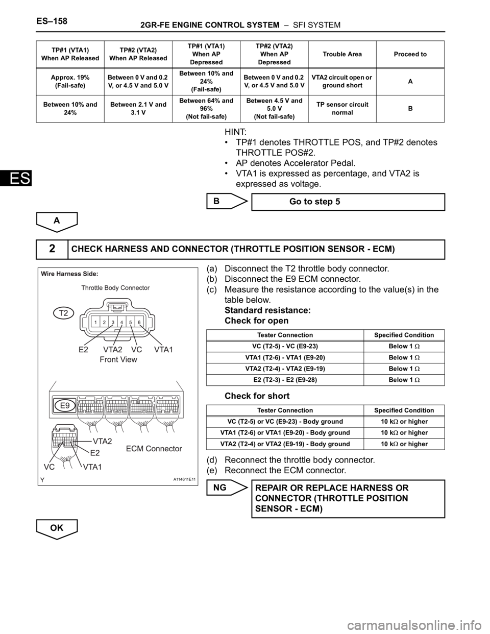
HINT:
• TP#1 denotes THROTTLE POS, and TP#2 denotes
THROTTLE POS#2.
• AP denotes Accelerator Pedal.
• VTA1 is expressed as percentage, and VTA2 is
expressed as voltage.
B
A
(a) Disconnect the T2 throttle body connector.
(b) Disconnect the E9 ECM connector.
(c) Measure the resistance according to the value(s) in the
table below.
Standard resistance:
Check for open
Check for short
(d) Reconnect the throttle body connector.
(e) Reconnect the ECM connector.
NG
OK
Approx. 19%
(Fail-safe)Between 0 V and 0.2
V, or 4.5 V and 5.0 VBetween 10% and
24%
(Fail-safe)B e t w e e n 0 V a n d 0 . 2
V, or 4.5 V and 5.0 VVTA2 circuit open or
ground shortA
Between 10% and
24%Between 2.1 V and
3.1 VBetween 64% and
96%
(Not fail-safe)Between 4.5 V and
5.0 V
(Not fail-safe)TP sensor circuit
normalB TP#1 (VTA1)
When AP ReleasedTP#2 (VTA2)
When AP ReleasedTP#1 (VTA1)
When AP
DepressedTP#2 (VTA2)
When AP
DepressedTrouble Area Proceed to
Go to step 5
2CHECK HARNESS AND CONNECTOR (THROTTLE POSITION SENSOR - ECM)
A114611E11
Tester Connection Specified Condition
VC (T2-5) - VC (E9-23) Below 1
VTA1 (T2-6) - VTA1 (E9-20) Below 1
VTA2 (T2-4) - VTA2 (E9-19) Below 1
E2 (T2-3) - E2 (E9-28) Below 1
Tester Connection Specified Condition
VC (T2-5) or VC (E9-23) - Body ground 10 k
or higher
VTA1 (T2-6) or VTA1 (E9-20) - Body ground 10 k
or higher
VTA2 (T2-4) or VTA2 (E9-19) - Body ground 10 k
or higher
REPAIR OR REPLACE HARNESS OR
CONNECTOR (THROTTLE POSITION
SENSOR - ECM)
Page 465 of 3000

2GR-FE ENGINE CONTROL SYSTEM – SFI SYSTEMES–159
ES
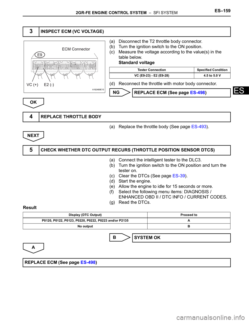
(a) Disconnect the T2 throttle body connector.
(b) Turn the ignition switch to the ON position.
(c) Measure the voltage according to the value(s) in the
table below.
Standard voltage
(d) Reconnect the throttle with motor body connector.
NG
OK
(a) Replace the throttle body (See page ES-493).
NEXT
(a) Connect the intelligent tester to the DLC3.
(b) Turn the ignition switch to the ON position and turn the
tester on.
(c) Clear the DTCs (See page ES-39).
(d) Start the engine.
(e) Allow the engine to idle for 15 seconds or more.
(f) Select the following menu items: DIAGNOSIS /
ENHANCED OBD II / DTC INFO / CURRENT CODES.
(g) Read the DTCs.
Result
B
A
3INSPECT ECM (VC VOLTAGE)
A162489E15
Tester Connection Specified Condition
VC (E9-23) - E2 (E9-28) 4.5 to 5.0 V
REPLACE ECM (See page ES-498)
4REPLACE THROTTLE BODY
5CHECK WHETHER DTC OUTPUT RECURS (THROTTLE POSITION SENSOR DTCS)
Display (DTC Output) Proceed to
P0120, P0122, P0123, P0220, P0222, P0223 and/or P2135 A
No output B
SYSTEM OK
REPLACE ECM (See page ES-498)