Page 482 of 3000
ES–1762GR-FE ENGINE CONTROL SYSTEM – SFI SYSTEM
ES
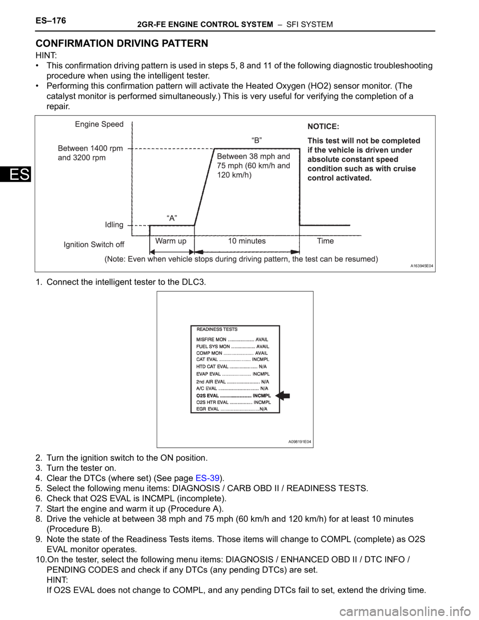
CONFIRMATION DRIVING PATTERN
HINT:
• This confirmation driving pattern is used in steps 5, 8 and 11 of the following diagnostic troubleshooting
procedure when using the intelligent tester.
• Performing this confirmation pattern will activate the Heated Oxygen (HO2) sensor monitor. (The
catalyst monitor is performed simultaneously.) This is very useful for verifying the completion of a
repair.
1. Connect the intelligent tester to the DLC3.
2. Turn the ignition switch to the ON position.
3. Turn the tester on.
4. Clear the DTCs (where set) (See page ES-39).
5. Select the following menu items: DIAGNOSIS / CARB OBD II / READINESS TESTS.
6. Check that O2S EVAL is INCMPL (incomplete).
7. Start the engine and warm it up (Procedure A).
8. Drive the vehicle at between 38 mph and 75 mph (60 km/h and 120 km/h) for at least 10 minutes
(Procedure B).
9. Note the state of the Readiness Tests items. Those items will change to COMPL (complete) as O2S
EVAL monitor operates.
10.On the tester, select the following menu items: DIAGNOSIS / ENHANCED OBD II / DTC INFO /
PENDING CODES and check if any DTCs (any pending DTCs) are set.
HINT:
If O2S EVAL does not change to COMPL, and any pending DTCs fail to set, extend the driving time.
A163945E04
A098191E04
Page 484 of 3000
ES–1782GR-FE ENGINE CONTROL SYSTEM – SFI SYSTEM
ES
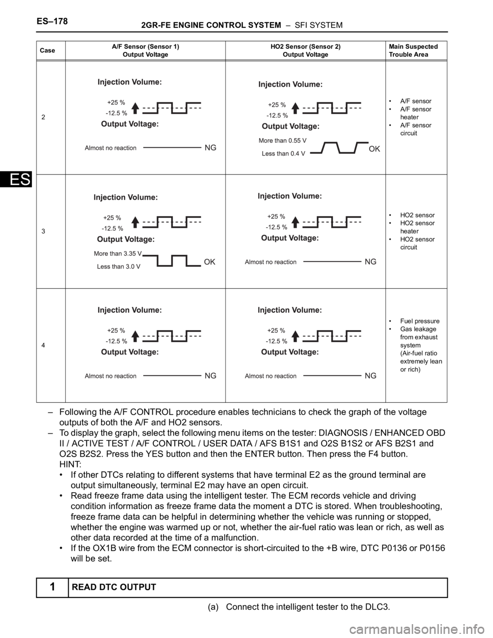
– Following the A/F CONTROL procedure enables technicians to check the graph of the voltage
outputs of both the A/F and HO2 sensors.
– To display the graph, select the following menu items on the tester: DIAGNOSIS / ENHANCED OBD
II / ACTIVE TEST / A/F CONTROL / USER DATA / AFS B1S1 and O2S B1S2 or AFS B2S1 and
O2S B2S2. Press the YES button and then the ENTER button. Then press the F4 button.
HINT:
• If other DTCs relating to different systems that have terminal E2 as the ground terminal are
output simultaneously, terminal E2 may have an open circuit.
• Read freeze frame data using the intelligent tester. The ECM records vehicle and driving
condition information as freeze frame data the moment a DTC is stored. When troubleshooting,
freeze frame data can be helpful in determining whether the vehicle was running or stopped,
whether the engine was warmed up or not, whether the air-fuel ratio was lean or rich, as well as
other data recorded at the time of a malfunction.
• If the OX1B wire from the ECM connector is short-circuited to the +B wire, DTC P0136 or P0156
will be set.
(a) Connect the intelligent tester to the DLC3.
2• A/F sensor
• A/F sensor
heater
• A/F sensor
circuit
3• HO2 sensor
• HO2 sensor
heater
• HO2 sensor
circuit
4•Fuel pressure
• Gas leakage
from exhaust
system
(Air-fuel ratio
extremely lean
or rich)
1READ DTC OUTPUT
CaseA/F Sensor (Sensor 1)
Output VoltageHO2 Sensor (Sensor 2)
Output VoltageMain Suspected
Trouble Area
Page 485 of 3000
2GR-FE ENGINE CONTROL SYSTEM – SFI SYSTEMES–179
ES
(b) Turn the ignition switch to the ON position and turn the
tester on.
(c) Select the following menu items: DIAGNOSIS /
ENHANCED OBD II / DTC INFO / CURRENT CODES.
(d) Read the DTCs.
Result
B
C
A
(a) Connect the intelligent tester to the DLC3.
(b) Turn the ignition switch to the ON position and turn the
tester on.
(c) Select the following menu items: DIAGNOSIS /
ENHANCED OBD II / DATA LIST / PRIMARY / O2S
B1S2 or O2S B2S2.
(d) Allow the engine to idle.
(e) Read the Heated Oxygen (HO2) sensor output voltage
while idling.
Result
B
A
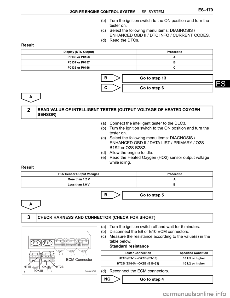
(a) Turn the ignition switch off and wait for 5 minutes.
(b) Disconnect the E9 or E10 ECM connectors.
(c) Measure the resistance according to the value(s) in the
table below.
Standard resistance
(d) Reconnect the ECM connectors.
NG
Display (DTC Output) Proceed to
P0138 or P0158 A
P0137 or P0157 B
P0136 or P0156 C
Go to step 13
Go to step 6
2READ VALUE OF INTELLIGENT TESTER (OUTPUT VOLTAGE OF HEATED OXYGEN
SENSOR)
HO2 Sensor Output Voltages Proceed to
More than 1.2 V A
Less than 1.0 V B
Go to step 5
3CHECK HARNESS AND CONNECTOR (CHECK FOR SHORT)
G035620E19
Tester Connection Specified Condition
HT1B (E9-1) - OX1B (E9-18) 10 k
or higher
HT2B (E10-5) - OX2B (E10-33) 10 k
or higher
Go to step 4
Page 486 of 3000
ES–1802GR-FE ENGINE CONTROL SYSTEM – SFI SYSTEM
ES
OK
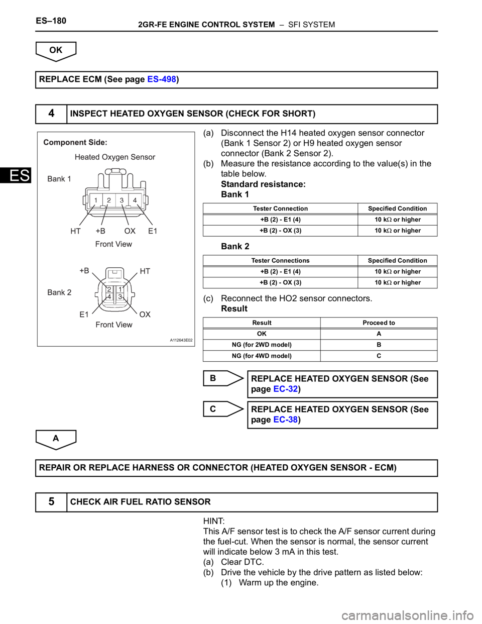
(a) Disconnect the H14 heated oxygen sensor connector
(Bank 1 Sensor 2) or H9 heated oxygen sensor
connector (Bank 2 Sensor 2).
(b) Measure the resistance according to the value(s) in the
table below.
Standard resistance:
Bank 1
Bank 2
(c) Reconnect the HO2 sensor connectors.
Result
B
C
A
HINT:
This A/F sensor test is to check the A/F sensor current during
the fuel-cut. When the sensor is normal, the sensor current
will indicate below 3 mA in this test.
(a) Clear DTC.
(b) Drive the vehicle by the drive pattern as listed below:
(1) Warm up the engine. REPLACE ECM (See page ES-498)
4INSPECT HEATED OXYGEN SENSOR (CHECK FOR SHORT)
A112643E02
Tester Connection Specified Condition
+B (2) - E1 (4) 10 k
or higher
+B (2) - OX (3) 10 k
or higher
Tester Connections Specified Condition
+B (2) - E1 (4) 10 k
or higher
+B (2) - OX (3) 10 k
or higher
Result Proceed to
OK A
NG (for 2WD model) B
NG (for 4WD model) C
REPLACE HEATED OXYGEN SENSOR (See
page EC-32)
REPLACE HEATED OXYGEN SENSOR (See
page EC-38)
REPAIR OR REPLACE HARNESS OR CONNECTOR (HEATED OXYGEN SENSOR - ECM)
5CHECK AIR FUEL RATIO SENSOR
Page 488 of 3000
ES–1822GR-FE ENGINE CONTROL SYSTEM – SFI SYSTEM
ES
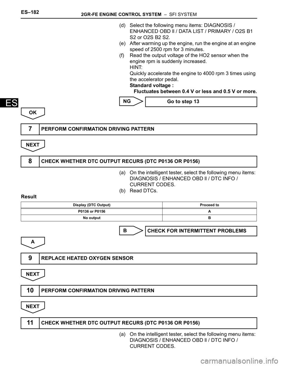
(d) Select the following menu items: DIAGNOSIS /
ENHANCED OBD ll / DATA LIST / PRIMARY / O2S B1
S2 or O2S B2 S2.
(e) After warming up the engine, run the engine at an engine
speed of 2500 rpm for 3 minutes.
(f) Read the output voltage of the HO2 sensor when the
engine rpm is suddenly increased.
HINT:
Quickly accelerate the engine to 4000 rpm 3 times using
the accelerator pedal.
Standard voltage :
Fluctuates between 0.4 V or less and 0.5 V or more.
NG
OK
NEXT
(a) On the intelligent tester, select the following menu items:
DIAGNOSIS / ENHANCED OBD ll / DTC INFO /
CURRENT CODES.
(b) Read DTCs.
Result
B
A
NEXT
NEXT
(a) On the intelligent tester, select the following menu items:
DIAGNOSIS / ENHANCED OBD ll / DTC INFO /
CURRENT CODES. Go to step 13
7PERFORM CONFIRMATION DRIVING PATTERN
8CHECK WHETHER DTC OUTPUT RECURS (DTC P0136 OR P0156)
Display (DTC Output) Proceed to
P0136 or P0156 A
No output B
CHECK FOR INTERMITTENT PROBLEMS
9REPLACE HEATED OXYGEN SENSOR
10PERFORM CONFIRMATION DRIVING PATTERN
11CHECK WHETHER DTC OUTPUT RECURS (DTC P0136 OR P0156)
Page 490 of 3000
ES–1842GR-FE ENGINE CONTROL SYSTEM – SFI SYSTEM
ES
Result
B
C
A
OK:
No gas leakage.
NG
OK
A087979E15
Result Proceed to
OK A
NG (for 2WD model) B
NG (for 4WD model) C
REPLACE AIR FUEL RATIO SENSOR (See
page EC-19)
REPLACE AIR FUEL RATIO SENSOR (See
page EC-26)
CHECK AND REPLACE EXTREMELY RICH OR LEAN ACTUAL AIR FUEL RATIO (INJECTOR,
FUEL PRESSURE, GAS LEAKAGE FROM EXHAUST SYSTEM)
13INSPECT FOR EXHAUST GAS LEAK
REPAIR OR REPLACE EXHAUST GAS
LEAKAGE POINT
Page 492 of 3000
ES–1862GR-FE ENGINE CONTROL SYSTEM – SFI SYSTEM
ES
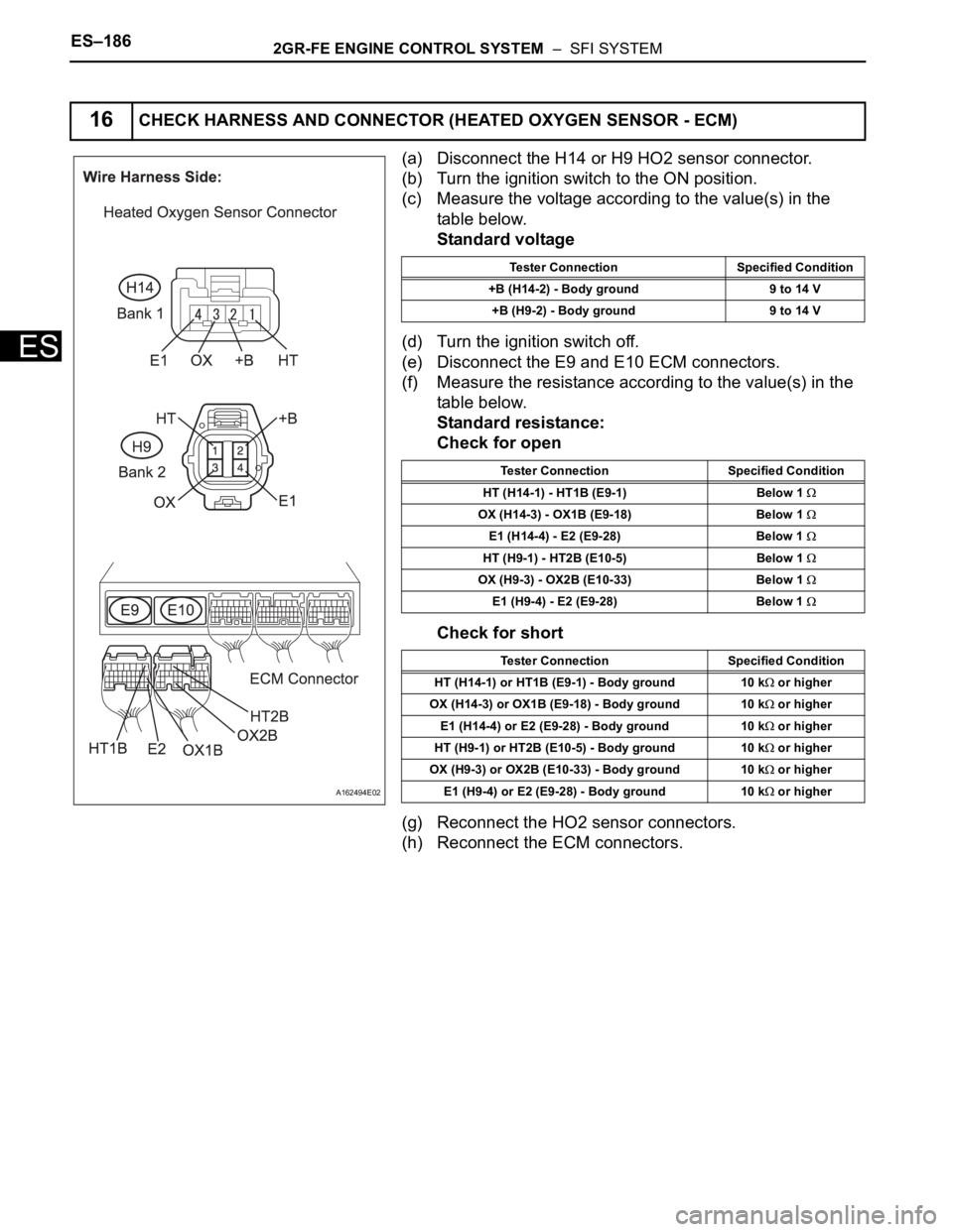
(a) Disconnect the H14 or H9 HO2 sensor connector.
(b) Turn the ignition switch to the ON position.
(c) Measure the voltage according to the value(s) in the
table below.
Standard voltage
(d) Turn the ignition switch off.
(e) Disconnect the E9 and E10 ECM connectors.
(f) Measure the resistance according to the value(s) in the
table below.
Standard resistance:
Check for open
Check for short
(g) Reconnect the HO2 sensor connectors.
(h) Reconnect the ECM connectors.
16CHECK HARNESS AND CONNECTOR (HEATED OXYGEN SENSOR - ECM)
A162494E02
Tester Connection Specified Condition
+B (H14-2) - Body ground 9 to 14 V
+B (H9-2) - Body ground 9 to 14 V
Tester Connection Specified Condition
HT (H14-1) - HT1B (E9-1) Below 1
OX (H14-3) - OX1B (E9-18) Below 1
E1 (H14-4) - E2 (E9-28) Below 1
HT (H9-1) - HT2B (E10-5) Below 1
OX (H9-3) - OX2B (E10-33) Below 1
E1 (H9-4) - E2 (E9-28) Below 1
Tester Connection Specified Condition
HT (H14-1) or HT1B (E9-1) - Body ground 10 k
or higher
OX (H14-3) or OX1B (E9-18) - Body ground 10 k
or higher
E1 (H14-4) or E2 (E9-28) - Body ground 10 k
or higher
HT (H9-1) or HT2B (E10-5) - Body ground 10 k
or higher
OX (H9-3) or OX2B (E10-33) - Body ground 10 k
or higher
E1 (H9-4) or E2 (E9-28) - Body ground 10 k
or higher
Page 498 of 3000
ES–1922GR-FE ENGINE CONTROL SYSTEM – SFI SYSTEM
ES
– Following the A/F CONTROL procedure enables technicians to check and graph the voltage outputs
of both the A/F and HO2 sensors.
– To display the graph, select the following menu items on the tester: DIAGNOSIS / ENHANCED OBD
II / ACTIVE TEST / A/F CONTROL / USER DATA / AFS B1S1 and O2S B1S2 or AFS B2S1 and
O2S B2S2. Press the YES button and then the ENTER button. Then press the F4 button.
HINT:
• Read freeze frame data using the intelligent tester. The ECM records vehicle and driving
condition information as freeze frame data the moment a DTC is stored. When troubleshooting,
freeze frame data can be helpful in determining whether the vehicle was running or stopped,
whether the engine was warmed up or not, whether the air-fuel ratio was lean or rich, as well as
other data recorded at the time of a malfunction.
• A low A/F sensor voltage could be caused by a rich air-fuel mixture. Check for conditions that
would cause the engine to run rich.
• A high A/F sensor voltage could be caused by a lean air-fuel mixture. Check for conditions that
would cause the engine to run lean.
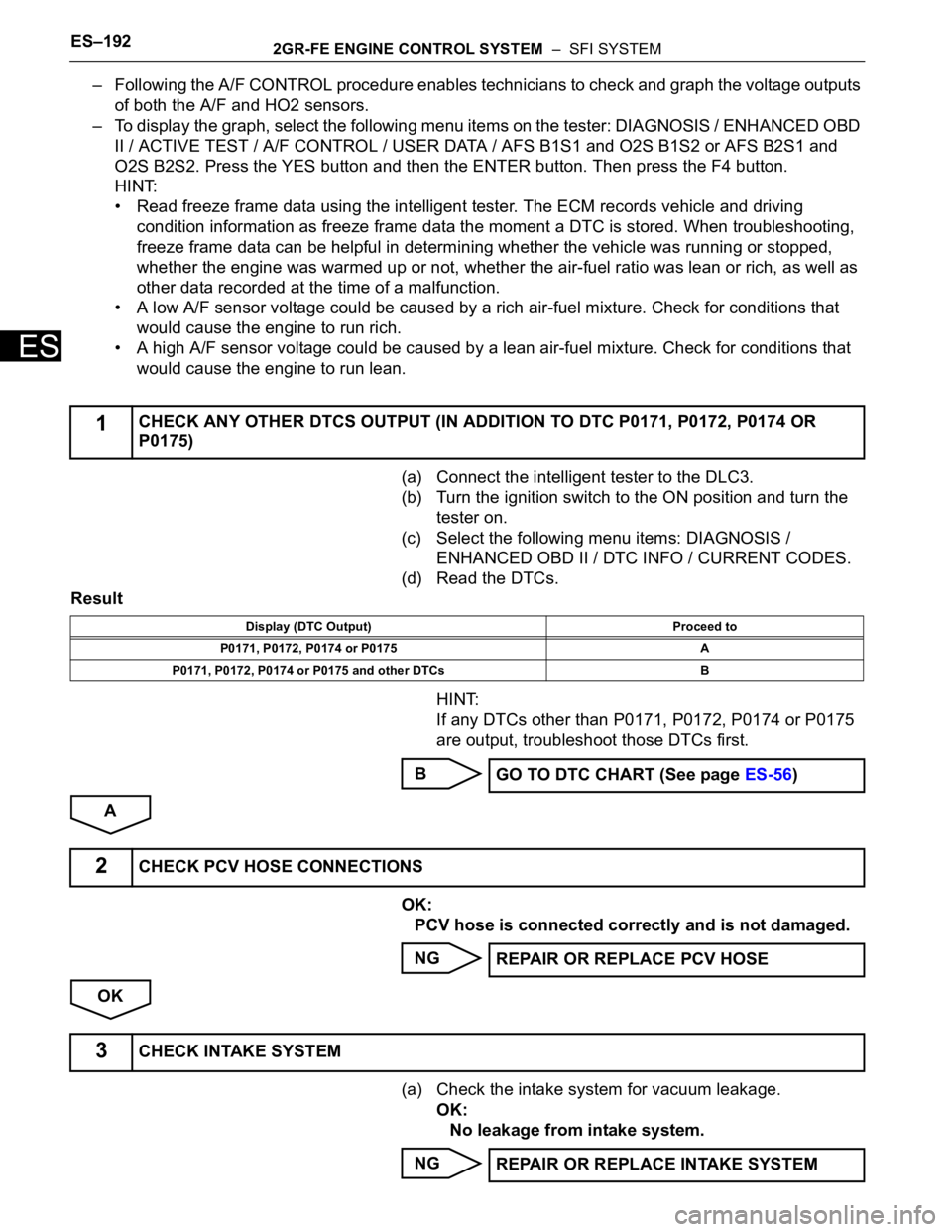
(a) Connect the intelligent tester to the DLC3.
(b) Turn the ignition switch to the ON position and turn the
tester on.
(c) Select the following menu items: DIAGNOSIS /
ENHANCED OBD II / DTC INFO / CURRENT CODES.
(d) Read the DTCs.
Result
HINT:
If any DTCs other than P0171, P0172, P0174 or P0175
are output, troubleshoot those DTCs first.
B
A
OK:
PCV hose is connected correctly and is not damaged.
NG
OK
(a) Check the intake system for vacuum leakage.
OK:
No leakage from intake system.
NG
1CHECK ANY OTHER DTCS OUTPUT (IN ADDITION TO DTC P0171, P0172, P0174 OR
P0175)
Display (DTC Output) Proceed to
P0171, P0172, P0174 or P0175 A
P0171, P0172, P0174 or P0175 and other DTCs B
GO TO DTC CHART (See page ES-56)
2CHECK PCV HOSE CONNECTIONS
REPAIR OR REPLACE PCV HOSE
3CHECK INTAKE SYSTEM
REPAIR OR REPLACE INTAKE SYSTEM