Page 2792 of 3000
AIR CONDITIONING – AIR CONDITIONING SYSTEM (for Automatic Air Conditioning Sys-
tem)AC–49
AC
Result
B
A
(a) Use the intelligent tester to check if the multiplex
communication system (BEAN) is functioning normally.
Result
B
A
(a) Remove the A/C amplifier with the connectors still
connected.
(b) Measure the waveform of the connector.
Result Proceed to
CAN DTC is not output A
CAN DTC is output B
GO TO CAN COMMUNICATION SYSTEM
2CHECK MULTIPLEX COMMUNICATION SYSTEM
Result Proceed to
BEAN DTC is not output A
BEAN DTC is output B
GO TO MULTIPLEX COMMUNICATION
SYSTEM
3INSPECT A/C AMPLIFIER
E145185E01
E116941E03
Item Contents
Tool setting 200 mV/DIV., 10 ms./DIV.
Vehicle conditionEngine is running
A/C switch: ON
Blower switch: LO
Page 2805 of 3000

AC–62AIR CONDITIONING – AIR CONDITIONING SYSTEM (for Automatic Air Conditioning Sys-
tem)
AC
OK
(a) Use a refrigerant recovery unit to recover refrigerant.
(b) Evacuate the A/C system.
(c) Add an appropriate amount of refrigerant (See page AC-
173).
HINT:
If refrigerant is added and the system has not been
properly evacuated (insufficient vacuum time), moisture
in the air remaining in the system will freeze in the
expansion valve, blocking the flow on the high pressure
side. Therefore, in order to confirm the problem, recover
the refrigerant and properly evacuate the system. Add an
appropriate amount of refrigerant, and check for the
DTC.
NEXT
(a) Recheck for the DTC when the following conditions are
satisfied.
NOTICE:
If refrigerant pressure on the high pressure side
becomes high, the DTC will be set. It is necessary to
measure the voltage for a certain amount of time
(approximately 10 minutes) because the DTC may be
set after the A/C operates for a while.
HINT:
• When the outside air temperature is low (below -1.5
C
(29.3
F)), the compressor stops due to operation of
the ambient temperature sensor and the evaporator
temperature sensor to prevent the evaporator from
freezing. In this case, perform the inspection in a
warm indoor environment.
14CHARGE REFRIGERANT
15RECHECK DTC
Item Condition
Vehicle Doors Fully open
Temperature Setting MAX COLD
Blower Speed HI
A/C Switch ON
R/F Switch RECIRCULATION
Interior Temperature 25 to 35
C (77 to 95F)
Engine Speed 2000 rpm
Page 2806 of 3000

AIR CONDITIONING – AIR CONDITIONING SYSTEM (for Automatic Air Conditioning Sys-
tem)AC–63
AC
• If refrigerant is added and the system has not been
properly evacuated (insufficient vacuum time),
moisture in the air remaining in the system will freeze
in the expansion valve, blocking the flow on the high
pressure side. Therefore, in order to confirm the
problem, recover the refrigerant and properly
evacuate the system. Add an appropriate amount of
refrigerant, and check for the DTC. If the DTC is not
output after this work, it indicates that the cooler dryer
in the condenser is not able to absorb moisture in the
refrigerant cycle. In this case, it is necessary to
replace the cooler dryer in order to complete the
repair.
Result
B
A
(a) Replace the expansion valve with a normal one (See
page AC-186).
HINT:
Replace the expansion valve with a normal one because
the expansion valve is either stuck or clogged.
NEXT
(a) Add an appropriate amount of refrigerant (See page AC-
173).
NEXT
(a) Recheck for the DTC when the following conditions are
satisfied.
Result Proceed to
DTC B1423 is output A
DTC B1423 is not output B
REPLACE COOLER DRYER
16REPLACE EXPANSION VALVE
17CHARGE REFRIGERANT
18RECHECK DTC
Item Condition
Vehicle Doors Fully open
Temperature Setting MAX COLD
Blower Speed HI
A/C Switch ON
R/F Switch RECIRCULATION
Interior Temperature 25 to 35
C (77 to 95F)
Engine Speed 2000 rpm
Page 2849 of 3000
AC–106AIR CONDITIONING – AIR CONDITIONING SYSTEM (for Automatic Air Conditioning Sys-
tem)
AC
A
(a) Warm up the engine.
(b) Enter the actuator check mode (See page AC-15).
(c) Press the DEF switch and change to step operation.
(d) Press the DEF switch and check the air flow by hand.
OK:
Air outlet mode changes in accordance with each
display code.
Result
B
C
A
3PERFORM ACTUATOR CHECK
Display Code Air Flow Condition
0 FACE (0%)
1 FACE (0%)
2 FACE (0%)
3 FACE (0%)
4 FACE (0%)
5FACE/FOOT (33.5%)
6 FOOT (53.5%)
7 FOOT (53.5%)
8FACE/DEF (73.5%)
9 DEF (100%)
Result Proceed to
NGA
OK (When troubleshooting according to the PROBLEM SYMPTOMS TABLE) B
OK (When troubleshooting according to the DTC) C
PROCEED TO NEXT CIRCUIT INSPECTION
SHOWN IN PROBLEM SYMPTOMS TABLE
REPLACE A/C AMPLIFIER
Page 2864 of 3000
AIR CONDITIONING – AIR CONDITIONING SYSTEM (for Automatic Air Conditioning Sys-
tem)AC–121
AC
(a) Warm up the engine.
(b) Enter the actuator check mode (See page AC-15).
(c) Press the DEF switch and change to step operation.
(d) Press the DEF switch and check the air flow by hand.
OK:
Air outlet mode changes in accordance with each
display code.
Result
B
C
A
3PERFORM ACTUATOR CHECK
Display Code Air flow condition
0FACE1 (0%)
1FACE1 (0%)
2FACE1 (0%)
3 FACE2 (16.5%)
4 FACE/FOOT (44%)
5 FACE/FOOT (44%)
6 FACE/FOOT (44%)
7FOOT (100%)
8FOOT (100%)
9FOOT (100%)
Result Proceed to
NGA
OK (When troubleshooting according to the PROBLEM SYMPTOMS TABLE) B
OK (When troubleshooting according to the DTC) C
PROCEED TO NEXT CIRCUIT INSPECTION
SHOWN IN PROBLEM SYMPTOMS TABLE
REPLACE A/C AMPLIFIER
Page 2893 of 3000
AC–150AIR CONDITIONING – AIR CONDITIONING SYSTEM (for Automatic Air Conditioning Sys-
tem)
AC
DESCRIPTION
The main power source is supplied to the A/C amplifier when the ignition switch is turned to the ON
position.
The power source is used for operating the A/C amplifier and servo motor, etc.
WIRING DIAGRAM
INSPECTION PROCEDURE
HINT:
Start the engine before inspection. Check the IG1 relay or battery if the engine does not start.
(a) Remove the HTR fuse from the driver side junction
block.
(b) Measure the resistance according to the value(s) in the
table below.
Standard resistance
NG
IG Power Source Circuit
1INSPECT FUSE (HTR)
E130466E04
Tester Item Condition Specified Condition
HTR fuse Always Below 1
REPLACE FUSE (HTR)
Page 2903 of 3000

AC–14AIR CONDITIONING – AIR CONDITIONING SYSTEM (for Automatic Air Conditioning Sys-
tem)
AC
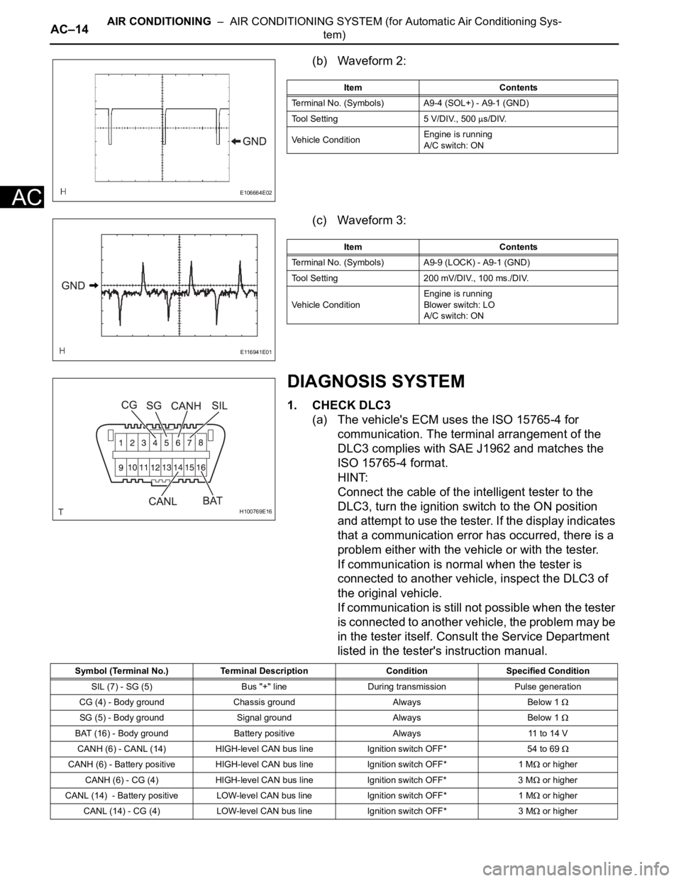
(b) Waveform 2:
(c) Waveform 3:
DIAGNOSIS SYSTEM
1. CHECK DLC3
(a) The vehicle's ECM uses the ISO 15765-4 for
communication. The terminal arrangement of the
DLC3 complies with SAE J1962 and matches the
ISO 15765-4 format.
HINT:
Connect the cable of the intelligent tester to the
DLC3, turn the ignition switch to the ON position
and attempt to use the tester. If the display indicates
that a communication error has occurred, there is a
problem either with the vehicle or with the tester.
If communication is normal when the tester is
connected to another vehicle, inspect the DLC3 of
the original vehicle.
If communication is still not possible when the tester
is connected to another vehicle, the problem may be
in the tester itself. Consult the Service Department
listed in the tester's instruction manual.
E106664E02
Item Contents
Terminal No. (Symbols) A9-4 (SOL+) - A9-1 (GND)
Tool Setting 5 V/DIV., 500
s/DIV.
Vehicle ConditionEngine is running
A/C switch: ON
E116941E01
Item Contents
Terminal No. (Symbols) A9-9 (LOCK) - A9-1 (GND)
Tool Setting 200 mV/DIV., 100 ms./DIV.
Vehicle ConditionEngine is running
Blower switch: LO
A/C switch: ON
H100769E16
Symbol (Terminal No.) Terminal Description Condition Specified Condition
SIL (7) - SG (5) Bus "+" line During transmission Pulse generation
CG (4) - Body ground Chassis ground Always Below 1
SG (5) - Body ground Signal ground Always Below 1
BAT (16) - Body ground Battery positive Always 11 to 14 V
CANH (6) - CANL (14) HIGH-level CAN bus line Ignition switch OFF*54 to 69
CANH (6) - Battery positive HIGH-level CAN bus line Ignition switch OFF* 1 M or higher
CANH (6) - CG (4) HIGH-level CAN bus line Ignition switch OFF* 3 M
or higher
CANL (14) - Battery positive LOW-level CAN bus line Ignition switch OFF* 1 M
or higher
CANL (14) - CG (4) LOW-level CAN bus line Ignition switch OFF* 3 M
or higher
Page 2904 of 3000

AIR CONDITIONING – AIR CONDITIONING SYSTEM (for Automatic Air Conditioning Sys-
tem)AC–15
AC
NOTICE:
*: Before measuring the resistance, leave the
vehicle as is for at least 1 minute and do not
operate the ignition switch, any other switches
or the doors.
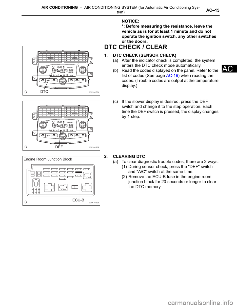
DTC CHECK / CLEAR
1. DTC CHECK (SENSOR CHECK)
(a) After the indicator check is completed, the system
enters the DTC check mode automatically.
(b) Read the codes displayed on the panel. Refer to the
list of codes (See page AC-19) when reading the
codes. (Trouble codes are output at the temperature
display.)
(c) If the slower display is desired, press the DEF
switch and change it to the step operation. Each
time the DEF switch is pressed, the display changes
by 1 step.
2. CLEARING DTC
(a) To clear diagnostic trouble codes, there are 2 ways.
(1) During sensor check, press the "DEF" switch
and "A/C" switch at the same time.
(2) Remove the ECU-B fuse in the engine room
junction block for 20 seconds or longer to clear
the DTC memory.
I035391E01
I035391E02
I035414E02