Page 2457 of 3000
BRAKE CONTROL – VEHICLE STABILITY CONTROL SYSTEMBC–95
BC
WIRING DIAGRAM
INSPECTION PROCEDURE
(a) Connect the intelligent tester to the DLC3.
(b) Start the engine.
(c) Select the DATA LIST mode on the intelligent tester.
ABS / VSC:
(d) Check that there is no difference between the speed
value output from the speed sensor displayed on the
intelligent tester and the speed value displayed on the
speedometer when driving the vehicle.
OK:
There is almost no difference from the displayed
speed value.
HINT:
There is tolerance of +- 10 % in the speedometer
indication.
NG
OK
1READ VALUE ON INTELLIGENT TESTER (FRONT SPEED SENSOR)
F040884E11
Tester Display Measurement Item/Range Normal Condition
WHEEL SPD FRWheel speed sensor (FR) reading / min.: 0
km/h (0 MPH), max.: 326 km/h (202 MPH)Actual wheel speed
WHEEL SPD FLWheel speed sensor (FL) reading / min.: 0
km/h (0 MPH), max.: 326 km/h (202 MPH)Actual wheel speed
Go to step 3
Page 2463 of 3000

BRAKE CONTROL – VEHICLE STABILITY CONTROL SYSTEMBC–101
BC
INSPECTION PROCEDURE
(a) Connect the intelligent tester to the DLC3.
(b) Start the engine.
(c) Select the DATA LIST mode on the intelligent tester.
ABS / VSC:
(d) Check that there is no difference between the speed
value output from the speed sensor displayed by the
intelligent tester and the speed value displayed on the
speedometer when driving the vehicle.
OK:
There is almost no difference in the displayed
speed value.
HINT:
There is tolerance of +- 10 % in the speedometer
indication.
NG
OK
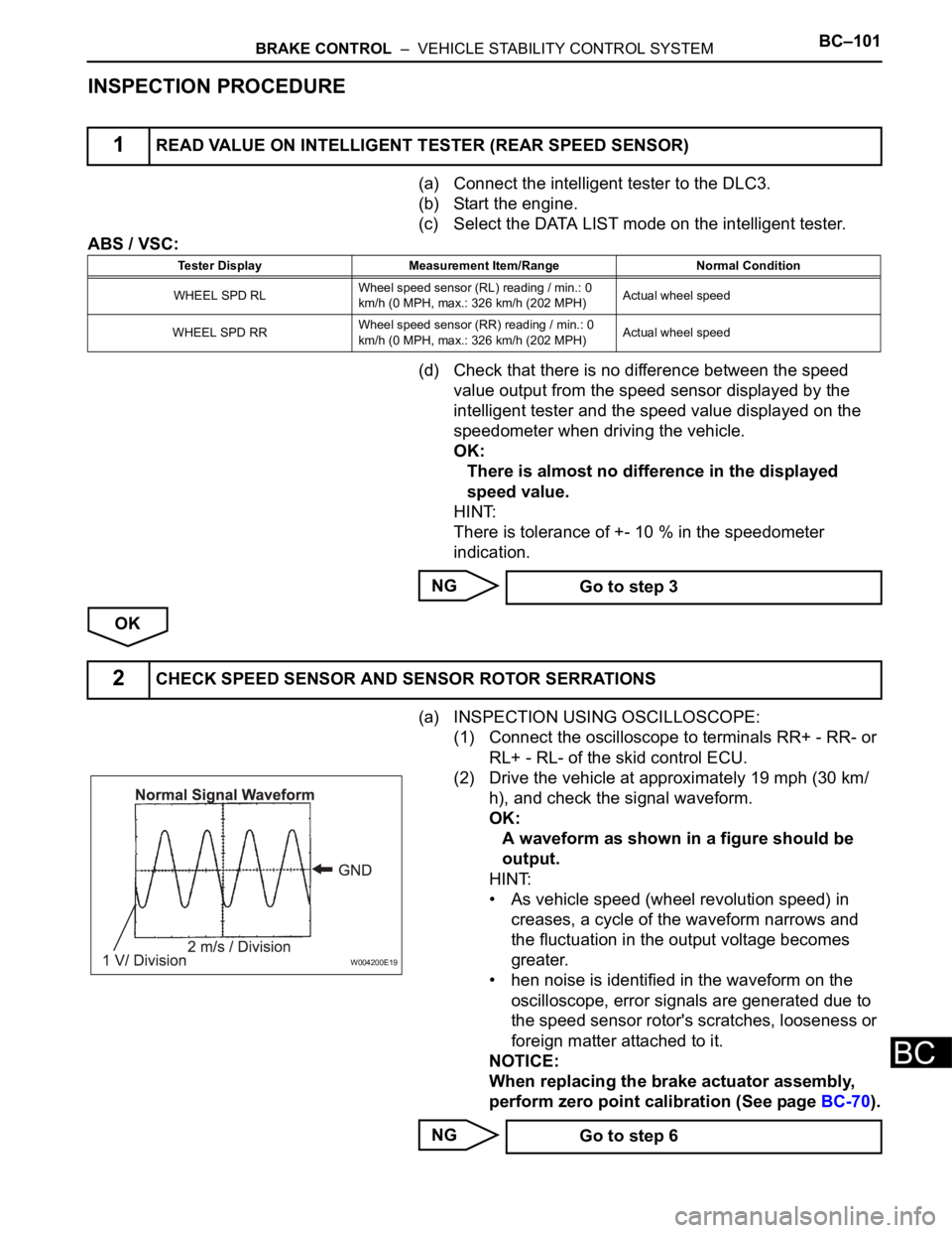
(a) INSPECTION USING OSCILLOSCOPE:
(1) Connect the oscilloscope to terminals RR+ - RR- or
RL+ - RL- of the skid control ECU.
(2) Drive the vehicle at approximately 19 mph (30 km/
h), and check the signal waveform.
OK:
A waveform as shown in a figure should be
output.
HINT:
• As vehicle speed (wheel revolution speed) in
creases, a cycle of the waveform narrows and
the fluctuation in the output voltage becomes
greater.
• hen noise is identified in the waveform on the
oscilloscope, error signals are generated due to
the speed sensor rotor's scratches, looseness or
foreign matter attached to it.
NOTICE:
When replacing the brake actuator assembly,
perform zero point calibration (See page BC-70).
NG
1READ VALUE ON INTELLIGENT TESTER (REAR SPEED SENSOR)
Tester Display Measurement Item/Range Normal Condition
WHEEL SPD RLWheel speed sensor (RL) reading / min.: 0
km/h (0 MPH, max.: 326 km/h (202 MPH)Actual wheel speed
WHEEL SPD RRWheel speed sensor (RR) reading / min.: 0
km/h (0 MPH, max.: 326 km/h (202 MPH)Actual wheel speed
Go to step 3
2CHECK SPEED SENSOR AND SENSOR ROTOR SERRATIONS
W004200E19
Go to step 6
Page 2472 of 3000
BC–110BRAKE CONTROL – VEHICLE STABILITY CONTROL SYSTEM
BC
WIRING DIAGRAM
INSPECTION PROCEDURE
(a) Connect the intelligent tester to the DLC3.
(b) Start the engine.
(c) Select the ACTIVE TEST mode on the intelligent tester.
ABS / VSC:
(d) Check the operation sound of the ABS motor individually
when operating it with the intelligent tester.
OK:
Operation sound of the ABS motor should be
heard.
NG
1PERFORM ACTIVE TEST USING INTELLIGENT TESTER (ABS MOTOR RELAY)
F045122E04
Tester Display Test Part Control Range Diagnostic Note
ABS MOT RELAY ABS motor relay Relay ON / OFFOperation of motor (clicking
sound) can be heard
Go to step 2
Page 2479 of 3000
BRAKE CONTROL – VEHICLE STABILITY CONTROL SYSTEMBC–117
BC
DESCRIPTION
If trouble occurs the engine control system, the ECM transmits the abnormality to the skid control ECU.
The skid control ECU set this DTC and the skid control ECU prohibits TRAC and VSC control.
INSPECTION PROCEDURE
(a) Check if the normal system code is recorded for engine
control system.
Result
B
A
DTC C1201/51 Engine Control System Malfunction
DTC Code DTC Detection Condition Trouble Area
C1201/51Engine control system malfunction signal continues for
5 sec. or more.Engine control system
1CHECK ENGINE CONTROL SYSTEM
Result Proceed to
DTC is not outputA
DTC is outputB
INSPECT ENGINE CONTROL SYSTEM
REPLACE ECM
Page 2480 of 3000
BC–118BRAKE CONTROL – VEHICLE STABILITY CONTROL SYSTEM
BC
DESCRIPTION
The circuit is used to send TRAC and VSC control information from the skid control ECU to the ECM, and
engine control information from the ECM to the skid control ECU through the CAN communication
system.
INSPECTION PROCEDURE
(a) Check that the proper ECM and brake actuator assembly
(skid control ECU) are installed.
OK:
Proper ECUs are installed.
NG
OK
DTC C1203/53 ECM Communication Circuit Malfunction
DTC Code DTC Detection Condition Trouble Area
C1203/53Engine, drive source and destination variations that are sent
from the ECM do not match the ones of the skid control ECU.ECM
1CHECK PART NUMBER (ECM AND BRAKE ACTUATOR ASSEMBLY)
REPLACE ECUS WITH PROPER ONES
REPLACE ECM
Page 2491 of 3000

BRAKE CONTROL – VEHICLE STABILITY CONTROL SYSTEMBC–129
BC
(b) Check continuity of the ECU-IG fuse.
Standard resistance
NG
OK
(a) Check the positive battery voltage.
Standard voltage:
11 to 14 V
NG
OK
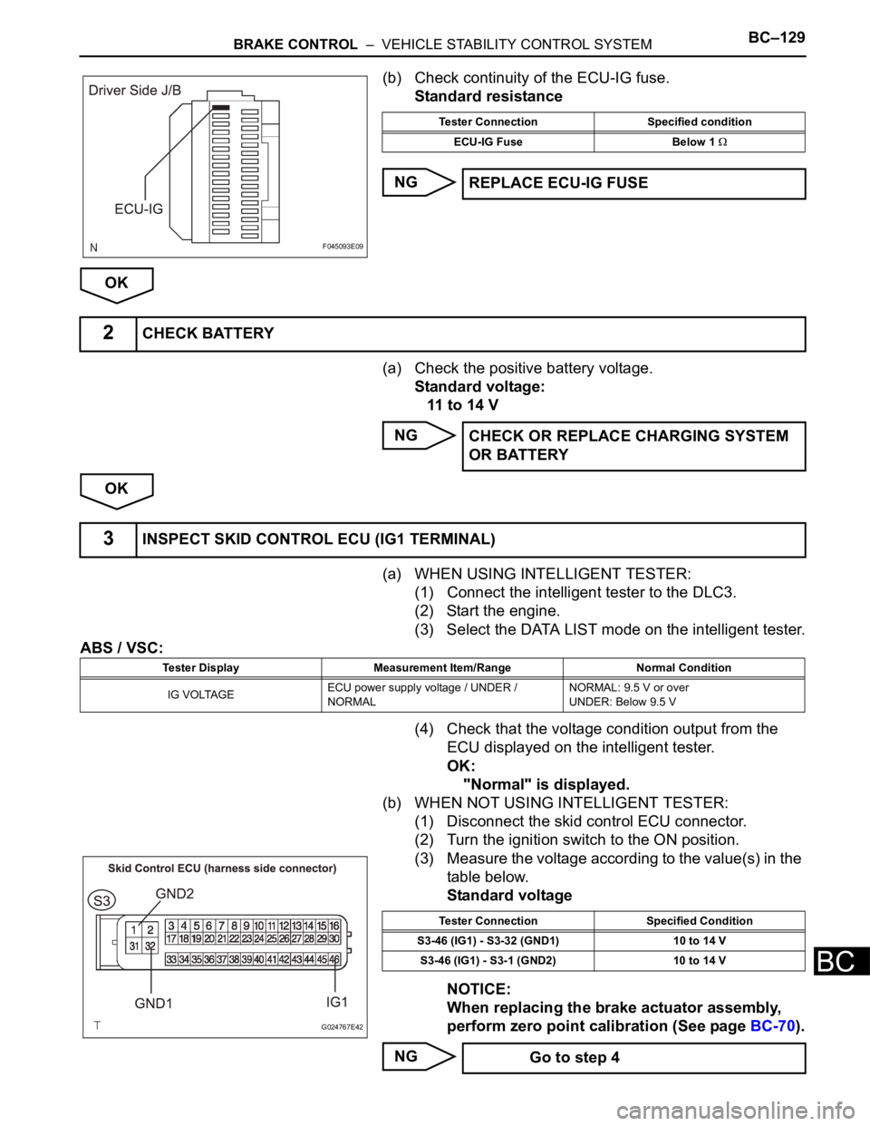
(a) WHEN USING INTELLIGENT TESTER:
(1) Connect the intelligent tester to the DLC3.
(2) Start the engine.
(3) Select the DATA LIST mode on the intelligent tester.
ABS / VSC:
(4) Check that the voltage condition output from the
ECU displayed on the intelligent tester.
OK:
"Normal" is displayed.
(b) WHEN NOT USING INTELLIGENT TESTER:
(1) Disconnect the skid control ECU connector.
(2) Turn the ignition switch to the ON position.
(3) Measure the voltage according to the value(s) in the
table below.
Standard voltage
NOTICE:
When replacing the brake actuator assembly,
perform zero point calibration (See page BC-70).
NG
F045093E09
Tester Connection Specified condition
ECU-IG Fuse Below 1
REPLACE ECU-IG FUSE
2CHECK BATTERY
CHECK OR REPLACE CHARGING SYSTEM
OR BATTERY
3INSPECT SKID CONTROL ECU (IG1 TERMINAL)
Tester Display Measurement Item/Range Normal Condition
IG VOLTAGEECU power supply voltage / UNDER /
NORMALNORMAL: 9.5 V or over
UNDER: Below 9.5 V
G024767E42
Tester Connection Specified Condition
S3-46 (IG1) - S3-32 (GND1) 10 to 14 V
S3-46 (IG1) - S3-1 (GND2) 10 to 14 V
Go to step 4
Page 2493 of 3000

BRAKE CONTROL – VEHICLE STABILITY CONTROL SYSTEMBC–131
BC
DESCRIPTION
Master cylinder pressure sensor is connected to the skid control ECU in the actuator.
INSPECTION PROCEDURE
(a) Connect the intelligent tester to the DLC3.
(b) Start the engine.
(c) Select the DATA LIST mode on the intelligent tester.
ABS / VSC:
(d) Check that the brake fluid pressure value of the master
cylinder pressure sensor indicated on the intelligent
tester, changes when the brake pedal is depressed.
OK:
Brake fluid pressure value should change.
NOTICE:
When replacing the brake actuator assembly,
perform zero point calibration (See page BC-70).
NG
OK
DTC C1246/46 Master Cylinder Pressure Sensor Malfunction
DTC Code DTC Detection Condition Trouble Area
C1246/46When any of the following is detected:
1. When the vehicle speed is 7 km/h (4 mph) or more
and PMC terminal voltage of skid control ECU
exceeds 0.86 V, the condition that the voltage does
not change by 0.005 V or more continues for 30
sec.
2. Noise in terminal PMC of skid control ECU occurs 7
times or more within 5 sec.
3. When the stop light switch is off, the condition that
PMC terminal voltage of skid control ECU is 0.86 V
or more, or less than 0.3 V continues for 5 sec. or
more.
4. When IG1 terminal voltage is between 9.5 and 17.2
V, the condition that the VCM terminal voltage of
skid control ECU is out of the range from 4.4 to 5.6
V continues for 1.2 sec. or more.
5. When VCM terminal voltage of skid control ECU is
between 4.4 and 5.6 V, the condition that the PMC
terminal voltage of skid control ECU is out of the
range from 0.14 to 4.85 V continues for 1.2 sec. or
more.• Master cylinder pressure sensor
• Master cylinder pressure sensor circuit
1READ VALUE ON INTELLIGENT TESTER (MASTER CYLINDER PRESSURE SENSOR)
Tester Display Measurement Item/Range Normal Condition
MAS CYL PRS 1Master cylinder pressure sensor 1 reading /
min.: 0 V, max.: 5 VWhen brake pedal is released : 0.3 to 0.9 V
Go to step 2
REPLACE BRAKE ACTUATOR ASSEMBLY
Page 2503 of 3000
BRAKE CONTROL – VEHICLE STABILITY CONTROL SYSTEMBC–141
BC
OK:
The centered position of the steering wheel is
correctly set.
NG
OK
(a) Turn the ignition switch off.
(b) Clear the DTC (See page BC-82).
(c) Start the engine.
(d) Drive the vehicle and turn the steering wheel to the right
and left at the speed of 35 km/h (22 mph) or more.
(e) Check if the same DTC is recorded (See page BC-82).
Result
B
AADJUST FRONT WHEEL ALIGNMENT OR
STEERING POSITION
3RECONFIRM DTC
Result Proceed to
DTC (C1290/66) is not outputA
DTC (C1290/66) is outputB
REPLACE BRAKE ACTUATOR ASSEMBLY
END