Page 2544 of 3000

BC–178BRAKE CONTROL – BRAKE ACTUATOR (w/ VSC)
BC
ON-VEHICLE INSPECTION
1. CONNECT INTELLIGENT TESTER
(a) Connect the intelligent tester to the DLC3.
(b) Start the engine and run at idle.
(c) Select the ACTIVE TEST mode on the intelligent
tester.
HINT:
Please refer to the intelligent tester operator's
manual for further details.
2. INSPECT ACTUATOR MOTOR OPERATION
(a) With the motor relay on, check the actuator motor
operation noise.
(b) Turn the motor relay off.
(c) Depress the brake pedal and hold it for
approximately 15 seconds. Check that the brake
pedal cannot be depressed.
(d) With the motor relay on, check that the pedal does
not pulsate.
NOTICE:
Do not keep the motor relay turned on for more
than 5 seconds continuously. When operating it
continuously, set an interval of more than 20
seconds.
(e) Turn the motor relay off and release the brake
pedal.
3. INSPECT RIGHT FRONT WHEEL OPERATION
NOTICE:
Never turn on the solenoids in a manner different to
those described below.
(a) With the brake pedal depressed, perform the
following operations.
(b) Turn the SFRH and SFRR solenoids on
simultaneously, and check that the pedal cannot be
depressed.
NOTICE:
Do not keep the solenoid turned on for more
than 10 seconds continuously. When operating
it continuously, set an interval of more than 20
seconds.
(c) Turn the SFRH and SFRR solenoids off
simultaneously, and check that the pedal can be
depressed.
(d) Turn the motor relay on, and check that the pedal
returns.
NOTICE:
Do not keep the motor relay turned on for more
than 5 seconds continuously. When operating it
continuously, set an interval of more than 20
seconds.
(e) Turn the motor relay off and release the brake
pedal.
A080036E03
Page 2555 of 3000

BRAKE CONTROL – BRAKE ACTUATOR (w/o VSC)BC–183
BC
ON-VEHICLE INSPECTION
1. CONNECT INTELLIGENT TESTER
(a) Connect the intelligent tester to the DLC3.
(b) Start the engine and run at idle.
(c) Select the ACTIVE TEST mode on the intelligent
tester.
HINT:
Please refer to the intelligent tester operator's
manual for further details.
2. INSPECT ACTUATOR MOTOR OPERATION
(a) With the motor relay on, check the actuator motor
operation noise.
(b) Turn the motor relay off.
(c) Depress the brake pedal and hold it for
approximately 15 seconds. Check that the brake
pedal cannot be depressed.
(d) With the motor relay on, check that the pedal does
not pulsate.
NOTICE:
Do not keep the motor relay turned on for more
than 5 seconds continuously. When operating it
continuously, set an interval of more than 20
seconds.
(e) Turn the motor relay off and release the brake
pedal.
3. INSPECT RIGHT FRONT WHEEL OPERATION
NOTICE:
Never turn on the solenoids in a manner different to
those described below.
(a) With the brake pedal depressed, perform the
following operations.
(b) Turn the SFRH and SFRR solenoids on
simultaneously, and check that the pedal cannot be
depressed.
NOTICE:
Do not keep the solenoid turned on for more
than 10 seconds continuously. When operating
it continuously, set an interval of more than 20
seconds.
(c) Turn the SFRH and SFRR solenoids off
simultaneously, and check that the pedal can be
depressed.
(d) Turn the motor relay on, and check that the pedal
returns.
NOTICE:
Do not keep the motor relay turned on for more
than 5 seconds continuously. When operating it
continuously, set an interval of more than 20
seconds.
(e) Turn the motor relay off and release the brake
pedal.
A080036E03
Page 2568 of 3000

BC–32BRAKE CONTROL – ANTI-LOCK BRAKE SYSTEM
BC
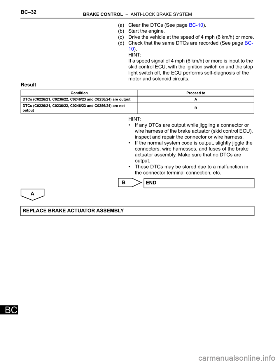
(a) Clear the DTCs (See page BC-10).
(b) Start the engine.
(c) Drive the vehicle at the speed of 4 mph (6 km/h) or more.
(d) Check that the same DTCs are recorded (See page BC-
10).
HINT:
If a speed signal of 4 mph (6 km/h) or more is input to the
skid control ECU, with the ignition switch on and the stop
light switch off, the ECU performs self-diagnosis of the
motor and solenoid circuits.
Result
HINT:
• If any DTCs are output while jiggling a connector or
wire harness of the brake actuator (skid control ECU),
inspect and repair the connector or wire harness.
• If the normal system code is output, slightly jiggle the
connectors, wire harnesses, and fuses of the brake
actuator assembly. Make sure that no DTCs are
output.
• These DTCs may be stored due to a malfunction in
the connector terminal connection, etc.
B
A
Condition Proceed to
DTCs (C0226/21, C0236/22, C0246/23 and C0256/24) are output A
DTCs (C0226/21, C0236/22, C0246/23 and C0256/24) are not
outputB
END
REPLACE BRAKE ACTUATOR ASSEMBLY
Page 2573 of 3000

BRAKE CONTROL – ANTI-LOCK BRAKE SYSTEMBC–35
BC
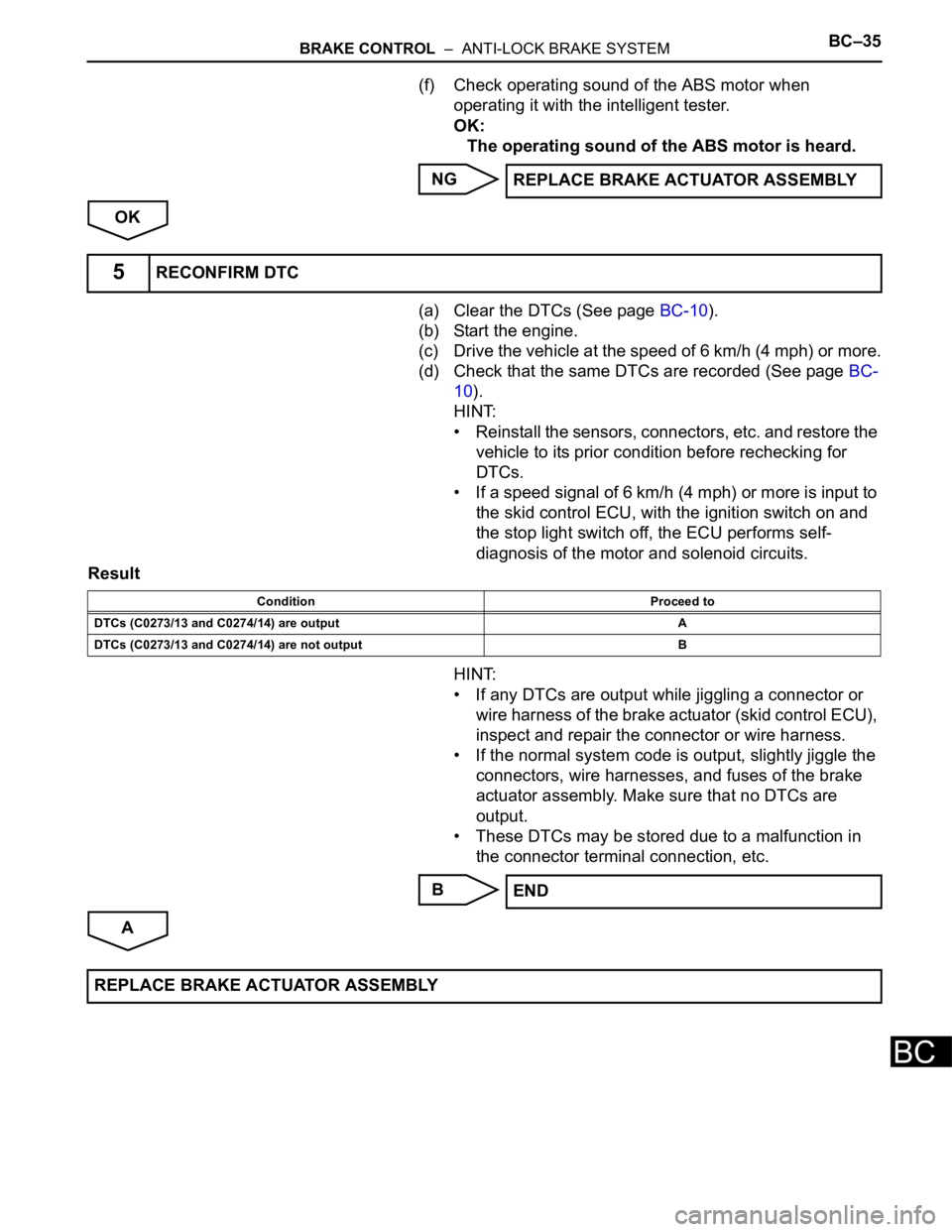
(f) Check operating sound of the ABS motor when
operating it with the intelligent tester.
OK:
The operating sound of the ABS motor is heard.
NG
OK
(a) Clear the DTCs (See page BC-10).
(b) Start the engine.
(c) Drive the vehicle at the speed of 6 km/h (4 mph) or more.
(d) Check that the same DTCs are recorded (See page BC-
10).
HINT:
• Reinstall the sensors, connectors, etc. and restore the
vehicle to its prior condition before rechecking for
DTCs.
• If a speed signal of 6 km/h (4 mph) or more is input to
the skid control ECU, with the ignition switch on and
the stop light switch off, the ECU performs self-
diagnosis of the motor and solenoid circuits.
Result
HINT:
• If any DTCs are output while jiggling a connector or
wire harness of the brake actuator (skid control ECU),
inspect and repair the connector or wire harness.
• If the normal system code is output, slightly jiggle the
connectors, wire harnesses, and fuses of the brake
actuator assembly. Make sure that no DTCs are
output.
• These DTCs may be stored due to a malfunction in
the connector terminal connection, etc.
B
AREPLACE BRAKE ACTUATOR ASSEMBLY
5RECONFIRM DTC
Condition Proceed to
DTCs (C0273/13 and C0274/14) are output A
DTCs (C0273/13 and C0274/14) are not output B
END
REPLACE BRAKE ACTUATOR ASSEMBLY
Page 2577 of 3000

BRAKE CONTROL – ANTI-LOCK BRAKE SYSTEMBC–37
BC
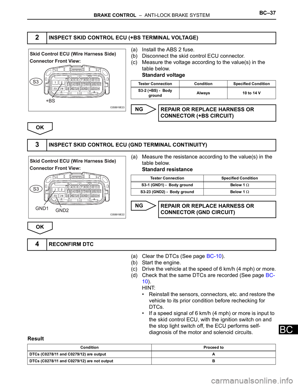
(a) Install the ABS 2 fuse.
(b) Disconnect the skid control ECU connector.
(c) Measure the voltage according to the value(s) in the
table below.
Standard voltage
NG
OK
(a) Measure the resistance according to the value(s) in the
table below.
Standard resistance
NG
OK
(a) Clear the DTCs (See page BC-10).
(b) Start the engine.
(c) Drive the vehicle at the speed of 6 km/h (4 mph) or more.
(d) Check that the same DTCs are recorded (See page BC-
10).
HINT:
• Reinstall the sensors, connectors, etc. and restore the
vehicle to its prior condition before rechecking for
DTCs.
• If a speed signal of 6 km/h (4 mph) or more is input to
the skid control ECU, with the ignition switch on and
the stop light switch off, the ECU performs self-
diagnosis of the motor and solenoid circuits.
Result
2INSPECT SKID CONTROL ECU (+BS TERMINAL VOLTAGE)
C058919E23
Tester Connection Condition Specified Condition
S3-2 (+BS) - Body
groundAlways 10 to 14 V
REPAIR OR REPLACE HARNESS OR
CONNECTOR (+BS CIRCUIT)
3INSPECT SKID CONTROL ECU (GND TERMINAL CONTINUITY)
C058919E22
Tester Connection Specified Condition
S3-1 (GND1) - Body ground Below 1
S3-23 (GND2) - Body ground Below 1
REPAIR OR REPLACE HARNESS OR
CONNECTOR (GND CIRCUIT)
4RECONFIRM DTC
Condition Proceed to
DTCs (C0278/11 and C0279/12) are output A
DTCs (C0278/11 and C0279/12) are not output B
Page 2583 of 3000

BC–40BRAKE CONTROL – ANTI-LOCK BRAKE SYSTEM
BC
(a) Check the battery voltage.
Standard voltage:
11 to 14 V
NG
OK
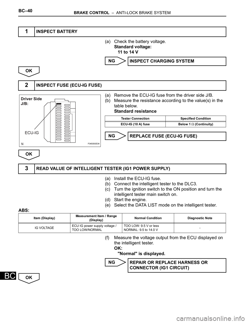
(a) Remove the ECU-IG fuse from the driver side J/B.
(b) Measure the resistance according to the value(s) in the
table below.
Standard resistance
NG
OK
(a) Install the ECU-IG fuse.
(b) Connect the intelligent tester to the DLC3.
(c) Turn the ignition switch to the ON position and turn the
intelligent tester main switch on.
(d) Start the engine.
(e) Select the DATA LIST mode on the intelligent tester.
ABS:
(f) Measure the voltage output from the ECU displayed on
the intelligent tester.
OK:
"Normal" is displayed.
NG
OK
1INSPECT BATTERY
INSPECT CHARGING SYSTEM
2INSPECT FUSE (ECU-IG FUSE)
F045093E04
Tester Connection Specified Condition
ECU-IG (10 A) fuse Below 1
(Continuity)
REPLACE FUSE (ECU-IG FUSE)
3READ VALUE OF INTELLIGENT TESTER (IG1 POWER SUPPLY)
Item (Display)Measurement Item / Range
(Display)Normal Condition Diagnostic Note
IG VOLTAGEECU IG power supply voltage /
TOO LOW/NORMALTOO LOW: 9.5 V or less
NORMAL: 9.5 to 14.0 V-
REPAIR OR REPLACE HARNESS OR
CONNECTOR (IG1 CIRCUIT)
Page 2600 of 3000
BR–22BRAKE – BRAKE BOOSTER
BR
INSPECTION
1. INSPECT BRAKE VACUUM CHECK VALVE
ASSEMBLY
(a) Check the vacuum check valve.
(1) Slide the clip and disconnect the vacuum hose.
(2) Remove the vacuum check valve.
(3) Check that there is ventilation from the booster
to the engine, and no ventilation from the
engine to the booster.
(4) If any fault is found, replace the vacuum check
valve.
F040007E06
Page 2605 of 3000
BR–10BRAKE – BRAKE PEDAL
BR
3. CHECK PEDAL FREE PLAY
(a) Stop the engine and depress the brake pedal
several times until there is no more vacuum left in
the booster.
(b) Push in the pedal until the beginning of the
resistance is felt. Measure the distance, as shown.
Pedal free play:
1 to 6 mm (0.04 to 0.24 in.)
4. CHECK PEDAL RESERVE DISTANCE
(a) Release the parking brake pedal.
With the engine running, depress the pedal and
measure the pedal reserve distance, as shown.
Pedal reserve distance from asphalt sheet at 490
N (50 kgf, 110 lbf):
More than 52 mm (2.0 in.)
HINT:
If the distance is out of the specification,
troubleshoot the brake system.
G024662E01
R000934E13