2007 TOYOTA SIENNA change time
[x] Cancel search: change timePage 2456 of 3000

BC–94BRAKE CONTROL – VEHICLE STABILITY CONTROL SYSTEM
BC
DESCRIPTION
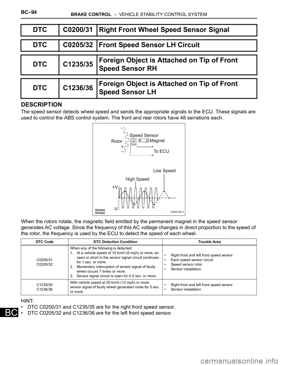
The speed sensor detects wheel speed and sends the appropriate signals to the ECU. These signals are
used to control the ABS control system. The front and rear rotors have 48 serrations each.
When the rotors rotate, the magnetic field emitted by the permanent magnet in the speed sensor
generates AC voltage. Since the frequency of this AC voltage changes in direct proportion to the speed of
the rotor, the frequency is used by the ECU to detect the speed of each wheel.
HINT:
• DTC C0200/31 and C1235/35 are for the right front speed sensor.
• DTC C0205/32 and C1236/36 are for the left front speed sensor.
DTC C0200/31 Right Front Wheel Speed Sensor Signal
DTC C0205/32 Front Speed Sensor LH Circuit
DTC C1235/35Foreign Object is Attached on Tip of Front
Speed Sensor RH
DTC C1236/36Foreign Object is Attached on Tip of Front
Speed Sensor LH
DTC Code DTC Detection Condition Trouble Area
C0200/31
C0205/32When any of the following is detected:
1. At a vehicle speed of 10 km/h (6 mph) or more, an
open or short in the sensor signal circuit continues
for 1 sec. or more.
2. Momentary interruption of sensor signal of faulty
wheel occurs 7 times or more.
3. Sensor signal circuit is open for 0.5 sec. or more.• Right front and left front speed sensor
• Each speed sensor circuit
• Speed sensor rotor
• Sensor installation
C1235/35
C1236/36With vehicle speed at 20 km/h (12 mph) or more,
sensor signal of faulty wheel generated noise for 5 sec.
or more.• Right front and left front speed sensor
• Sensor installation
F000010E12
Page 2487 of 3000

BRAKE CONTROL – VEHICLE STABILITY CONTROL SYSTEMBC–125
BC
DESCRIPTION
The yaw rate sensor and deceleration sensor signal is sent to the skid control ECU through the CAN
communication system. When there is a malfunction in the communication, it will be detected by the
diagnosis function.
DTC C1232/32 Stuck in Deceleration Sensor
DTC C1234/34 Yaw Rate Sensor Malfunction
DTC C1243/43 Acceleration Sensor Stuck Malfunction
DTC C1244/44 Open or Short in Deceleration Sensor Circuit
DTC C1245/45 Acceleration Sensor Output Malfunction
DTC C1381/97Yaw Rate and / or Acceleration Sensor Power
Supply Voltage Malfunction
DTC Code DTC Detection Condition Trouble Area
C1232/32At a vehicle speed of 10 km/h (6 mph) or more, either
GL1 or GL2 (input signal) does not change for 30 sec.
or more.Yaw rate and deceleration sensor
C1234/34 The yaw rate sensor malfunction signal is received Yaw rate and deceleration sensor
C1243/43While vehicle speed becomes 0 km/h (0 mph) from 30
km/h (18 mph) or more, the condition that both GL1 and
GL2 signals of ECU terminals do not change 2 LSB or
more continued in a sequence 16 times.• Yaw rate and deceleration sensor
• Yaw rate and deceleration sensor circuit
C1244/44When either of the following is detected:
1. With vehicle speed at 0 km/h, after the difference of
output absolute value of G conversion value
between deceleration sensor terminals GL1 and
GL2 becomes 0.6 G or more, and the condition that
does not become 0.4 G continues for 60 sec. or
more.
2. Deceleration sensor malfunction signal is received.• Yaw rate and deceleration sensor
• Yaw rate and deceleration sensor circuit
C1245/45At the vehicle speed of 30 km/h (18 mph) or more, the
acceleration and deceleration values calculated from
the deceleration sensor values and from vehicle speed
are different, and the condition that the difference
exceeds 0.35 G continues for 60 sec. or more.• Yaw rate and deceleration sensor
• Yaw rate and deceleration sensor circuit
C1381/97With vehicle speed at 3 km/h or more, malfunction
signal of deceleration sensor terminal IG1 is received
for 10 sec. or more.• Yaw rate and deceleration sensor
• Yaw rate and deceleration sensor power source
circuit
Page 2493 of 3000

BRAKE CONTROL – VEHICLE STABILITY CONTROL SYSTEMBC–131
BC
DESCRIPTION
Master cylinder pressure sensor is connected to the skid control ECU in the actuator.
INSPECTION PROCEDURE
(a) Connect the intelligent tester to the DLC3.
(b) Start the engine.
(c) Select the DATA LIST mode on the intelligent tester.
ABS / VSC:
(d) Check that the brake fluid pressure value of the master
cylinder pressure sensor indicated on the intelligent
tester, changes when the brake pedal is depressed.
OK:
Brake fluid pressure value should change.
NOTICE:
When replacing the brake actuator assembly,
perform zero point calibration (See page BC-70).
NG
OK
DTC C1246/46 Master Cylinder Pressure Sensor Malfunction
DTC Code DTC Detection Condition Trouble Area
C1246/46When any of the following is detected:
1. When the vehicle speed is 7 km/h (4 mph) or more
and PMC terminal voltage of skid control ECU
exceeds 0.86 V, the condition that the voltage does
not change by 0.005 V or more continues for 30
sec.
2. Noise in terminal PMC of skid control ECU occurs 7
times or more within 5 sec.
3. When the stop light switch is off, the condition that
PMC terminal voltage of skid control ECU is 0.86 V
or more, or less than 0.3 V continues for 5 sec. or
more.
4. When IG1 terminal voltage is between 9.5 and 17.2
V, the condition that the VCM terminal voltage of
skid control ECU is out of the range from 4.4 to 5.6
V continues for 1.2 sec. or more.
5. When VCM terminal voltage of skid control ECU is
between 4.4 and 5.6 V, the condition that the PMC
terminal voltage of skid control ECU is out of the
range from 0.14 to 4.85 V continues for 1.2 sec. or
more.• Master cylinder pressure sensor
• Master cylinder pressure sensor circuit
1READ VALUE ON INTELLIGENT TESTER (MASTER CYLINDER PRESSURE SENSOR)
Tester Display Measurement Item/Range Normal Condition
MAS CYL PRS 1Master cylinder pressure sensor 1 reading /
min.: 0 V, max.: 5 VWhen brake pedal is released : 0.3 to 0.9 V
Go to step 2
REPLACE BRAKE ACTUATOR ASSEMBLY
Page 2559 of 3000

BRAKE CONTROL – ANTI-LOCK BRAKE SYSTEMBC–25
BC
DESCRIPTION
Refer to DTCs C0200/31, C0205/32, C1235/35, and C1236/36 (See page BC-17).
DTCs C1273/73 to C1278/78 can be deleted when the speed sensor sends a vehicle speed signal or the
Test Mode ends. DTCs C1273/73 to C1278/78 are output only in the Test Mode.
HINT:
• DTC C0210/33 and C1238/38 are for the rear speed sensor RH.
• DTC C0215/34 and C1239/39 are for the rear speed sensor LH.
DTC C0210/33 Rear Speed Sensor RH Circuit
DTC C0215/34 Rear Speed Sensor LH Circuit
DTC C1238/38Foreign Object is Attached on Tip of Rear
Speed Sensor RH
DTC C1239/39Foreign Object is Attached on Tip of Rear
Speed Sensor LH
DTC C1273/73Low Output Signal of Rear Speed Sensor RH
(Test Mode DTC)
DTC C1274/74Low Output Signal of Rear Speed Sensor LH
(Test Mode DTC)
DTC C1277/77Abnormal Change in Output Signal of Rear
Speed Sensor RH (Test Mode DTC)
DTC C1278/78Abnormal Change in Output Signal of Rear
Speed Sensor LH (Test Mode DTC)
DTC No. DTC Detection Condition Trouble Area
C0210/33
C0215/34With vehicle speed at 10 km/h (6 mph) or more, sensor
signal circuit of faulty wheel is open or short for 1
second or more.
• Momentary interruption of sensor signal of faulty
wheel has occurred 7 times or more.
• Sensor signal circuit is open for 0.5 seconds or
more.• Rear speed sensor RH/LH
• Rear speed sensor RH/LH circuit
• Speed sensor rotor
• Sensor installation
• Brake actuator assembly
C1238/38
C1239/39At vehicle speed of 20 km/h (12 mph) or more, condition
that noise is included in speed sensor signal continues
for 5 seconds or more.• Rear speed sensor RH/LH
• Speed sensor rotor
• Sensor installation
• Brake actuator assembly
Page 2615 of 3000

BRAKE – BRAKE BOOSTERBR–19
BR
ON-VEHICLE INSPECTION
1. INSPECT BRAKE BOOSTER
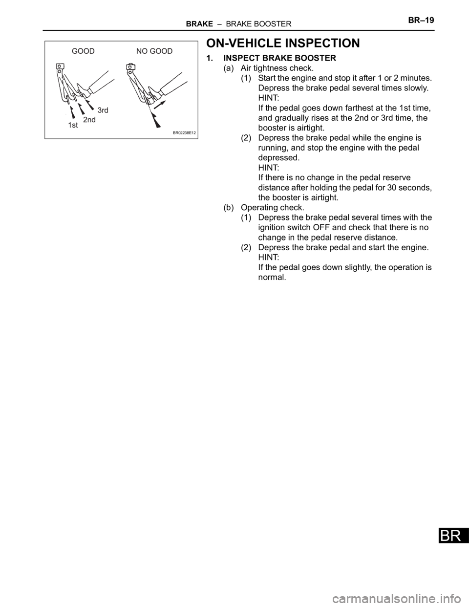
(a) Air tightness check.
(1) Start the engine and stop it after 1 or 2 minutes.
Depress the brake pedal several times slowly.
HINT:
If the pedal goes down farthest at the 1st time,
and gradually rises at the 2nd or 3rd time, the
booster is airtight.
(2) Depress the brake pedal while the engine is
running, and stop the engine with the pedal
depressed.
HINT:
If there is no change in the pedal reserve
distance after holding the pedal for 30 seconds,
the booster is airtight.
(b) Operating check.
(1) Depress the brake pedal several times with the
ignition switch OFF and check that there is no
change in the pedal reserve distance.
(2) Depress the brake pedal and start the engine.
HINT:
If the pedal goes down slightly, the operation is
normal.
BR02238E12
Page 2771 of 3000

AIR CONDITIONING – AIR CONDITIONING SYSTEM (for Automatic Air Conditioning Sys-
tem)AC–25
AC
(b) As each damper, motor and relay automatically
operate actuator check at 1-second intervals from
step No. 1 to No. 10 continuously, check the
temperature and air flow visually and by hand.
If the slower display is desired, press the DEF
switch and change it to step operation. Each time
the DEF switch is pressed, the display changes by 1
step.
HINT:
• Codes are displayed from smaller to larger
numbers in order.
• To cancel the check mode, press the OFF switch.
Step No.Display
codeConditions
Fr. Blower
levelFr. Air flow
ventAir inlet
damperMagnetic
clutchFr. Driver,
passenger
side air
mix
damperRr. Blower
levelRr. Air flow
ventRr. Air mix
damper
1 0 0 FACE FRESH OFF"COOL"
side
(Full
closed)0 FACE1"COOL"
side
(Full
closed)
2 1 1 FACE FRESH OFF"COOL"
side
(Full
closed)1 FACE1"COOL"
side
(Full
closed)
3 2 16 FACE FRESH ON"COOL"
side
(Full
closed)10 FACE1"COOL" /
"HOT"
(40% open)
4316FACEFRESH /
RECIRCUL
AT I O NON"COOL"
side
(Full
closed)10 FACE2"COOL" /
"HOT"
(40% open)
5416FACERECIRCUL
AT I O NON"COOL" /
"HOT"
(50% open)10 B/L"COOL" /
"HOT"
(40% open)
6516B/LRECIRCUL
AT I O NON"COOL" /
"HOT"
(50% open)10 B/L"COOL" /
"HOT"
(60% open)
7616FOOTRECIRCUL
AT I O NON"HOT" side
(Full open)10 B/L"COOL" /
"HOT"
(60% open)
8716FOOTRECIRCUL
AT I O NON
"HOT" side
(Full open)10 FOOT"COOL" /
"HOT"
(60% open)
9816FOOT /
DEF.RECIRCUL
AT I O NON"HOT" side
(Full open)10 FOOT"COOL" /
"HOT"
(86.5%
open)
10931DEF.RECIRCUL
AT I O NON"HOT" side
(Full open)31 FOOT"COOL" /
"HOT"
(86.5%
open)
Page 2904 of 3000

AIR CONDITIONING – AIR CONDITIONING SYSTEM (for Automatic Air Conditioning Sys-
tem)AC–15
AC
NOTICE:
*: Before measuring the resistance, leave the
vehicle as is for at least 1 minute and do not
operate the ignition switch, any other switches
or the doors.
DTC CHECK / CLEAR
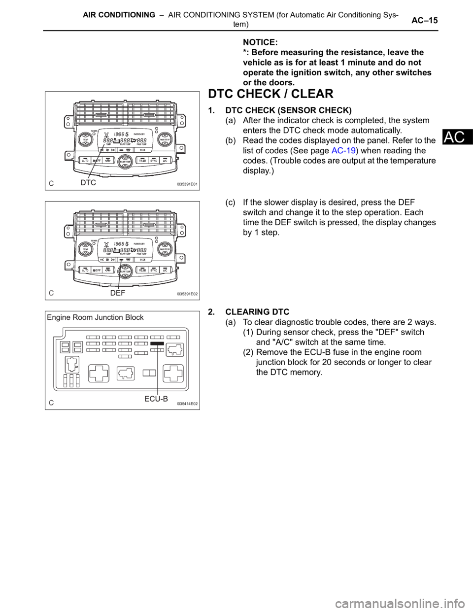
1. DTC CHECK (SENSOR CHECK)
(a) After the indicator check is completed, the system
enters the DTC check mode automatically.
(b) Read the codes displayed on the panel. Refer to the
list of codes (See page AC-19) when reading the
codes. (Trouble codes are output at the temperature
display.)
(c) If the slower display is desired, press the DEF
switch and change it to the step operation. Each
time the DEF switch is pressed, the display changes
by 1 step.
2. CLEARING DTC
(a) To clear diagnostic trouble codes, there are 2 ways.
(1) During sensor check, press the "DEF" switch
and "A/C" switch at the same time.
(2) Remove the ECU-B fuse in the engine room
junction block for 20 seconds or longer to clear
the DTC memory.
I035391E01
I035391E02
I035414E02
Page 2918 of 3000

AC–18AIR CONDITIONING – AIR CONDITIONING SYSTEM (for Automatic Air Conditioning Sys-
tem)
AC
DATA LIST / ACTIVE TEST
1. DATA LIST
HINT:
Using the intelligent tester to read the Data List allows
the values or states of switches, sensors, actuators and
other items to be read without removing any parts. This
non-intrusive inspection can be very useful because
intermittent conditions or signals may be discovered
before parts or wiring is disturbed. Reading the Data List
information early in troubleshooting is one way to save
diagnostic time.
(a) Connect the intelligent tester to the DLC3.
(b) Turn the ignition switch to the ON position.
(c) From the display on the tester, read the "DATA
LIST".
AIR CONDITIONER / DATA LIST
Tester Display Measurement Item/Range Normal Condition Diagnostic Note
ROOM TEMPRoom temperature sensor / min.:
-6.5
C (20.3F), max.: 57.25C
(135.05
F)Actual cabin temperature -
AMBI TEMP SENSAmbient temperature sensor /
min.: -23.3
C (-9.94F), max.:
65..95C (150.71F)Actual ambient temperature -
AMBI TEMPAdjusted ambient temperature /
min.: -30.8
C (-23.44F), max.:
50.8
C (123.44F)--
EVAP TEMPEvaporator temperature sensor /
min.: -29.7
C (-21.46F), max.:
59.55
C (139.19F)Actual evaporator temperature -
SOLAR SENS-DSolar sensor (D side) / min.: 0,
max.: 255Changes depending on
brightness (D side)-
SOLAR SENS-PSolar sensor (P side) / min.: 0,
max.: 255Changes depending on
brightness (P side)-
COOLANT TEMPEngine coolant temperature /
min.: 1.3
C (34.34F), max.:
90.55C (194.99F)Actual engine coolant
temperature-
SET TEMP-DSet temperature (D side) / min.: 0,
max. 255Actual set temperature (D side) -
SET TEMP-PSet temperature (P side) / min.: 0,
max. 255Actual set temperature (P side) -
ESTIMATE TEMP-DEstimated temperature (D side) /
min.: -358.4
C (-613.12F), max.:
358.4
C (677.12F)--
ESTIMATE TEMP-PEstimated temperature (P side) /
min.: -358.4
C (-613.12F), max.:
358.4
C (677.12F)--
A/M DAMP POS-DAir mix damper position (D side) /
min.: -14%, max.: 113.5%Changes depending on the set
temperature (D side)-
A/M DAMP POS-PAir mix damper position (P side) /
min.: -14%, max.: 113.5%Changes depending on the set
temperature (P side)-
A/I DAMP POSAir inlet damper position / min.: -
14%, max.: 113.5%Changes depending on air inlet
damper position-
A/O DAMP POSAir outlet damper position / min.: -
14%, max.: 113.5%Changes depending on air outlet
damper position-
A/M DAMP TARG-DAir mix damper target position (D
side) / min.: -14%, max.: 113.5%Changes depending on the set
temperature (D side)-
A/M DAMP TARG-PAir mix damper target position (P
side) / min.: -14%, max.: 113.5%Changes depending on the set
temperature (P side)-