2007 TOYOTA SIENNA change time
[x] Cancel search: change timePage 1192 of 3000

EC–182GR-FE EMISSION CONTROL – AIR FUEL RATIO SENSOR (for 2WD)
EC
ON-VEHICLE INSPECTION
HINT:
The type of ignition switch on this model differs according to
the specifications of the vehicle. For the expressions used in
this section, refer to the "EXPRESSIONS OF IGNITION
SWITCH" precaution (See page ES-1).
1. CHECK AIR FUEL RATIO COMPENSATION SYSTEM
(a) Connect the intelligent tester to the DLC3.
(b) Turn the ignition switch to the ON position.
(c) Select the following menu items: Data List / A/FS B1
S1 and O2S B1 S2.
(d) Warm up the A/F sensor with the engine speed at
2500 rpm for approximately 2 minutes.
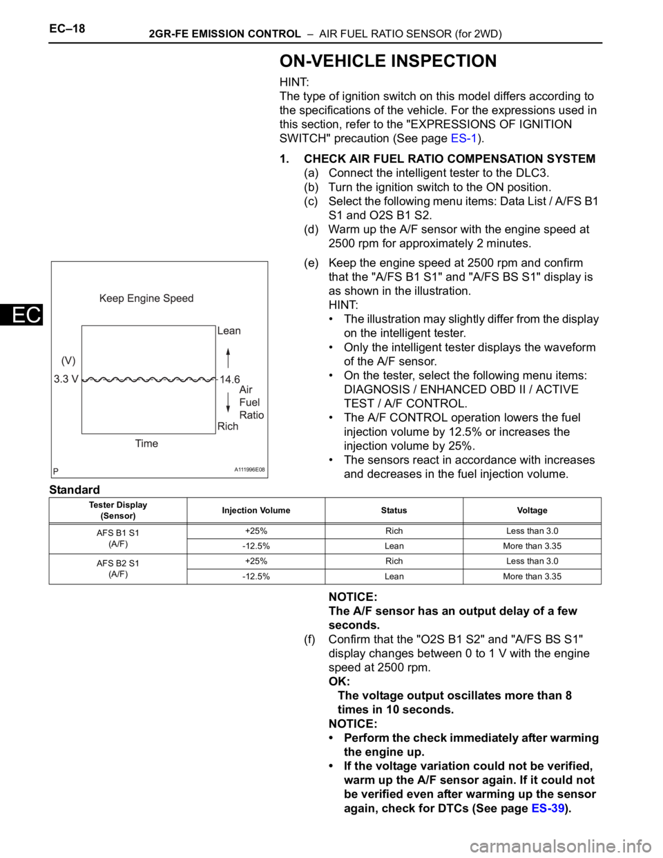
(e) Keep the engine speed at 2500 rpm and confirm
that the "A/FS B1 S1" and "A/FS BS S1" display is
as shown in the illustration.
HINT:
• The illustration may slightly differ from the display
on the intelligent tester.
• Only the intelligent tester displays the waveform
of the A/F sensor.
• On the tester, select the following menu items:
DIAGNOSIS / ENHANCED OBD II / ACTIVE
TEST / A/F CONTROL.
• The A/F CONTROL operation lowers the fuel
injection volume by 12.5% or increases the
injection volume by 25%.
• The sensors react in accordance with increases
and decreases in the fuel injection volume.
Standard
NOTICE:
The A/F sensor has an output delay of a few
seconds.
(f) Confirm that the "O2S B1 S2" and "A/FS BS S1"
display changes between 0 to 1 V with the engine
speed at 2500 rpm.
OK:
The voltage output oscillates more than 8
times in 10 seconds.
NOTICE:
• Perform the check immediately after warming
the engine up.
• If the voltage variation could not be verified,
warm up the A/F sensor again. If it could not
be verified even after warming up the sensor
again, check for DTCs (See page ES-39).
A111996E08
Tester Display
(Sensor)Injection Volume Status Voltage
AFS B1 S1
(A/F)+25% Rich Less than 3.0
-12.5% Lean More than 3.35
AFS B2 S1
(A/F)+25% Rich Less than 3.0
-12.5% Lean More than 3.35
Page 1196 of 3000

2GR-FE EMISSION CONTROL – AIR FUEL RATIO SENSOR (for 4WD)EC–25
EC
ON-VEHICLE INSPECTION
HINT:
The type of ignition switch on this model differs according to
the specifications of the vehicle. For the expressions used in
this section, refer to the "EXPRESSIONS OF IGNITION
SWITCH" precaution (See page ES-1).
1. CHECK AIR FUEL RATIO COMPENSATION SYSTEM
(a) Connect the intelligent tester to the DLC3.
(b) Turn the ignition switch to the ON position.
(c) Select the following menu items: Data List / A/FS B1
S1 and O2S B1 S2.
(d) Warm up the A/F sensor with the engine speed at
2500 rpm for approximately 2 minutes.
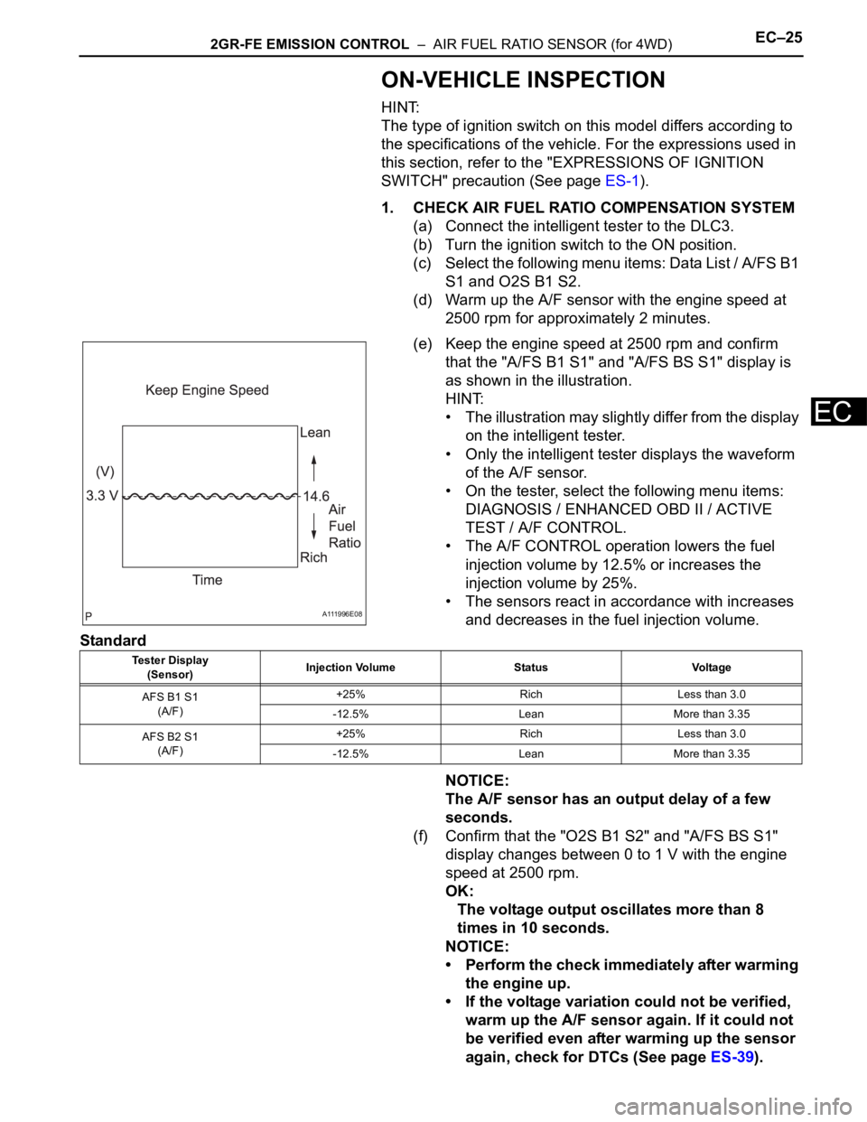
(e) Keep the engine speed at 2500 rpm and confirm
that the "A/FS B1 S1" and "A/FS BS S1" display is
as shown in the illustration.
HINT:
• The illustration may slightly differ from the display
on the intelligent tester.
• Only the intelligent tester displays the waveform
of the A/F sensor.
• On the tester, select the following menu items:
DIAGNOSIS / ENHANCED OBD II / ACTIVE
TEST / A/F CONTROL.
• The A/F CONTROL operation lowers the fuel
injection volume by 12.5% or increases the
injection volume by 25%.
• The sensors react in accordance with increases
and decreases in the fuel injection volume.
Standard
NOTICE:
The A/F sensor has an output delay of a few
seconds.
(f) Confirm that the "O2S B1 S2" and "A/FS BS S1"
display changes between 0 to 1 V with the engine
speed at 2500 rpm.
OK:
The voltage output oscillates more than 8
times in 10 seconds.
NOTICE:
• Perform the check immediately after warming
the engine up.
• If the voltage variation could not be verified,
warm up the A/F sensor again. If it could not
be verified even after warming up the sensor
again, check for DTCs (See page ES-39).
A111996E08
Tester Display
(Sensor)Injection Volume Status Voltage
AFS B1 S1
(A/F)+25% Rich Less than 3.0
-12.5% Lean More than 3.35
AFS B2 S1
(A/F)+25% Rich Less than 3.0
-12.5% Lean More than 3.35
Page 1435 of 3000

U151E AUTOMATIC TRANSAXLE – AUTOMATIC TRANSAXLE SYSTEMAX–69
AX
INSPECTION PROCEDURE
HINT:
Using the intelligent tester to perform ACTIVE TEST allows relays, VSVs, actuators and other items to be
operated without removing any parts. This non-intrusive functional inspection can be very useful because
intermittent operation may be discovered before parts or wiring is disturbed. Performing ACTIVE TEST
early in troubleshooting is one way to save diagnostic time. DATA LIST information can be displayed while
performing ACTIVE TEST.
1. PERFORM ACTIVE TEST
(a) Warm up the engine.
(b) Turn the ignition switch off.
(c) Connect the intelligent tester together with the CAN VIM (controller area network vehicle
interface module) to the DLC3.
(d) Turn the ignition switch to the ON position.
(e) Turn on the tester.
(f) Select the item "DIAGNOSIS / ENHANCED OBD II / ACTIVE TEST".
(g) According to the display on the tester, perform the "ACTIVE TEST".
HINT:
• This test can be conducted when the vehicle speed is 60 km/h (37 mph) or more.
• This test can be conducted in the 5th gear.
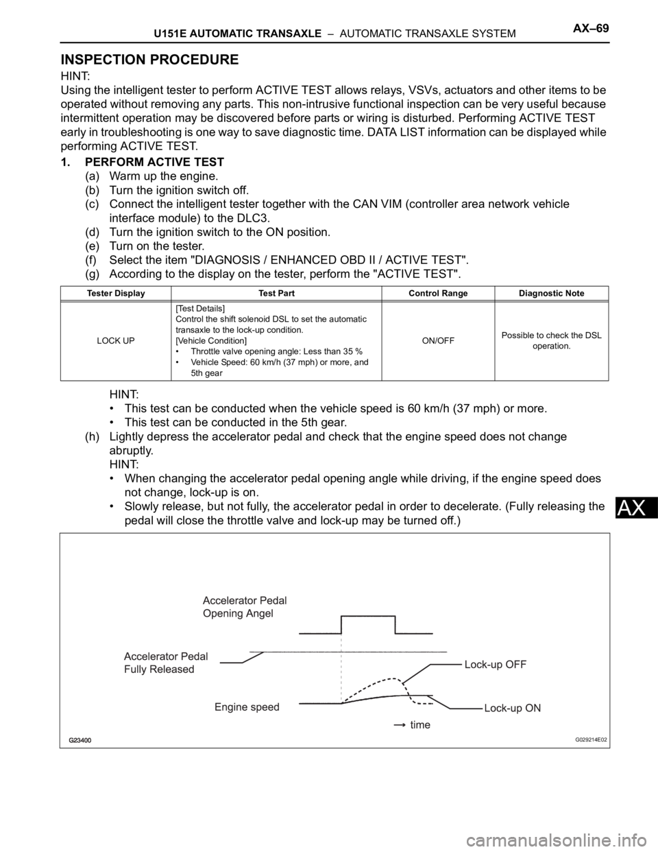
(h) Lightly depress the accelerator pedal and check that the engine speed does not change
abruptly.
HINT:
• When changing the accelerator pedal opening angle while driving, if the engine speed does
not change, lock-up is on.
• Slowly release, but not fully, the accelerator pedal in order to decelerate. (Fully releasing the
pedal will close the throttle valve and lock-up may be turned off.)
Tester Display Test Part Control Range Diagnostic Note
LOCK UP[Test Details]
Control the shift solenoid DSL to set the automatic
transaxle to the lock-up condition.
[Vehicle Condition]
• Throttle valve opening angle: Less than 35 %
• Vehicle Speed: 60 km/h (37 mph) or more, and
5th gearON/OFFPossible to check the DSL
operation.
G029214E02
Page 1440 of 3000

AX–74U151E AUTOMATIC TRANSAXLE – AUTOMATIC TRANSAXLE SYSTEM
AX
OFF malfunction:
ON malfunction:
TYPICAL MALFUNCTION THRESHOLDS
Either of the following conditions is met: OFF malfunction or ON malfunction
OFF malfunction:
2 detections are necessary per driving cycle:
1st detection; temporary flag ON
2nd detection; pending fault code ON
ON malfunction:
INSPECTION PROCEDURE
HINT:
Using the intelligent tester to perform ACTIVE TEST allows relays, VSVs, actuators and other items to be
operated without removing any parts. This non-intrusive functional inspection can be very useful because
intermittent operation may be discovered before parts or wiring is disturbed. Performing ACTIVE TEST
early in troubleshooting is one way to save diagnostic time. DATA LIST information can be displayed while
performing ACTIVE TEST.
1. PERFORM ACTIVE TEST
(a) Warm up the engine.
(b) Turn the ignition switch off.
(c) Connect the intelligent tester together with the CAN VIM (controller area network vehicle
interface module) to the DLC3.
(d) Turn the ignition switch to the ON position.
(e) Turn on the tester.
(f) Select the item "DIAGNOSIS / ENHANCED OBD II / ACTIVE TEST / SHIFT".
(g) According to the display on the tester, perform the "ACTIVE TEST".
HINT:
While driving, the shift position can be forcibly changed with the intelligent tester.
Shift solenoid valve SL3 circuit Not circuit malfunction
Shift solenoid valve S4 circuit Not circuit malfunction
Shift solenoid valve SR circuit Not circuit malfunction
Shift solenoid valve DSL circuit Not circuit malfunction
Electronic throttle systemNot circuit malfunction
ECM selected gear1st
Vehicle speedLess than 40 km/h (24.9 mph)
Throttle valve opening angle4.5% or more at engine speed 1,900 rpm
(Varies with engine speed)
ECM selected gear2nd
Throttle valve opening angle4.5% or more at engine speed 1,900 rpm
(Varies with engine speed)
Input (turbine) speed/Intermediate shaft speed 1.49 to 1.63
Input (turbine) speed/Intermediate shaft speed 2.72 to 2.86
Page 1453 of 3000

U151E AUTOMATIC TRANSAXLE – AUTOMATIC TRANSAXLE SYSTEMAX–87
AX
INSPECTION PROCEDURE
HINT:
Using the intelligent tester to perform ACTIVE TEST allows relays, VSVs, actuators and other items to be
operated without removing any parts. This non-intrusive functional inspection can be very useful because
intermittent operation may be discovered before parts or wiring is disturbed. Performing ACTIVE TEST
early in troubleshooting is one way to save diagnostic time. DATA LIST information can be displayed while
performing ACTIVE TEST.
1. PERFORM ACTIVE TEST
(a) Warm up the engine.
(b) Turn the ignition switch off.
(c) Connect the intelligent tester together with the CAN VIM (controller area network vehicle
interface module) to the DLC3.
(d) Turn the ignition switch to the ON position.
(e) Turn on the tester.
(f) Select the item "DIAGNOSIS / ENHANCED OBD II / ACTIVE TEST / SHIFT".
(g) According to the display on the tester, perform the "ACTIVE TEST".
HINT:
While driving, the shift position can be forcibly changed with the intelligent tester.
Comparing the shift position commanded by the ACTIVE TEST with the actual shift position enables you
to confirm the problem (See page AX-30).
HINT:
• This test can be conducted when the vehicle speed is 50 km/h (31 mph) or less.
• The shift position commanded by the ECM is shown in the DATA LIST/SHIFT display on the intelligent
tester.
(a) Connect the intelligent tester together with the CAN VIM
(controller area network vehicle interface module) to the
DLC3.
(b) Turn the ignition switch to the ON position and turn the
OBD II scan tool or the intelligent tester main switch ON.
(c) When you use intelligent tester:
Select the item "DIAGNOSIS / ENHANCED OBD II /
DTC INFO / CURRENT CODES".
(d) Read the DTCs using the OBD II scan tool or the
intelligent tester.
Result
Tester Display Test Part Control Range Diagnostic Note
SHIFT[Test Details]
Operate the shift solenoid valve and set the each
shift position by yourself.
[Vehicle Condition]
• IDL: ON
• Less than 50 km/h (31 mph)
[Others]
• Press "
" button: Shift up
• Press "
" button: Shift down1st/2nd/3rd/4th/5thPossible to check the
operation of the shift
solenoid valves.
1CHECK OTHER DTCS OUTPUT (IN ADDITION TO DTC P0771)
Result Proceed to
P0771 A
P0771 and other DTCs B
Page 1457 of 3000

U151E AUTOMATIC TRANSAXLE – AUTOMATIC TRANSAXLE SYSTEMAX–91
AX
ON malfunction (A):
ON malfunction (B):
ON malfunction (C):
INSPECTION PROCEDURE
HINT:
Using the intelligent tester to perform ACTIVE TEST allows relays, VSVs, actuators and other items to be
operated without removing any parts. This non-intrusive functional inspection can be very useful because
intermittent operation may be discovered before parts or wiring is disturbed. Performing ACTIVE TEST
early in troubleshooting is one way to save diagnostic time. DATA LIST information can be displayed while
performing ACTIVE TEST.
1. PERFORM ACTIVE TEST
(a) Warm up the engine.
(b) Turn the ignition switch off.
(c) Connect the intelligent tester together with the CAN VIM (controller area network vehicle
interface module) to the DLC3.
(d) Turn the ignition switch to the ON position.
(e) Turn on the tester.
(f) Select the item "DIAGNOSIS / ENHANCED OBD II / ACTIVE TEST / SHIFT".
(g) According to the display on the tester, perform the "ACTIVE TEST".
HINT:
While driving, the shift position can be forcibly changed with the intelligent tester.
Comparing the shift position commanded by the ACTIVE TEST with the actual shift position enables you
to confirm the problem (See page AX-30).
HINT:
• This test can be conducted when the vehicle speed is 50 km/h (31 mph) or less.
• The shift position commanded by the ECM is shown in the DATA LIST/SHIFT display on the intelligent
tester.
(a) Connect the intelligent tester together with the CAN VIM
(controller area network vehicle interface module) to the
DLC3.
(b) Turn the ignition switch to the ON position and turn the
OBD II scan tool or the intelligent tester main switch ON.
(c) When you use intelligent tester:
Input (turbine) speed/Intermediate shaft speed 2.72 to 2.86
Input (turbine) speed - Intermediate shaft speed 700 rpm or more
Input (turbine) speed - Intermediate shaft speedLess than -500 rpm
or
700 rpm or more
Tester Display Test Part Control Range Diagnostic Note
SHIFT[Test Details]
Operate the shift solenoid valve and set the each
shift position by yourself.
[Vehicle Condition]
• IDL: ON
• Less than 50 km/h (31 mph)
[Others]
• Press "
" button: Shift up
• Press "
" button: Shift down1st/2nd/3rd/4th/5thPossible to check the
operation of the shift
solenoid valves.
1CHECK OTHER DTCS OUTPUT (IN ADDITION TO DTC P0776)
Page 1470 of 3000

AX–104U151E AUTOMATIC TRANSAXLE – AUTOMATIC TRANSAXLE SYSTEM
AX
INSPECTION PROCEDURE
HINT:
Using the intelligent tester to perform ACTIVE TEST allows relays, VSVs, actuators and other items to be
operated without removing any parts. This non-intrusive functional inspection can be very useful because
intermittent operation may be discovered before parts or wiring is disturbed. Performing ACTIVE TEST
early in troubleshooting is one way to save diagnostic time. DATA LIST information can be displayed while
performing ACTIVE TEST.
1. PERFORM ACTIVE TEST
(a) Warm up the engine.
(b) Turn the ignition switch off.
(c) Connect the intelligent tester together with the CAN VIM (controller area network vehicle
interface module) to the DLC3.
(d) Turn the ignition switch to the ON position.
(e) Turn on the tester.
(f) Select the item "DIAGNOSIS / ENHANCED OBD II / ACTIVE TEST / SHIFT".
(g) According to the display on the tester, perform the "ACTIVE TEST".
HINT:
While driving, the shift position can be forcibly changed with the intelligent tester.
Comparing the shift position commanded by the ACTIVE TEST with the actual shift position enables you
to confirm the problem (See page AX-30).
HINT:
• This test can be conducted when the vehicle speed is 50 km/h (31 mph) or less.
• The shift position commanded by the ECM is shown in the DATA LIST/SHIFT display on the intelligent
tester.
(a) Connect the intelligent tester together with the CAN VIM
(controller area network vehicle interface module) to the
DLC3.
(b) Turn the ignition switch to the ON position and turn the
OBD II scan tool or the intelligent tester main switch ON.
(c) When you use intelligent tester:
Select the item "DIAGNOSIS / ENHANCED OBD II /
DTC INFO / CURRENT CODES".
(d) Read the DTCs using the OBD II scan tool or the
intelligent tester.
Result
Tester Display Test Part Control Range Diagnostic Note
SHIFT[Test Details]
Operate the shift solenoid valve and set the each
shift position by yourself.
[Vehicle Condition]
• IDL: ON
• Less than 50 km/h (31 mph)
[Others]
•Press "
" button: Shift up
•Press "" button: Shift down1st/2nd/3rd/4th/5thPossible to check the
operation of the shift
solenoid valves.
1CHECK OTHER DTCS OUTPUT (IN ADDITION TO DTC P0796)
Result Proceed to
P0796 A
P0796 and other DTCs B
Page 1741 of 3000

U151F AUTOMATIC TRANSAXLE – AUTOMATIC TRANSAXLE SYSTEMAX–69
AX
INSPECTION PROCEDURE
HINT:
Using the intelligent tester to perform ACTIVE TEST allows relays, VSVs, actuators and other items to be
operated without removing any parts. This non-intrusive functional inspection can be very useful because
intermittent operation may be discovered before parts or wiring is disturbed. Performing ACTIVE TEST
early in troubleshooting is one way to save diagnostic time. DATA LIST information can be displayed while
performing ACTIVE TEST.
1. PERFORM ACTIVE TEST
(a) Warm up the engine.
(b) Turn the ignition switch off.
(c) Connect the intelligent tester together with the CAN VIM (controller area network vehicle
interface module) to the DLC3.
(d) Turn the ignition switch to the ON position.
(e) Turn on the tester.
(f) Select the item "DIAGNOSIS / ENHANCED OBD II / ACTIVE TEST".
(g) According to the display on the tester, perform the "ACTIVE TEST".
HINT:
• This test can be conducted when the vehicle speed is 60 km/h (37 mph) or more.
• This test can be conducted in the 5th gear.
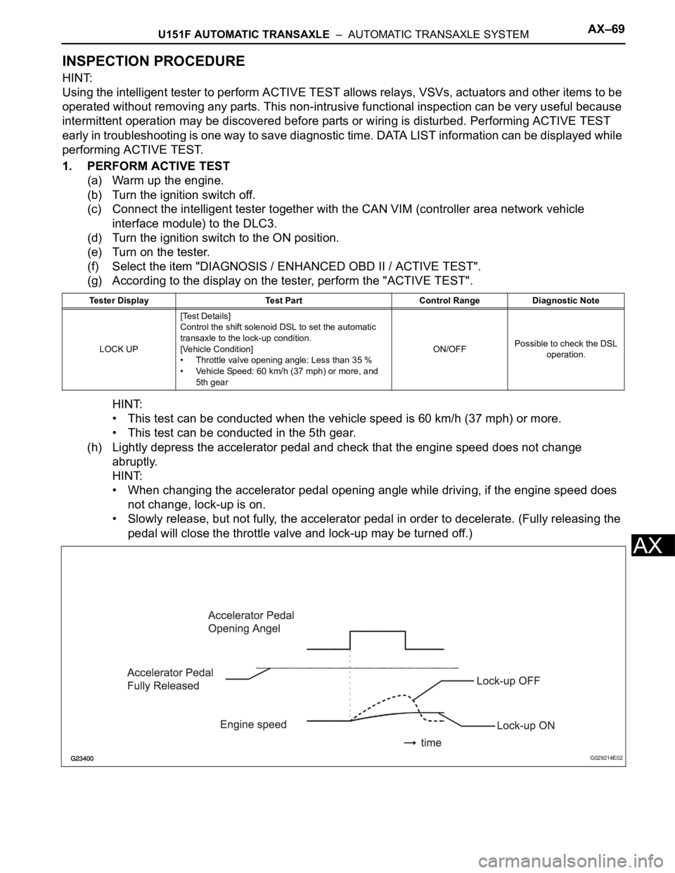
(h) Lightly depress the accelerator pedal and check that the engine speed does not change
abruptly.
HINT:
• When changing the accelerator pedal opening angle while driving, if the engine speed does
not change, lock-up is on.
• Slowly release, but not fully, the accelerator pedal in order to decelerate. (Fully releasing the
pedal will close the throttle valve and lock-up may be turned off.)
Tester Display Test Part Control Range Diagnostic Note
LOCK UP[Test Details]
Control the shift solenoid DSL to set the automatic
transaxle to the lock-up condition.
[Vehicle Condition]
• Throttle valve opening angle: Less than 35 %
• Vehicle Speed: 60 km/h (37 mph) or more, and
5th gearON/OFFPossible to check the DSL
operation.
G029214E02