2007 TOYOTA SIENNA change time
[x] Cancel search: change timePage 656 of 3000
2GR-FE ENGINE CONTROL SYSTEM – SFI SYSTEMES–363
ES
HINT:
• Although the DTC titles say oxygen sensor, these DTCs relate to the Air-Fuel Ratio (A/F) sensor.
• Sensor 1 refers to the sensor mounted in front of the Three-Way Catalytic Converter (TWC) and
located near the engine assembly.
DESCRIPTION
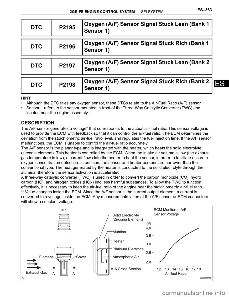
The A/F sensor generates a voltage* that corresponds to the actual air-fuel ratio. This sensor voltage is
used to provide the ECM with feedback so that it can control the air-fuel ratio. The ECM determines the
deviation from the stoichiometric air-fuel ratio level, and regulates the fuel injection time. If the A/F sensor
malfunctions, the ECM is unable to control the air-fuel ratio accurately.
The A/F sensor is the planar type and is integrated with the heater, which heats the solid electrolyte
(zirconia element). This heater is controlled by the ECM. When the intake air volume is low (the exhaust
gas temperature is low), a current flows into the heater to heat the sensor, in order to facilitate accurate
oxygen concentration detection. In addition, the sensor and heater portions are narrower than the
conventional type. The heat generated by the heater is conducted to the solid electrolyte through the
alumina, therefore the sensor activation is accelerated.
A three-way catalytic converter (TWC) is used in order to convert the carbon monoxide (CO), hydro
carbon (HC), and nitrogen oxides (HOx) into less harmful substances. To allow the TWC to function
effectively, it is necessary to keep the air-fuel ratio of the engine near the stoichiometric air-fuel ratio.
*: Value changes inside the ECM. Since the A/F sensor is the current output element, a current is
converted to a voltage inside the ECM. Any measurements taken at the A/F sensor or ECM connectors
will show a constant voltage.
DTC P2195Oxyg en ( A/ F) S en so r S ig n al Stu ck Lea n (Ban k 1
Sensor 1)
DTC P2196Oxygen (A/F) Sensor Signal Stuck Rich (Bank 1
Sensor 1)
DTC P2197Oxyg en ( A/ F) S en so r S ig n al Stu ck Lea n (Ban k 2
Sensor 1)
DTC P2198Oxygen (A/F) Sensor Signal Stuck Rich (Bank 2
Sensor 1)
G038016E06
Page 662 of 3000

2GR-FE ENGINE CONTROL SYSTEM – SFI SYSTEMES–369
ES
9. Drive the vehicle at a proper vehicle speed to perform fuel-cut operation (refer to the following HINT)
(Procedure "D").
HINT:
Fuel-cut is performed when the following conditions are met:
• Accelerator pedal is fully released.
• Engine speed is 2500 rpm or more (fuel injection resumes at 1000 rpm).
10. Accelerate the vehicle to 40 mph (64 km/h) or more by depressing the accelerator pedal for at least 10
seconds (Procedure "E").
11. Soon after performing procedure "J" on the previous page, release the accelerator pedal for at least 4
seconds without depressing the brake pedal, in order to execute fuel-cut control (Procedure "F").
12. Allow the vehicle to decelerate until the vehicle speed declines to less than 6 mph (10 km/h).
13. Repeat procedures from "H" through "K" in this section at least 3 times per driving cycle.
HINT:
Completion of all A/F sensor monitors is required to change the value in TEST RESULT.
CAUTION:
Strictly observe posted speed limits, traffic laws, and road conditions when performing these
driving patterns.
INSPECTION PROCEDURE
HINT:
Malfunctioning areas can be identified by performing the A/F CONTROL function provided in the ACTIVE
TEST. The A/F CONTROL function can help to determine whether the Air-Fuel Ratio (A/F) sensor, Heated
Oxygen (HO2) sensor and other potential trouble areas are malfunctioning.
The following instructions describe how to conduct the A/F CONTROL operation using an intelligent
tester.
(a) Connect the intelligent tester to the DLC3.
(b) Start the engine and turn the tester on.
(c) Warm up the engine at an engine speed of 2500 rpm for approximately 90 seconds.
(d) Select the following menu items on the tester: DIAGNOSIS / ENHANCED OBD II / ACTIVE TEST / A/
F CONTROL.
(e) Perform the A/F CONTROL operation with the engine in an idling condition (press the RIGHT or LEFT
button to change the fuel injection volume).
(f) Monitor the voltage outputs of the A/F and HO2 sensors (AFS B1S1 and O2S B1S2 or AFS B2S1 and
O2S B2S2) displayed on the tester.
HINT:
• The A/F CONTROL operation lowers the fuel injection volume by 12.5% or increases the injection
volume by 25%.
• Each sensor reacts in accordance with increases and decreases in the fuel injection volume.
Standard voltage
NOTICE:
The Air-Fuel Ratio (A/F) sensor has an output delay of a few seconds and the Heated Oxygen
(HO2) sensor has a maximum output delay of approximately 20 seconds.
Tester Display (Sensor) Injection Volumes Status Voltages
AFS B1S1 or AFS B2S1 (A/F) +25% Rich Less than 3.0
AFS B1S1 or AFS B2S1 (A/F) -12.5% Lean More than 3.35
O2S B1S2 or O2S B2S2 (HO2) +25% Rich More than 0.55
O2S B1S2 or O2S B2S2 (HO2) -12.5% Lean Less than 0.4
Page 665 of 3000
ES–3722GR-FE ENGINE CONTROL SYSTEM – SFI SYSTEM
ES
• COMPL indicates that the component is functioning
normally.
• INCMPL indicates that the component is
malfunctioning.
(g) Select the following menu items: DIAGNOSIS /
ENHANCED OBD II / MONITOR INFO / TEST RESULT /
RANGE B1S1, then press the ENTER button.
(h) Check the test value of the A/F sensor output current
during fuel-cut.
Result
B
A
(a) Connect the intelligent tester to the DLC3.
(b) Start the engine.
(c) Turn the tester on.
(d) Warm up the Air-Fuel Ratio (A/F) sensor at an engine
speed of 2500 rpm for 90 seconds.
(e) Select the following menu items on the tester:
DIAGNOSIS / ENHANCED OBD II / SNAPSHOT /
MANUAL SNAPSHOT / USER DATA / AFS B1S1 or AFS
B2S1 and ENGINE SPD.
(f) Check the A/F sensor voltage 3 times, when the engine
is in each of the following conditions:
(1) While idling (check for at least 30 seconds) (Step
(1))
(2) At an engine speed of approximately 2500 rpm
(without any sudden changes in engine speed)
(Step (2))
(3) Raise the engine speed to 4000 rpm and then
quickly release the accelerator pedal so that the
throttle valve is fully closed (Step (3)).
Standard voltage
HINT:
For more information, see the diagrams below.
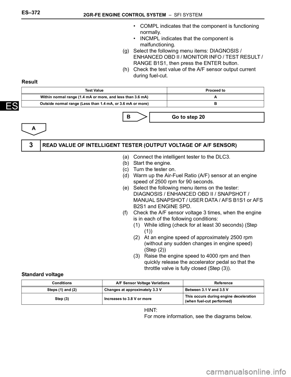
Test Value Proceed to
Within normal range (1.4 mA or more, and less than 3.6 mA) A
Outside normal range (Less than 1.4 mA, or 3.6 mA or more) B
Go to step 20
3READ VALUE OF INTELLIGENT TESTER (OUTPUT VOLTAGE OF A/F SENSOR)
Conditions A/F Sensor Voltage Variations Reference
Steps (1) and (2) Changes at approximately 3.3 V Between 3.1 V and 3.5 V
Step (3) Increases to 3.8 V or moreThis occurs during engine deceleration
(when fuel-cut performed)
Page 675 of 3000
ES–3822GR-FE ENGINE CONTROL SYSTEM – SFI SYSTEM
ES
Others:
TYPICAL MALFUNCTION THRESHOLDS
P2238 and P2241 (Open circuit between AF+ and AF-):
P2238 and P2241 (Short circuit between AF+ and GND):
P2238 and P2241 (Short circuit between AF+ and AF-):
P2239 and P2242 (Short circuit between AF+ and +B):
P2252 and P2255 (Short circuit between AF- and GND):
P2253 and P2256 (Short circuit between AF- and +B):
WIRING DIAGRAM
Refer to DTC P2195 (See page ES-359).
INSPECTION PROCEDURE
HINT:
For use of the intelligent tester only:
Malfunctioning areas can be identified by performing the A/F CONTROL function provided in the ACTIVE
TEST. The A/F CONTROL function can help to determine whether the Air-Fuel Ratio (A/F) sensor, Heated
Oxygen (HO2) sensor and other potential trouble areas are malfunctioning.
The following instructions describe how to conduct the A/F CONTROL operation using the intelligent
tester.
(a) Connect the intelligent tester to the DLC3.
(b) Start the engine and turn the tester on.
(c) Warm up the engine at an engine speed of 2500 rpm for approximately 90 seconds.
(d) Select the following menu items on the tester: DIAGNOSIS / ENHANCED OBD II / ACTIVE TEST / A/
F CONTROL.
(e) Perform the A/F CONTROL operation with the engine in an idling condition (press the RIGHT or LEFT
button to change the fuel injection volume).
Engine Running
Fuel-cut OFF
Time after fuel-cut OFF 5 seconds or more
A/F sensor heater ON
Battery voltage 11 V or more
Ignition switch ON
Time after ignition switch is OFF to ON 5 seconds or more
Battery voltage 11 V or more
Ignition switch ON
Time after ignition switch is OFF to ON 5 seconds or more
A/F sensor admittance Below 0.022 1/
AF+ terminal voltage 0.5 V or less
Difference between AF+ terminal and AF- terminal
voltage0.1 V or less
AF+ terminal voltage More than 4.5 V
AF- terminal voltage 0.5 V or less
AF- terminal voltage More than 4.5 V
Page 681 of 3000
ES–3882GR-FE ENGINE CONTROL SYSTEM – SFI SYSTEM
ES
DTC SUMMARY
DESCRIPTION
The circuit description can be found in the EVAP (Evaporative Emission) System (See page ES-404).
INSPECTION PROCEDURE
Refer to the EVAP System (See page ES-404).
MONITOR DESCRIPTION
5 hours*1 after the ignition switch is turned off, the electric vacuum pump creates negative pressure
(vacuum) in the EVAP (Evaporative Emission) system. The ECM monitors for leaks and actuator
malfunctions based on the EVAP pressure.
HINT:
*1: If the engine coolant temperature is not below 35
C (95F) 5 hours after the ignition switch is turned
off, the monitor check starts 2 hours later. If it is still not below 35
C (95F) 7 hours after the ignition switch
is turned off, the monitor check starts 2.5 hours later.
*2: If only a small amount of fuel is in the fuel tank, it takes longer for the EVAP pressure to stabilize.
DTC P2420Evaporative Emission System Switching Valve
Control Circuit High
DTC No. Monitoring Item DTC Detection Condition Trouble Area Detection TimingDetection
Logic
P2420Vent valve stuck
open (vent)The following condition is met
during key-off EVAP monitor
• EVAP pressure change when
vent valve is closed (ON) less
than 2.3 mmHg• Pump module (0.02 inch
orifice, vacuum pump, vent
valve)
• Connector / wire harness
(Pump module - ECM)
•ECMIgnition switch off 2 trip
Sequence Operation Description Duration
- ECM activationActivated by soak timer, 5 hours (7 or 9.5 hours) after ignition switch is
turned off.-
AAtmospheric pressure
measurementVent valve turned is OFF (vent) and EVAP system pressure is
measured by ECM in order to register atmospheric pressure.
If pressure in EVAP system is not between 70 kPa and 110 kPa (525
mmHg and 825 mmHg), ECM cancels EVAP system monitor.10 seconds
BFirst 0.02 inch leak pressure
measurementIn order to determine 0.02 inch leak pressure standard, vacuum pump
creates negative pressure (vacuum) through 0.02 inch orifice and then
ECM checks if vacuum pump and vent valve operate normally.60 seconds
CEVAP system pressure
measurementVent valve is turned ON (closed) to shut EVAP system.
Negative pressure (vacuum) is created in EVAP system, and then
EVAP system pressure is measured. Write down measured value as
they will be used in leak check.
If EVAP pressure does not stabilize within 15 minutes, ECM cancels
EVAP system monitor.15 minutes
*2
D Purge VSV monitorPurge VSV is opened and then EVAP system pressure is measured
by ECM.
Large increase indicates normal.10 seconds
ESecond 0.02 inch leak pressure
measurementAfter second 0.02 inch leak pressure measurement, leak check is
performed by comparing first and second 0.02 inch leak pressure
standards.
If stabilized system pressure is higher than second 0.02 inch leak
pressure standard, ECM determines that there is a leak in EVAP
system.60 seconds
F Final checkAtmospheric pressure is measured and then monitoring result is
recorded by ECM.-
Page 683 of 3000

ES–3902GR-FE ENGINE CONTROL SYSTEM – SFI SYSTEM
ES
MONITOR STRATEGY
TYPICAL ENABLING CONDITIONS
Key-off monitor sequence 1 to 8
1. Atmospheric pressure measurement
2. First reference pressure measurement
3. EVAP canister vent valve close stuck check
4. Vacuum introduction
5. EVAP canister purge valve close stuck check
6. Second reference pressure measurement
Related DTC P2420: Vent valve stuck open (vent)
Required Sensors/Components Purge VSV and pump module
Frequency of Operation Once per driving cycle
Duration Within 2 minutes
MIL Operation 2 driving cycles
Sequence of Operation None
The monitor will run whenever these DTCs are not
presentNone
Atmospheric pressure 70 to 110 kPa (525 to 825 mmHg)
Battery voltage 10.5 V or more
Vehicle speed Less than 2.5 mph (4 km/h)
Ignition switch OFF
Time after key-off 5 or 7 or 9.5 hours
EVAP pressure sensor malfunction (P0450, P0452,
P0453)Not detected
EVAP canister purge valve Not operated by scan tool
EVAP canister vent valve Not operated by scan tool
EVAP leak detection pump Not operated by scan tool
Both of the following conditions 1 and 2 are set before
key-off-
1. Duration that vehicle driven 5 minutes or more
2. EVAP purge operation Performed
ECT 4.4 to 35
C (40 to 95F)
IAT 4.4 to 35
C (40 to 95F)
Next sequence is run if the following condition is met -
Atmospheric pressure change Less than 0.3 kPa (2.25 mmHg) in 1 second
Next sequence is run if the following conditions are met Condition 1, 2 and 3
1. EVAP pressure just after reference pressure
measurement start-1 kPa (-7.5 mmHg) or less
2. Reference pressure -4.85 to -1.057 kPa (-36.384 to -7.929 mmHg)
3. Reference pressure Saturated within 1 minutes
Next sequence is run if the following condition is met -
EVAP pressure change after vent valve is ON 0.3 kPa (2.25 mmHg) or more
Next sequence is run if the following condition is met -
EVAP pressure Saturated within 15 minutes
Next sequence is run if the following condition is met -
EVAP pressure change after purge valve is open 0.3 kPa (2.25 mmHg) or more
Next sequence is run if the following conditions are met Condition 1, 2, 3 and 4
Page 704 of 3000
ES–4182GR-FE ENGINE CONTROL SYSTEM – SFI SYSTEM
ES
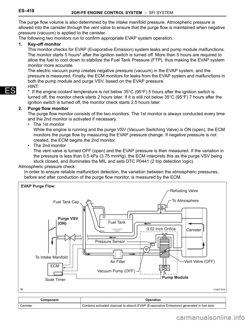
The purge flow volume is also determined by the intake manifold pressure. Atmospheric pressure is
allowed into the canister through the vent valve to ensure that the purge flow is maintained when negative
pressure (vacuum) is applied to the canister.
The following two monitors run to confirm appropriate EVAP system operation.
1. Key-off monitor
This monitor checks for EVAP (Evaporative Emission) system leaks and pump module malfunctions.
The monitor starts 5 hours* after the ignition switch is turned off. More than 5 hours are required to
allow the fuel to cool down to stabilize the Fuel Tank Pressure (FTP), thus making the EVAP system
monitor more accurate.
The electric vacuum pump creates negative pressure (vacuum) in the EVAP system, and the
pressure is measured. Finally, the ECM monitors for leaks from the EVAP system and malfunctions in
both the pump module and purge VSV, based on the EVAP pressure.
HINT:
*: If the engine coolant temperature is not below 35
C (95F) 5 hours after the ignition switch is
turned off, the monitor check starts 2 hours later. If it is still not below 35
C (95F) 7 hours after the
ignition switch is turned off, the monitor check starts 2.5 hours later.
2. Purge flow monitor
The purge flow monitor consists of the two monitors. The 1st monitor is always conducted every time
and the 2nd monitor is activated if necessary.
• The 1st monitor
While the engine is running and the purge VSV (Vacuum Switching Valve) is ON (open), the ECM
monitors the purge flow by measuring the EVAP pressure change. If negative pressure is not
created, the ECM begins the 2nd monitor.
• The 2nd monitor
The vent valve is turned OFF (open) and the EVAP pressure is then measured. If the variation in
the pressure is less than 0.5 kPa (3.75 mmHg), the ECM interprets this as the purge VSV being
stuck closed, and illuminates the MIL and sets DTC P0441 (2 trip detection logic).
Atmospheric pressure check:
In order to ensure reliable malfunction detection, the variation between the atmospheric pressures,
before and after conduction of the purge flow monitor, is measured by the ECM.
Component Operation
Canister Contains activated charcoal to absorb EVAP (Evaporative Emissions) generated in fuel tank.
A126271E05
Page 804 of 3000

ES–282GR-FE ENGINE CONTROL SYSTEM – SFI SYSTEM
ES
• Vehicle was driven in the city area (or on free-
way) for 10 minutes or more.
(b) Monitor Conditions
(1) Turn the ignition switch off and wait for 6 hours.
HINT:
Do not start the engine until checking Readiness
Monitor status. If the engine is started, the step
described above must be repeated.
(c) Monitor Status
(1) Connect an intelligent tester to the DLC3.
(2) Turn the ignition switch to the ON position.
(3) Turn the tester or scan tool ON.
(4) Check the Readiness Monitor status displayed
on the tester or scan tool.
If the status does not switch to COMPL
(complete), restart the engine, make sure that
the preconditions have been met, and then
perform the Monitor Conditions again.
4. A/F SENSOR AND HO2S MONITORS
(a) Preconditions
The monitor will not run unless:
• 2 minutes or more have elapsed since the engine
was started.
• The Engine Coolant Temperature (ECT) is 75
C
(167
F) or more.
• Cumulative driving time at a vehicle speed of 30
mph (48 km/h) or more exceeds 6 minutes.
• Air-fuel ratio feedback control is performed.
• Fuel-cut control is performed for 8 seconds or
more (for the Rear HO2 Sensor Monitor).
(b) Drive Pattern for front A/F sensor and HO2 sensor.
(1) Connect an intelligent tester to the DLC3.
(2) Turn the ignition switch to the ON position.
(3) Turn the tester ON.
(4) Clear the DTCs.
(5) Start the engine, and warm it up until the ECT
reaches 75
C (167F) or higher.
(6) Drive the vehicle at 38 mph (60 km/h) or more
for at least 10 minutes.
(7) Change the transmission to the 2nd gear.
(8) Accelerate the vehicle to 40 mph (64 km/h) or
more by depressing the accelerator pedal for at
least 10 seconds (Procedure "A").
(9) Soon after performing procedure "A" above,
release the accelerator pedal for at least 4
seconds without depressing the brake pedal, in
order to execute fuel-cut control (Procedure "B").
(10) Allow the vehicle to decelerate until the vehicle
speed declines to less than 6 mph (10 km/h)
(Procedure "C").
(11) Repeat procedures from "A" through "C" above
at least 3 times in one driving cycle.